Table of Contents
Advertisement
Advertisement
Table of Contents

Subscribe to Our Youtube Channel
Summary of Contents for Brite View BVH-H5101C
- Page 3 Preface BVH-5101 is a wireless AP device with PowerLine Communication (PLC) capability. With the latest 500Mbps PLC technology (Homeplug AV), crossing-floor communication in a concrete building, which has been a big problem for wireless networking, is made as a extreme reliable product. Its cutting edge 802.11n wireless technology provides the highest wireless throughput for devices in the same floor.
- Page 4 Important Safety Notes BVH-5101 is intended for connection to the AC power line. For installation instructions, refer to the Installation section. The following precautions should be taken when using this product. Please read all instructions before installing and operating this product. Please keep all instructions for later reference.
-
Page 5: Table Of Contents
TABLET of CONTENT CH 1. PRODUCT OVERVIEW....................6 Package Content ............................... 6 Buttons and LEDs ............................. 6 CH 2. HARDWARE INSTALLATION ...................9 Application 1 – Link to remote DSL via Powerline ..................9 Application 2 – Wireless AP + Ethernet Switch ................... 10 Application 3–... - Page 6 Upgrade Firmware ------------------------------------------------------------------------------------------------------------- 29 Settings Management -------------------------------------------------------------------------------------------------------- 30 Status ------------------------------------------------------------------------------------------------------------------------------ 30 Statistics -------------------------------------------------------------------------------------------------------------------------- 31 System Log ---------------------------------------------------------------------------------------------------------------------- 32 Reboot................................32 Reboot System------------------------------------------------------------------------------------------------------------------ 32 Channel Number ............................. 32 *FEDERAL COMMUNICATIONS COMMISSION INTERFERENCE STATEMENT......... 33 CH 4 ENHANCE PLC PERFORMANCE DURING INSTALLATION ........35 AC Outlets Connection...........................
-
Page 7: Ch 1. Product Overview
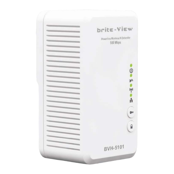
Ch 1. Product Overview Package Content Before starting the installation of the device, please make sure the package contains the following items: Single pack Combo pack Device Powerline Ethernet Powerline Wireless Powerline Wireless Bridge N Extender N Extender RJ-45 Cable x 1 RJ-45 Cable x2 Accessories Buttons and LEDs 500 Mbps Powerline Wireless N Extender (BVH-5101) - Page 8 500 Mbps Powerline Bridge (BVP-5100) LEDs ON: Power on and ready. Power LED BLINKING: During group pairing procedure (creating an encrypted PLC network). In this procedure, the device is creating or being joined into Green same logical network and will continue 2 minutes blinking, until the procedures succeed or canceled.
- Page 9 Ethernet Link / Act ON: Ethernet Link Detected. BLINKING: Ethernet traffic detected. OFF: No Ethernet Link detected. Buttons WPS Button Press it to enable PBC (Press Button Configuration) for WPS authentication. When WPS function is started, the WLAN Link / Act LED will be blinking. Group Button Press 1 to 3 seconds ( until the Power LED blinking ) and release button: this will enter group pairing procedure(creating an encrypted PLC network).
-
Page 10: Ch 2. Hardware Installation
Ch 2. Hardware Installation Once you check everything from the package, you can start to deploy the PLC devices. To connect this AP wirelessly need to search and connect the SSID (Wi-Fi name) of this device: BVH-5101_XXXXXX (factory default is no wireless security setting) Please see the following application diagrams for different application connections of this device. -
Page 11: Application 2 - Wireless Ap + Ethernet Switch
Application 2 – Wireless AP The Powerline Wireless N Extender can be a central 802.11n access point to for all WLAN devices to connect. Application 3 – Multiple Floor Home Networking (1) When Wi-Fi signal is not good for devices in different rooms to access, use Powerline technology powered by the Powerline Wireless N Extender to extend home networking range to other rooms. -
Page 12: Application 3- Multiple Floor Home Networking
Application 3 – Multiple Floor Home Networking (2) By turning off the Wi-Fi function (need to operate in the web page settings), HomePlug AV Wireless N Extender acts as Powerline Ethernet Bridge, which, when used together with other remote Powerline Ethernet Bridge, enables other remote Ethernet devices (ex. IP devices or PC) on the different floor to communicate via the embedded Powerline technology. - Page 13 Create Private Encrypted PLC Network Group (group pairing procedure) The Powerline bridges are compliant HomePlug AV specification. Every ‘HomePlug AV’ compliant PLC device has the same default network name, “HomePlug AV”, which is capable of communicating with other “HomePlug AV” compliant devices. This is so called the “public network”. Two or more powerline devices under the same network can communicate with one another.
- Page 14 Remove Device From a Network Group If you would like to remove device from a network group, you can generate a new group name for the device that you would like to remove by following the Step I. This makes the device not able to communicate with the original network group.
-
Page 15: Ch 3. Advanced Wi-Fi Setting - Via Web Browser
Ch 3. Advanced Wi-Fi Setting – via Web Browser Before Starting Configure The configuration of this device is through web-browser on a PC. The default IP address of the device is 192.168.2.253, and the subnet-mask is 255.255.255.0. The DHCP server inside the device is default to “Off”... -
Page 16: Home
Home Select Language The device provides 3 languages, English, Tradition Chinese and Simple Chinese for you to select one you want to use. Setup Wizard The setup Wizard can help you to finish settings in minutes. Open the page from the left panel and click “Next”... -
Page 17: Operation Mode Configuration
Step 5:Click “Finish” button and the device will reboot to apply the settings. Operation Mode Configuration This device supports five operation modes for the IP network. Click to select one between the following wireless operation modes, then click Apply button. AP Mode This device act as Wireless Access Point (AP) for wireless clients and provides a connection to Ethernet and PLC. - Page 18 WDS (Root AP) The wireless radio of device serves for the other AP and provides a connection to a wired LAN (the other AP must use the same chipset with this device) WDS + AP Mode This mode combines WDS plus AP modes, and it not only allows WDS connections but also the wireless clients can survey and associate to the device...
- Page 19 WDS Mode The WDS system is used to create a network of AP’s that can be used as a single “virtual” AP. The device forwards the packets to another AP with WDS function. When this mode is selected, all the wireless clients can’t survey and connect to the device.
-
Page 20: Internet Settings
Internet Settings LAN (Local Area Network Settings) LAN setup Item Description IP Address The Internet Protocol (IP) address. Subnet mask The number used to identify the IP subnet network. Default Gateway This is the default gateway for the LAN PCs. This is the primary DNS server for the LAN PCs which automatically Primary DNS Server get DNS IP address from this device. -
Page 21: Dhcp Clients
This is the primary DNS server for the LAN PCs which automatically Primary DNS Server get DNS IP address from this device. Secondary DNS This is the second DNS server for the LAN PCs which automatically Server get DNS IP address from this device. Default Gateway This is the default gateway for the LAN PCs. -
Page 22: Wireless Settings
Wireless Settings Basic (Basic Wireless Settings) Wireless Network Item Description Radio On/Off Click to enable/disable wireless function. The available options are 11b, 11g, 11g/n HT20, 11g/n HT40 PLUS Network Mode (default), 11 g/n HT40 MINUS The SSID, which is also called ESSID is a unique identifier that Network Name wireless networking devices use in order to establish and maintain (SSID) -
Page 23: Advanced
Mode packets and legacy packets. Green Field mode: the device transmits HT packets without legacy compatible part. But the device receives and decodes both Green Field and legacy packets. The 11n device inserts the Guard Interval into the signal. You Short Guard Interval can choose the interval between “Long”... -
Page 24: Security
Beacons are the packets sending by Access point to synchronize the wireless network. The beacon interval is the Beacon Interval time interval between beacons sending by this unit in AP or AP+WDS mode. The default and recommended beacon interval is 100 milliseconds. This is the Delivery Traffic Indication Map. - Page 25 The default SSID and Wi-Fi key Wireless Security/Encryption Settings Item Description Disable, OPEN, SHARED, WEPAUTO, WPA, WPA-PSK, WPA2, Security Mode WPA2-PSK, WPA/WPA2 PSK, WPA/WPA2, 802.1X. Security Mode: Choose one as the wireless authentication among the following types: Open, Shared, WEP Auto, WPA, WPA-PSK, WPA2, WPA2-PSK, WPA/WPA2-PSK, WPA/WPA2, and 802.1 X.
- Page 26 WPA Authentication Mode This device supports six WPA modes including WPA-PSK (Pre-Shared Key), WPA, WPA2-PSK, WPA2 and additional WPA/WPA2 PSK and WPA/WPA2 mixed mode. For individual and residential user, it is recommended to select WPA-PSK or WPA2-PSK to encrypt the link without additional RADIUS server. This mode requires only an access point and client station that supports WPA-PSK.
-
Page 27: Wps
WPS (Wi-Fi Protected Setup) This function helps to establish the Wi-Fi security. For AP mode, it can be setup one WPS method including PIN (Personal Identification Number) and PBC (Push Button Certification). To begin the WPS progress, the WLAN security must be setup first. Please setup one among WPAPSK, WPA2PSK, WPA/WPA2PSK and then apply WPS setting. -
Page 28: Site Survey
Site Survey (AP Mode Site Survey) Site survey shows information of APs nearby; you may choose one of these APs connecting. MAC Filter MAC filtering allows the user to either limit specific MAC addresses from associating with the AP, or specifically indicates which MAC addresses can associate with the AP. -
Page 29: Administration
Administration Management (System Management) -
Page 30: Upgrade Firmware
Administrator Settings Item Description Account Enter the name for login. The default name is “root”. Password Enter the password for login. The default password is “root”. NTP Settings Item Description Sync with host Synchronizing current time with your PC Time Zone Select local time zone. -
Page 31: Settings Management
Settings Management You might save system settings by exporting them to a configuration file, restore them by importing the file, or reset them to factory default. Status The page shows system status information. -
Page 32: Statistics
Statistics Administrator Settings Item Description Memory total This is the total memory size for this device. Memory left The available memory size shows in this field. All interfaces The information likes “Rx Packet”, “Rx Byte”, “Tx Packet” and “Tx Byte” shows the status of all interface including “Ethernet and Wireless”. -
Page 33: Reboot
Reboot Reboot System Channel Number The following table is the available frequencies (in MHz) for the 2.4 GHz radio: Channel No. Frequency Region Domain 2412 Americas, Taiwan, EMEA, Japan, Australia and China 2417 Americas, Taiwan, EMEA, Japan, Australia and China 2422 Americas, Taiwan, EMEA, Japan, Australia and China 2427... -
Page 34: Federal Communications Commission Interference Statement
2462 Americas, Taiwan, EMEA, Japan, Australia and China 2467 EMEA, Japan, Australia and China 2472 EMEA, Japan, Australia and China 2484 Japan, only in 802.11b mode *: EMEA (Europe, the Middle East and Africa). The available channel is set by the factory according to the region of distribution and can’t be changed by user. - Page 35 Canada, Industry Canada (IC) Notices This Class B digital apparatus complies with Canadian ICES-003 and RSS-210. Operation is subject to the following two conditions: (1) this device may not cause interference, and (2) this device must accept any interference, including interference that may cause undesired operation of the device.
-
Page 36: Ch 4 Enhance Plc Performance During Installation
Ch 4 Enhance PLC Performance During Installation This Powerline device sends data to remote device using WLAN or PLC technology. When it sends data to another remote Powerline device over the existing electrical wiring in your home, it may be affected by noises on the electric wire or the length of the wiring between transmitting and receiving devices. -
Page 37: Connection Via Power Strip
Connection via Power Strip If you must connect this device to a power strip, please keep the following recommendation in mind: • Make sure the power strip does not have a noise filter or a surge protector, as these features may impair communication signaling of the Powerline device sent over the electric wiring, and its throughput or distance will be degraded. -
Page 38: Ch 5 Specifications
Ch 5 Specifications Powerline Wireless N Extender Standards WLAN: IEEE 802.11 b/g, IEEE 802.11n LAN: IEEE 802.3, IEEE 802.3u Powerline: HomePlug AV 1.0 Maximum Throughput WLAN to Ethernet: up to 93 Mbps (Under 802.11n 40MHz) Powerline to Ethernet: TCP: 92 Mbps Frequency band WLAN: 2.4~2.4835GHz PLC: 2~ 68MHz... - Page 39 Power consumption (Note: Ethernet and Wi‐Fi is connected and running) LEDs POWER LED (Green); PLC Link/Activity LED (Green); Wireless & Security LED (dual color); Ethernet (Green) Buttons GROUP/Pairing Power on/off RESET PLC PHY Rate 500 Mbps OFDM (QAM 8/16/64/256/1024/4096, BPSK, QPSK, ROBO) PLC Modulation PLC Distance AC Wire : up to 300 meters...
- Page 40 ...
Need help?
Do you have a question about the BVH-H5101C and is the answer not in the manual?
Questions and answers