Table of Contents
Advertisement
Advertisement
Table of Contents

Subscribe to Our Youtube Channel
Summary of Contents for Carmanah A704-5
- Page 1 Owner’s Manual Model A704-5 Wireless Aviation Lighting System...
-
Page 2: Table Of Contents
Owner’s Manual | Model A704-5 Aviation Lighting System Contents Introduction ............................4 Precautions............................5 Viewing Precautions ........................5 Battery Precautions ........................5 Electrostatic Discharge (ESD) Precautions..................6 Storage Precautions ........................6 Wireless Precautions........................6 Other Precautions........................... 6 Component Identification........................ 7 Model A704-5 Light......................... - Page 3 Model A704-5 AC/DC Charger (Part# 48898)................38 10.0 Service and Warranty........................39 11.0 FCC Compliance..........................40 11.1 Introduction ........................... 40 11.2 FCC Statement for Model A704-5 Light and Wireless Controller..........40 11.3 FCC Statement for Non-wireless Model A704-5 Light ..............40 Appendix A: Glossary......................... 41 Appendix B: Model A704-5 Battery Replacement................
-
Page 4: Introduction
This manual describes the increased functionality of v3.00 firmware, released October 2007. Some of the features described in this manual are not available in older systems. For your convenience, both the Model A704-5 light and wireless controller have quick start instructions that can be found in the following sections: Model A704-5 Light: section 4.2 Model A704-5 Light Quick Start Guide... -
Page 5: Precautions
) as the maximum exposure limit for viewing for up to 16 minutes. This power density can be produced by a Model A704-5 at the lens surface when actively emitting infrared light. High-power visible-spectrum LEDs also pose an eye safety risk if viewed inappropriately. -
Page 6: Electrostatic Discharge (Esd) Precautions
Misaligned connector pins can cause damage to system components at power-on. Storage Precautions When in storage, the A704-5 light will require periodic recharging to maximize the life expectancy of its batteries. The interval between recharging is dependent upon the temperature where the light is stored. -
Page 7: Component Identification
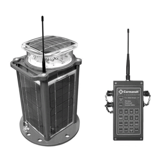
Owner’s Manual | Model A704-5 Aviation Lighting System Component Identification Model A704-5 Light Top solar panel Optional antenna Reflector Push button Lens Indicator LEDs Main beam LEDs Handle Antenna connector Side solar panels External power connector Base plate with mounting holes Figure 3-1: Model A704-5 Light Component Identification ©... -
Page 8: Wireless Controller
Owner’s Manual | Model A704-5 Aviation Lighting System Wireless Controller Antenna ARCAL Communications connector connector External power Vent connector Figure 3-2: Wireless Controller Component Identification © 2008 Carmanah Technologies Corporation Last revised: April 2008... -
Page 9: Model A704-5 Aviation Light Operation
Each output mode can be selected by pressing a push button on the light itself or by using the optional wireless controller. If the light needs to be extinguished immediately, a single press of the push button places the light into Standby Mode. When in Standby Mode the Model A704-5 will not illuminate until the next nightfall. -
Page 10: Programming Options
Programming Options There are two options for programming the Model A704-5 light: Push Button: The black push button on the top of the Model A704-5 allows manual programming of the Model A704-5 features and operation. Wireless Controller: The wireless controller is capable of performing all push button operations as well as several advanced operations. -
Page 11: Push Button Operation
Table 4-1: Overview of Command Levels and Modes illustrates the order of commands and modes for programming the Model A704-5. This table is followed by a description of the light’s operation in each mode. Read this table from left to right. - Page 12 Button Sequence [0, 1]: Standby Mode Button sequence [0, 1] puts the Model A704-5 in Standby Mode. This will immediately extinguish the light, and the light will resume autonomous operation at its last set Autonomous Output Mode after detecting a day-to-night transition.
- Page 13 – such as poor visibility due to bad weather conditions. To activate a high-intensity output mode, use [1, 1] for low, [1, 2] for medium, and [1, 3] for high. Day or night, the Model A704-5 will immediately turn on at the selected temporary high-intensity setting, and will remain on for one hour.
- Page 14 Ship Mode, hold the button until the amber LED flashes twice, then release. Immediately press the button once to put the Model A704-5 into Ship Mode. When in Ship Mode, the Model A704-5 will remain off until the push button is pressed. A day-to-night transition will not activate the Model A704-5 when in this mode.
- Page 15 Button Sequence [4, 2]: UCS Status To determine if the UCS is enabled or disabled on the A704-5, use button sequence [4, 2] to request the UCS status. The indicator LEDs will blink 3 times to show the UCS status as follows:...
-
Page 16: Automatic Light Control (Alc)
4.3.4 24-Hour Shutoff If the Model A704-5 senses ambient light levels of 30 lux or less for 24 consecutive hours, it will assume it is being stored and automatically enter Ship Mode to preserve the battery. The ambient light thresholds are set so that a very dark winter season will not cause the Model A704-5 to enter Ship Mode unintentionally. -
Page 17: Wireless Controller Operation
Owner’s Manual | Model A704-5 Aviation Lighting System Wireless Controller Operation Keep the controller at a distance of at least 3 feet (1 meter) from the light. Proper Antenna Orientation The effective range of the transmitter is 2.5 miles (4 km) for the 1 watt controller and ~1.2 miles (~2 km) for the ½... - Page 18 Owner’s Manual | Model A704-5 Aviation Lighting System Understanding the Controller The A704-5 wireless controller is made of rugged aluminum with a sealed backlit keypad and a 900 MHz transceiver. The wireless controller enables secure configuration and operation of the A704-5 light and is designed to withstand water immersion.
-
Page 19: Wireless Controller Quick Start Guide
Administrator Mode 5.4.1 User Mode User Mode allows an operator to control one or more A704-5 lights with the operations listed in sections 5.6 Basic User Operations and 5.7 Advanced User Operations. In User Mode, the wireless controller turns off after 60 minutes of inactivity to avoid unauthorized access and to maximize battery life. -
Page 20: Administrator Mode
Owner’s Manual | Model A704-5 Aviation Lighting System 5.4.2 Administrator Mode Administrator Mode allows an operator access to the following management operations of the wireless controller. Personal Identification Number (PIN) Management Unique Code Sequence (UCS) Management ARCAL Entry In Administrator Mode, the wireless controller turns off after 10 minutes of inactivity to avoid unauthorized access to management operations. -
Page 21: Entering The Pin
Press the AUTO button Press intensity level LOW, MED, or HIGH Press ENTER A704-5 lights in AUTO Mode located near other lights (within 1 foot) may turn off due to the light emitted from them. 5.6.4 Temporary Operation Mode Lights set to temporary high-intensity operation using the controller will remain at this intensity for 15 minutes before returning to their previously set Autonomous Mode. -
Page 22: Visible Vs. Infrared (Ir) Mode
To turn off lights: Press LIGHTS OFF Press ENTER Lights in Standby Mode do not accept the Lights Off command; the A704-5 light must be on to accept the Lights Off command. 5.6.9 Emergency Mode Emergency Mode sets all lights in all groups to emergency flash. After 15 minutes the lights will revert back to their previous autonomous state. -
Page 23: Clear
The Radio Health Diagnose function sends a command to the lights to display a radio health indication. The A704-5 light continually monitors the health of its radio module and automatically restarts the radio if needed. A count is kept of these restart events; intermittent radio problems are thus automatically recovered from and are very likely to go unnoticed in normal operation. -
Page 24: Group Control
Owner’s Manual | Model A704-5 Aviation Lighting System Lights with radios that have needed one or more automatic restarts will identify themselves to the remote operator by responding with five flashes: To send the Radio Health Diagnose (Clear) command to the lights:... -
Page 25: Keypad Backlighting
Owner’s Manual | Model A704-5 Aviation Lighting System When you finish configuring groups, exit Configure Mode on the controller: Press CONFIG (The CONFIG LED starts flashing) Press ENTER (The CONFIG LED turns off) 5.7.5 Keypad Backlighting The keypad backlighting and LED brightness can be adjusted for optimal visibility in different amounts of ambient light. -
Page 26: Pin Reset
Owner’s Manual | Model A704-5 Aviation Lighting System Re-enter the new PIN a second time to confirm The Active Group LEDs will turn off as the PIN is entered Press ENTER If both PINs match then the Enter key LED will briefly flash green... - Page 27 Owner’s Manual | Model A704-5 Aviation Lighting System Removal Reception This section details how to perform each operation. For detailed instructions on configuring an airfield for UCS see section 5.9 UCS Configuration. Generate UCS Operation: Place the controller into Administrator Mode...
-
Page 28: Ucs Configuration
UCS be transmitted to a backup controller. Initialization Both the wireless controller and A704-5 light arrive from the factory with UCS removed. Complete the following steps to initialize an airfield with a UCS: 1. If not already in Administrator Mode, put the controller into Administrator Mode; see section 5.4.2 Administrator Mode. - Page 29 4. Transmit the UCS by pressing the ENTER button on the wireless controller, see section 5.8.3 Unique Code Sequence (UCS) Management. The A704-5 light(s) will flash for five seconds to indicate that it received and accepted the new UCS. 5. When all lights have been re-keyed press the CLEAR button on the wireless controller to exit Transmit UCS Mode.
-
Page 30: Arcal Mode
Owner’s Manual | Model A704-5 Aviation Lighting System 6. When the UCS has been removed from all lights, press the CLEAR button on the wireless controller to exit Transmit UCS Mode. If some lights do not receive broadcasted UCS, they can be programmed individually by following the instructions within the section Adding a Light to a UCS System, above. -
Page 31: Factory Reset Code
Owner’s Manual | Model A704-5 Aviation Lighting System 5.11 Factory reset code Factory reset returns the controller to the factory default settings. All passwords are reset and the UCS information (if enabled) is removed. The UCS light returns to its default state, which is UCS disabled. -
Page 32: Troubleshooting
Owner’s Manual | Model A704-5 Aviation Lighting System Troubleshooting Table 6-1: Troubleshooting Symptom Hypothesis Verification Solution The light is The light is in Infrared Mode The status LEDs will all be off Toggle Infrared Mode off unresponsive to (after 10 seconds of button... -
Page 33: Critical Low Battery Recovery Method
A critical low battery condition occurs when the A704-5 batteries have been discharged to a point where the A704-5 cannot resume normal operation and battery damage is likely. In this state, the light will briefly flash about every 10 seconds, and the red and green indicator LEDs will light up during the cycle. Battery replacement is recommended, although some batteries will respond to the following advanced recharge method. - Page 34 A704-5. You can then top up the battery using the A704-5 external charging adapter. (When using the external charger, a full charge should be attained after only a few hours.) For best results you should only begin using the A704-5 after it has been fully charged. © 2008 Carmanah Technologies Corporation...
-
Page 35: Installing The Model A704-5 Aviation Light
Optional Airport Mounting Stake The Model A704-5 Aviation light can also be installed using an optional airport mounting stake. Made of galvanized steel, the airport mounting stake is suitable for permanent installation in earth and gravel. The 30"... -
Page 36: Model A704-5 Operational Maintenance/Diagnostics
Owner’s Manual | Model A704-5 Aviation Lighting System Model A704-5 Operational Maintenance/Diagnostics This section describes the procedure for performing routine maintenance checks on the Model A704-5 runway lighting system. Routine maintenance checks will ensure the system is operational and ready in the event of an emergency. -
Page 37: Maintenance And Product Care
Do not place your Model A704-5 closer to the light source than recommended in Table 9-2: Charging Alternatives, as it may overheat, or damage to one or more of the solar panels could occur. -
Page 38: Model A704-5 Ac/Dc Charger (Part# 48898)
Owner’s Manual | Model A704-5 Aviation Lighting System Model A704-5 AC/DC Charger (Part# 48898) The A704-5 AC/DC charger consists of an AC adapter with a cable that plugs into the A704-5, and a power cord that connects the AC adapter to a North-American wall outlet. -
Page 39: Service And Warranty
Before contacting Carmanah’s customer service department, please have the serial number of your A704-5 available, a brief description of the problem, as well as all details of the installation and recharging efforts. -
Page 40: Fcc Compliance
(1) This device may not cause harmful interference, and (2) this device must accept any interference received, including interference that may cause undesired operation. Changes or modifications not expressly approved by Carmanah Technologies Corporation could void your authority to operate the equipment. -
Page 41: Appendix A: Glossary
The chemistry of the batteries creates a small electrical current within them, and the electronics of the A704-5 will draw an even smaller amount of electricity to keep itself ready for use. The self- discharge is extremely low compared to the electrical currents when the A704-5 is in operation, but over time it becomes significant enough to require the regular check and recharge intervals outlined in Table 9-1: Recharge Intervals. -
Page 42: Appendix B: Model A704-5 Battery Replacement
Owner’s Manual | Model A704-5 Aviation Lighting System Appendix B: Model A704-5 Battery Replacement The following instructions describe the proper method for replacing the Model A704-5 batteries. For the safety of personnel performing the replacement, ensure all the steps are properly followed. - Page 43 Owner’s Manual | Model A704-5 Aviation Lighting System 3. Lift the head off – the head gasket seal may be sticky; see Figure 11-2. Figure 11-2: Lifting off the Head 4. Disconnect the main wiring harness from the underside of the head; see Figure 11-3.
- Page 44 Owner’s Manual | Model A704-5 Aviation Lighting System 6. Remove the ground strap from the head using the Phillips screwdriver; see Figure 11-4. Do not drop the ground strap retaining screw into the housing. Figure 11-4: Removing the Ground Strap 7.
- Page 45 Owner’s Manual | Model A704-5 Aviation Lighting System 9. Remove the battery retention bolt using the ratchet and socket with extension; see Figure 11-6. Do not contact the battery terminals with the ratchet tool. Bridging the battery terminals will create large electrical currents and could cause severe burns. Once the bolt is loosened completely, carefully remove the bolt and ground strap.
- Page 46 Owner’s Manual | Model A704-5 Aviation Lighting System 11. Pull the batteries apart and carefully remove the battery top plate; see Figure 11-8. Figure 11-8: Removing the Battery Top Plate 12. Obtain replacement battery pack and carefully insert the battery top plate 13.
- Page 47 Owner’s Manual | Model A704-5 Aviation Lighting System 17. Replace the head gasket by removing and discarding the old gasket, then inserting the new gasket. Ensure the new gasket is fully seated in the gasket groove; see Figure 11-10. Figure 11-10: Replacing the New Gasket 18.
- Page 48 Owner’s Manual | Model A704-5 Aviation Lighting System 20. While holding the head, reconnect the main harness. The proper alignment is critical. Align the white markings on the connector and the connector receptacle that indicate proper orientation. Gently push the connector on until it clicks into place.
-
Page 49: Appendix C: Power Cycling The Controller
Owner’s Manual | Model A704-5 Aviation Lighting System Appendix C: Power Cycling the Controller If your controller is unresponsive, and the LEDs unlit, and the steps outlined in the troubleshooting guide didn’t resolve the problem, perform the following steps: 1. Use an ESD wrist strap connected to a suitable electrical ground. If one is not available, avoid touching any electronics within the enclosure unless required by this process. -
Page 50: Carmanah Technologies Corporation Last Revised: April
Owner’s Manual | Model A704-5 Aviation Lighting System Figure 11-15: Battery Connector, Final Position 5. Replace the controller lid, tightening the four screws firmly. 6. Connect the AC/DC charger: the controller battery LEDs should cycle. 7. Leave the controller connected to the AC/DC charger to allow it to charge overnight. - Page 51 © 2008 Carmanah Technologies Corporation www.carmanah.com Technical Support: customerservice@carmanah.com Toll Free in Canada and the U.S.: 1.877.722.8877 International: + 250.380.0052 | Fax: + 250.380.0062 Number: A704-5_50748_Manual_vD 50748...
Need help?
Do you have a question about the A704-5 and is the answer not in the manual?
Questions and answers