Advertisement
Advertisement
Table of Contents

Summary of Contents for Peek Traffic 625X
- Page 1 625X Inductive Loop Detector Installation Guide Sarasota Series Detectors...
- Page 2 Copyright © 2008, Peek Traffic Corporation, Printed in the USA. All rights reserved. Information furnished by Peek Traffic is believed to be accurate and reliable, however Peek does not warranty the accuracy, completeness, or fitness for use of any of the information furnished. No license is granted by implication or otherwise under any intellectual property.
-
Page 3: Quick Setup
Quick Setup Verify the input voltage by looking at the label on the back of the detector (located just under the connector.) Terminate the wiring harness to the proper connector on the terminal strip for each of the desired functions (power, desired outputs, loop, etc.) Connect the harness to the detector. -
Page 4: Setup Details
Setup Details Power is supplied to the unit on pins 1 & 2 (black & white.) Ground the unit by taking pin 4 (green) to the Operator ground. The most common hook-up is for using the Pres- ence relay, pins 5 & 6 (yellow & blue.) The Pres- ence relay common, pin 5 (yellow), is taken to the common of the terminal strip on the Operator. -
Page 5: 625X Pin Connections
625X Pin Connections Function Wire Color 120VAC or 24VAC Black AC Neutral Common White Relay 2 N.O. (Normally Open) Orange Chassis Ground Green Presence Relay Common Yellow Presence Relay (Normally Open) Blue Loop Gray Loop Brown Relay 2 Common Presence Relay (Normally Closed) -
Page 6: Loop Installation Tips
Loop Installation Tips The loop consists of a 12 to 18 gauge stranded wire suitable for direct burial with low AC and DC resis- tance. The size of your loop will be determined by the width of the area in which you need detection, and the height of the vehicles you need to detect. -
Page 7: Testing The Loop
Testing the Loop A good loop is critical for reliable operation from your detector. When installing your loop, take great care not to damage the insulation of the wire. Breaks in the insulation can cause the wire to act as a wick — pull- ing in moisture, corroding the wire itself, and causing erratic operation from the detector. - Page 8 4 Foot Loop Width Loop Size Inductance(µH)* (ft) 1 Turn 2 Turns 3 Turns 4 Turns 4 × 4 4 × 6 4 × 10 4 × 15 4 × 20 4 × 25 4 × 30 4 × 35 4 ×...
- Page 9 6 Foot Loop Width Loop Size Inductance(µH)* (ft) 1 Turn 2 Turns 3 Turns 4 Turns 6 × 4 6 × 6 6 × 10 6 × 15 6 × 20 6 × 25 6 × 30 6 × 35 6 ×...
-
Page 10: Output Configuration Options
Presence means the relay will be energized the entire time a metal mass is within the field generated by the loop. The 625X has the ability to provide two presence outputs. Relay 2 can be set for presence or pulse. - Page 11 Presence—Constant presence (detect) while metal is over the loop Pulse on Entry—Momentary pulse when metal enters the loop Pulse on Exit—Momentary pulse when metal leaves the loop...
- Page 12 Sensitivity Six sensitivity settings are available using the 3-position front panel slide switch and DIP switch 1 on the back panel. (Refer to the diagram on the previous page.) SW1 = OFF (to the number side) SW1 = ON (to the ON side) At the above switch settings, the front panel slide switch posi- tions yield the following sensitivities: SW1 = OFF...
-
Page 13: Troubleshooting
Troubleshooting Q: The detector LED blinks, and it won’t detect anything. A: A blinking LED indicates there is a problem tuning the loop. An open loop, shorted loop, bad connection to the harness, loop wires twisted around the entire loop and not just the lead- in, or not enough turns in the loop are possible causes. - Page 14 625X Specifications Dimensions 3”H × 1½”W × 3½”L, excluding connector (76 mm × 38 mm × 89 mm) Supply Power 120VAC, 24VAC, 12VDC, or 24VDC Preset on order and delivery Temperature Range -40°C to +85°C (-40°F to +185°F) Outputs Presence and Relay 2 are changeover relay contacts rated at 250VAC, 5A, 150W/600VA max.
- Page 15 (See next item.) Loop Fault Indications If the 625X detects a loop fault, for example an open loop, a shorted loop, or a change in the loop’s inductance of more than 25%, then the Presence LED will flash quickly (16 times each second.) If the fault condition corrects itself, the Pres-...
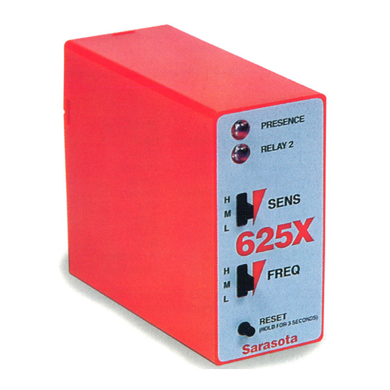
- Page 16 About the 625X • Small size: 3”H × 1½”W × 3½”L (76 × 38 × 89 mm) • Failsafe or Failsecure outputs • Increased sensitivity • Six selectable sensitivities • Easy to use controls • Second relay output mode is selectable ⎯...
Need help?
Do you have a question about the 625X and is the answer not in the manual?
Questions and answers