Advertisement
Quick Links
Advertisement

Related Manuals for WIT-COLOR ULTRA 9600

Summary of Contents for WIT-COLOR ULTRA 9600
- Page 1 ULTRA 9600 EPSON DX9...
- Page 2 Without authorization, this manual shall not be reprinted or propagated. Ultra 9600 series printer has passed 3Q Conformity of Quality Management System Certification and ISO9001 Quality Certification. Ultra 9600 series printer is up to the standard of printing equipment. Please pay attention to the following working environment when you use the printer.
- Page 3 WIT-COLOR also provide out-of-warranty printer maintenance according to the agreement. ubject to change without prior notice. Specification is s The involved description, color and model of printer only takes the reference. The exact configurations of equipment are subject to the real product.
-
Page 4: Technical Features
Gray Scale Variable Ink Drop Technology. Ultra 9600 printers adopt Gray Scale controlling system which can generate 3 kinds of drop volume with the minimum drop volume of 3.5pl. Thus the printing effect could be more precise and vivid. - Page 5 system, each picture could be dried before collected. Automatic media feeding and collecting system The automatic media feeding system is designed with photoelectric control. The system could bear large media like fabric and keep media moving in parallel. With passive media collecting system, the printer achieves low energy consumption when bearing the light media.
- Page 6 Symbols: Please pay attention to the following symbols in the course of reading Incorrect operation, which will result in serious problems. Please read carefully to avoid incorrect operation. Warning operation, which will damage printer. Please follow the instructions carefully. Hinting operation, which points out some details.
- Page 7 Chapter One Wooden Package Dimension: Length*Width*Height: 2.82*0.82*0.80m Printer Dimension: Length*Width*Height: 2.70*0.72*1.30m There must be enough space around the printer, at least 1.2meters for before and back, at least 50 centimeter for left and right . Power Supply: 1, Connect ground wire correctly. Use independent power supply and avoid sharing the same ground wire or socket with other equipment 2, Power supply: AC supply 220V AC 50Hz (±10%)...
- Page 8 5, Please keep away from direct sunlight or heat source. Stable temperature guarantee stable chip operation. 6, Required temperature: 10-35℃; Required humidity: 30%-80%. Improper temperature will reduce the printing effect. 7, Keep away from all the corrosive liquid and gas. Please follow the correct operation.
- Page 9 Lift lightly to avoid printer deformation. Notice of Ink: 1, Please keep the ink bottle away from the children, the pregnant and the elders. If ink drops on the skin, wash with soap and water. If ink is splashed into eyes, rinse immediately.
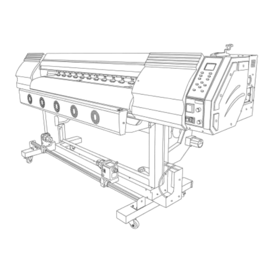
- Page 10 Chapter Two Details of Printer Framework of printer...
- Page 12 2Heads Color 6 Colors: Cyan, Magenta, Yellow, Black, LM ,LC Print head Resolution 1440dpi\2160dpi\2880dpi Injection 3~6 MM Distance Ink Type WIT-COLOR ink: Black, Cyan, Magenta, Yellow Continuously automatic ink supply Ink Supply Panel Heating: Temperature controller 30C°adjustable Heating System Heating Output Drying: 10~60C°adjustable...
-
Page 13: Installation Cautions
Power Supply Rated Frequency: 50Hz Rated Voltage: 220 AC(±10%) Power Max 1200W; Operating Power: 500W Dimension Length*Width*Height : 2.90*0.78*1.20m Weight 220kg Mode /h(2 heads) Output 4PASS 6PASS Installation Cautions Mechanical and Electronic Assembly Assembly printer from foot to body. Shrapnel and gasket must be attached to all the allen screw. - Page 14 Distinguish the front of the machine through screw hole. 2, Confirm the foot position, and then install the first crossbeam. 3, Install the second crossbeam and media collect motor.
- Page 15 4, Install media collect system. 5, Connect printer body and frame. The screw hole must correspond. 6, Open the right side cover and release the carriage. 7, Printer’s front view.
- Page 16 Install the tray to hold wasted ink box. 9, Insert ink cartridge: notice the position of needle and ink cartridge...
- Page 17 Do not tighten the screw until all the screws are ready. If the screw is sidetracked, please remove and screw again instead of pushing by force. Inspection 1, The connection of encoder sensor and encoder stripe shall be accurate as shown in the picture.
- Page 18 , Move carriage and calibrate printing panel. The distance from the carriage bottom to printing panel should be even from left to right. Adjustment can be made by propping up and pulling down the screws(marked with red in picture). 4, Make sure the ground wire is connected. 5, Check all cables' connections in PCBs and drivers.
- Page 19 ① Open the front protecting cover ② Check PCBs Check slot and interface. (Examples for your reference) If the slot or interface got loose, please tighten it and then close the cover.
- Page 20 6, Turn off all switches, and then connect the power supply cables. After turning on the Circuit Leakage Protector's Swith, then turn on the Main Power Supply. Self Inspection Printer’s auto self inspection will be performed when restarted. The process is below: Capping nozzles moving...
- Page 21 Second, the capping nozzle moves down till reaching the Optical Couple Switch. (If the motor runs in wrong direction or with noise, please check the motor cable's connections.) Third, the carriage moves to right till reaching the Optical Couple Switch. And then the carriage moves back to the left.
- Page 22 Installation of Printing Software and USB Drive Step 1: Connect USB data cable to printer and computer. The computer device manager will detect USB equipment. Step 2: Install software and printer driver Install printer driver, as you can’t operate the software without USB cable driver.
- Page 23 Device manager interface USB cabke driver installation Choose driver from the program file C:/program file/XP900printer/driver...
- Page 24 please click here If a dialogue window prop up as following picture, Please choose to yes.
- Page 25 Driver installation is completed. Step 3: Start the software and do the setting of the software Know well of software function and operate printer through software. Function of Printing Software Firstly, only after self inspection, USB connection, printer driver installation are completed, then you may operate in the software interface.
- Page 26 Secondly , all the software function will come into effect after connection. You may perform simple operations. 1, Media feeding and retreating, Print heads moving, Starting points settings 2, Cleaning function...
- Page 27 3, Printing function...
- Page 28 4, Selection of media type and speed 5, Setting 1 for improving printing effect Color bar to prevent nozzles from drying Automatic Printing clean...
- Page 29 6, Setting 2 for improving printing effect: Pass Optimization Feather Technology----to prevent overlapping or overstepping. 7, Software parameters setting as below photos...
- Page 32 Assembly of damper and print head Firstly, install damper. Secondly, install print head to the head plate...
- Page 34 Ink Cartridge Order on the printer...
- Page 36 Chapter Three Calibration of printer Adjustment of printer Menu-setting Physical Adjustment: the position of Capping Nozzle, Scraper and Print Head should be calibrated to make ink sucking and cleaning smoothly. Manual adjustment If the capping nozzles don’t align with print head’s nozzles, manual adjustment of capping unit could be made to keep them in a line.
- Page 37 Correct position of capping nozzles and print head’s nozzles Tips: When adjusting manually, please settle down the left capping nozzles, and then it’s easy to fix the right capping nozzles. Pump Intensity(Ink Sucking Power):...
- Page 38 How to improve printing effect Print Head Parallelism Calibration Click test and print one set of color swatch shown as picture, LM+K(2Heads) Y+LC(Right head) M+K (Left head) LC+K(2Heads) M+K (Left head) Y+LM(Right head) How to calibrate 1)The left two screws are for left head calibration,you need to adjust the Push or Pull screws to make M with K lines two in one as in above photo.
- Page 39 screws to make Y with LC and Y with LM lines two in one as in above photo. 3)The LM+K and LC+K lines are for checking whether the calibration of the two heads are good or not. Speed Setting(Carriage Delay Setting): Delay settings are made to avoid media feeding before carriage starts to move.
- Page 40 Print Heads'head space and Bidirectional Calibration Print Heads' head space Calibration: adjust the interval distance between two print heads. Find the M and K most mixed together lines and caculate the value above Example, the Line is -4 and 3 for down and up calibration. The original value is 7 and 6.
- Page 41 Go to Left to Right and Right to Left option and click test Find the most straight line and input the valve as above methord.
- Page 42 Media Feeding Calibration Calibration ① Decide the quantity of print heads when starting the software. ② Select feather option ③ Choose the media type and set a standard value for certain media. ④ 1 pass calibration, 1 pass motoring calibration. Click to test. The middle red line and black line should overlap.
- Page 43 The Third Party Software How to install Maintop software 1, Insert Maintop software dongle into the computer via USB port. 2, Put Maintop software CD into the computer CD-ROM. Automatically pop up setup window.( If your computer was installed with antivirus software to shield automatic pop-up function, please close it.) 3, Maintop software installation interface...
- Page 44 How to set up printer in maintop Step 1, enter “Maintop printing management system” Step 2, TCP/IP Port settings Select “Management” from “Menu” 1、Choose “Auto-RIP” “Auto-Print” 2、Config TCP/IP port Step 3, add a port, then modify the port properties.
- Page 45 ① Set IP address ② Set a RAW port IP address and RAM port shall be same with network settings of printing software. All the above completed, Maintop print management system will run in the background. How to set up printer in Maintop software...
- Page 46 Open the Maintop software,Setup Printer in maintop ① Open a new document with “New Folder” button ② Set up printer...
- Page 47 Click Custom Install,Browse the ULTRA9600-ECO ICC for maintop folder Click and set ULTRA 9600-ECO printer as default. Completed.
- Page 48 How to rip picture Lead in picture with shortcut key Picture alignment and paper setting Pictures alignment 1, Open “Align and distribution ” and “Picture information window ” Click the picture and then manifest the information.
- Page 49 2, The picture shall be fixed centered。 Decide the paper size on the basis of the picture size. How to print ① Print ② Resolution, port and paper settings ③ Choose resolution and paper type.
- Page 50 Resolution, port and paper settings ① “Printing resolution”: the resolution of output picture ② “Printing port”: RAW.127.0.0.1...
- Page 51 ③ “Media type”: banner, vinyl, PP etc. Click“Automatic media setting” to ensure the media size corresponding to the ④ picture size. All the above completed, you may print. Click “print to file” ,then input the file to ultra9200contral software,or click “ok” print it directly. Manual control panel instructions Function: In the absence of on-line computer, you may operate the panel to control carriage moving , media feeding, ink sucking, flashing and cleaning.
- Page 52 1. Connect: Connect the printer and computer. 2. Reset: Click and self inspect automatically. 3. Test: Test the nozzles’ status. Print heads’ working voltage should be triggered by printing software. 4. Stop: Stop ink sucking. 5. Clean: Clean print head automatically. 6.
- Page 53 Second, simple media feeding system Printing Operation Media feeding and media retreating Starting point settings...
- Page 54 Nozzles testing Nozzles cleaning Flash when the colors are mixed as shown in the following testing lines. Click and flash for seconds. Then click again to stop. Normal nozzles testing is as following. Ink sucking or cleaning Ink suck when the damper has no stock of ink. Clean when nozzles provide no ink.
- Page 55 Auto cleaning 1.Ink pump for seconds. 2. Carriage moves around. 3. Scraper wipes off the ink.
- Page 56 Printing Lead in printing files in .PRN/PRT format. Confirmation is necessary. If the picture size is larger than media size, please rip again.
-
Page 57: Problem Shooting
(The cable connection of new board and old board is different, please contact Wit-Color after-sales service department for support. ) 2.If the scraper fails to work due to the damaged motor, then you may need to change a new motor. -
Page 58: Printer Maintenance
Installation: The media shall be fixed on the media feeding bar by one person. Meanwhile, another person should stretch and align the media on the printing panel. If there still exists off-tracking problem, please contact Wit-Color after-sales service department. 3, If the size of actual printing and original picture is different, then you may adjustment of media feeding speed slightly. - Page 59 suction nozzle. Do not marinate the print head and suction nozzles in cleaning solution. During Printing 1、Turn on the power and then print color swatch. No block, no cleaning. 2、Check the alignment of bidirectional printing. 3、Check if there is sufficient ink in the damper. Use syringe when the ink is less than a half.
- Page 60 PCB Introduction...
Need help?
Do you have a question about the ULTRA 9600 and is the answer not in the manual?
Questions and answers