
Summary of Contents for Impac PI 6000
- Page 1 PI 6000 Programmregler Betriebsanleitung · User Manual IMPAC - Spezialist für berührungslose Temperaturmessung IMPAC - Specialist in non-contact thermometry...
-
Page 2: Table Of Contents
Programmregler PI 6000 Inhaltsverzeichnis Allgemeines ................................3 Informationen zur Betriebsanleitung ......................3 Haftung und Gewährleistung ........................3 Symbolerklärung / Bezeichnungen ....................... 3 Terminologie ..............................3 Urheberschutz .............................. 3 Entsorgung / Außerbetriebnahme......................... 4 Technische Daten ..............................4 Bestimmungsgemäße Verwendung......................5 Lieferumfang..............................5 Sicherheit.................................. -
Page 3: Allgemeines
Person über solche Änderungen zu informieren. IMPAC Infrared GmbH gibt auf das PI 6000 eine Gewährleistung von zwei Jahren ab Datum der Lieferung. Diese bezieht sich auf Fabrikationsfehler sowie Fehler, die sich während des Betriebes einstellen und auf einen Fehler der Firma IMPAC Infrared GmbH hinweisen. -
Page 4: Entsorgung / Außerbetriebnahme
Programmregler PI 6000 Entsorgung / Außerbetriebnahme Nicht mehr funktionsfähige IMPAC-Geräte sind gemäß den örtlichen Bestimmungen für Elektro- / Elektro- nikmaterial zu entsorgen. Technische Daten Messwert-Anzeige: 4-stellige 7-Segment-LED-Anzeige, 13 mm, rot Anzeige der Maßeinheit °C oder °F, 7 mm, rot Programm-Nr.-Anzeige: einstellige 7-Segment-LED-Anzeige, 13 mm, rot Stellgrößen-Anzeige:... -
Page 5: Bestimmungsgemäße Verwendung
(„Segmenten“) verwalten, der kontinuierliche Modus erlaubt auch Langzeitregelungen. Die Programmie- rung des PI 6000 erfolgt über einen PC, um ein versehentliches Verstellen der Eingaben durch den Anwen- der zu verhindern. Der eigentliche Regelbetrieb benötigt keinen PC, er wird direkt über die Tasten des PI 6000 gesteuert. -
Page 6: Wartungsarbeiten
Messpyrometer: Als Messwertaufnehmer wird ein digitales IMPAC-Pyrometer mit Analogausgang benötigt. Die Schnittstelle wird dabei für die Kommunikation des PI 6000 mit dem Pyrometer benutzt, der Analogaus- gang für die schnelle Übertragung des Messwertes. Die richtige Auswahl eines Pyrometers hängt vom Material des Messobjekts und der Messaufgabe ab. -
Page 7: Elektrische Anschlüsse An Der Geräterückseite
Durchgeschleift von 15 / 16 5.3.1 Spannungsversorgung Zum Betrieb des PI 6000 wird eine Spannung zwischen 18 und 30 V DC benötigt. Mit Anlegen der Spannungsversorgung ist das Gerät sofort betriebsbereit. Das Gerät besitzt keinen Ein/Ausschalter, so dass zum Ausschalten die Spannungsver- sorgung zu unterbrechen ist. -
Page 8: Anschluss Messpyrometer
4 / 5 Stromausgang 4-Leiter-Pyrometer 5.3.4 PC- bzw. SPS-Anschluss (RS232-Schnittstelle) Die Programmierung des PI 6000 ist nur über einen PC oder eine SPS möglich, der An- schluss erfolgt über eine RS232-Schnittstelle. 3 4 5 to PC 6 7 8 9 Um Erd- bzw. -
Page 9: Schaltausgänge
Programmregler PI 6000 5.3.5 Schaltausgänge Es stehen 4 Halbleiterrelais-Schaltausgänge safety shut-down (output) Verfügung (maximale Belastbarkeit ready (output) generator on (output) 50 V DC oder 36 V AC, 0,2 A). Diese können program start (output) z.B. zur automatischen Steuerung aufeinander folgender Regelvorgänge verwendet werden •... -
Page 10: Werkseinstellungen
Pyrometeranschluss Das PI 6000 benötigt zur Temperaturerkennung ein Messpyrometer (digitales IMPAC-Pyrometer der Serie 5, 12, 140, 510 oder 520), daher ist als erstes die Kommunikation zwischen diesem und dem PI 6000 zu über- prüfen. Ist das Pyrometer korrekt angeschlossen und erkannt, so verschwindet die Meldung „noPy“ auf der Anzeige und wird durch „- - - -“... -
Page 11: Programmstart
Schließen des Programms InfraWin Vorbereitung Bevor das Programm benutzt wird, ist zunächst unter Computer die RS232-Schnittstelle auszu- wählen, mit der das PI 6000 verbunden ist. Übersicht Programmierfenster Durch Anklicken dieses Feldes wird das Programmierfenster geöffnet, über das die Regel- programm-Erstellung des PI 6000 erfolgt. -
Page 12: Erste Schritte
Erreichen einer bestimmten Temperatur ausführen. Hinweis: Pyrometer der Serie 5 müssen über den Online/Offline-Schalter auf „Online“ gestellt werden, wenn die Kommunikation mit dem PI 6000 erfolgreich sein soll. Über das Fenster „Test / Auto Tune“ lassen sich automatisch Werte für die wichtigen Reg- leranteile Xp und Ki ermitteln, die dann manuell feinjustiert werden können, bis das ge-... - Page 13 Programmregler PI 6000 Kleine Hilfestellung zum Finden von optimalen Regelungsparametern für das PI 6000 Die PID-Parameter Grundsätzlich wird man bei einem thermischen Prozess unterschiedliche Regelparameter für unter- schiedliche Temperaturen ermitteln. Xp „Proportionalteil“ Xp ist eine dimensionslose Zahl, die den Kehrwert der Verstärkung des Reglers bedeutet.
-
Page 14: Messung (Online-Grafik)
Der Messbereich des angeschlossenen Pyrometers wird aber in der Titelzeile angezeigt. Das Übertragen der eingetragenen Werte aus der Programmoberfläche in das PI 6000 erfolgt mit einem Klick auf „Übernehmen“. Wird ein Regel-Programm gestartet, so werden alle Parameter in einer Zeile für die Regelung... -
Page 15: Programmablauf
Zeit fortgesetzt werden. Wird unter „t Segm“ „CONT“ eingegeben, so arbeitet der Regler kontinu- ierlich ohne Zeitbeschränkung. 6.6.4 Programmablauf Das Programm-Monitor-Fenster bietet die gleichen Möglichkeiten wie die Tastatur des Fortschrittsbalken PI 6000, es erlaubt das Starten, Stoppen oder Unterbrechen des jeweiligen eines Regelprogramms. Zusätzlich werden angezeigt: Segments • Soll- und Istwert Regleraktivitäts- •... -
Page 16: Weitere Programmeinstellungen
Daten wieder in das PI 6000 eingelesen werden. Inbetriebnahme / Bedienelemente / Anzeige am Gerät Ist die Programmierung abgeschlossen, kann das PI 6000 vom PC oder der SPS getrennt und als eigen- ständig laufendes Gerät verwendet werden, alle gespeicherten Regel-Programme können genauso, wie über den Programm-Monitor der Software, der Reihe nach aufgerufen, gestartet, gestoppt oder unterbrochen... -
Page 17: Übersicht
Hält ein laufendes Regel-Programm an (1x drücken) oder bricht es ab (2x drücken). (1x) Wird ein Regel-Programm angehalten, so wird die aktuelle Temperatur gehalten und das PI 6000 (2x) regelt weiter. Drücken der Starttaste setzt das Regel-Programm an der unterbrochenen Stelle fort. -
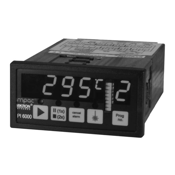
Page 18: Sonderanzeigen Auf Der Hauptanzeige
Pyrometer-Betriebsanleitung entnommen werden. Im Fenster der Pyrometer-Parameter befindet sich ein „Test“- Button. Dieser öffnet ein Fenster, das die direkte Kommunika- tion nur mit dem Pyrometer (nicht mit dem PI 6000) über die ® Schnittstellenbefehle ermöglicht (siehe UPP -Tabelle in der Anleitung des angeschlossenen Messpyrometers). -
Page 19: Messung (Online-Grafik)
Temperatur als grafische Darstellung • Aktuelle Messtemperatur • Sollwertvorgaben des Regelprogramms, wenn ein solches über das PI 6000 gestartet wurde • Anzahl der gemessenen Werte sowie die Dateigröße der aktuellen Messung Wird das Fenster direkt gestartet (also nicht in einem Regelprogramm über den Programm- Monitor bzw. -
Page 20: Grafik-Ausgabe (Auswertung)
Programmregler PI 6000 7.4.6 Grafik-Ausgabe (Auswertung) In der Grafik-Ausgabe wird die Kurve des Temperaturverlaufs über der Zeit im relevanten Messbereich dargestellt. Zusätzlich sind auf der rechten Seite des Fensters die der Messung zugrundeliegen- den Daten, sowie die Uhrzeit und Tempera-... -
Page 21: Datenformat Upp (Universelles Pyrometer-Protokoll)
Fall eines Fehlers mit "no" + CR. Jeder Befehl beginnt mit der 2-stelligen Geräte-Adresse (für PI 6000 immer "C0", großes "C" und Ziffer "0"), darauf folgen 2 Buchstaben für den Befehl (z.B. "ms" für Messwert). Darauf folgen, wenn benötigt, der oder die ASCII-Parameter "X". - Page 22 ...0..: immer 0 ..D..: Reglerausgang (vgl. Ya) ..D..: Analogeingang Alarmpyrometer (vgl. is) ..0..: immer 0 ..C0..: Geräteadresse PI 6000 (immer C0) ..D.: Baudrate PI 6000 ↔ Pyrometer (vgl. br) ..D: Tastensperre (vgl. lk) Gerätetyp / Software- C0ve Ausgabe: VVMMJJ VV = 81...
-
Page 23: Bestellnummern
Karton zu verwenden. Bei Überseeversand oder längerer Lagerung in hoher Luftfeuchtigkeit sollte das Gerät durch eine verschweißte Folie gegen Feuchtigkeit geschützt werden (evtl. Silicagel beilegen). Das PI 6000 ist für eine Lagertemperatur von -20 ... 70°C ausgelegt. Die Lagerung über oder unter dieser Temperatur kann zu Beschädigung oder Fehlfunktionen führen. -
Page 24: Stichwortverzeichnis
PC- bzw. SPS-Anschluss ........8 Anzeige am Gerät..........16 Programmablauf ..........15 ASCII-Datei............19 Programm-Fernsteuerung ........9 Programmierfenster ........... 11 Programmierumgebung ........10 Bedienelemente..........16, 17 Programmierung des PI 6000......10 Bestellnummern..........23 Pyrometer-Parameter ........18 Bestimmungsgemäße Verwendung .....5 Reglerausgang............. 9 RS232-Schnittstelle ..........8 Datenformat UPP ..........21... - Page 25 Programmable controller PI 6000 ontents General..................................26 Information about the user manual ......................26 Limit of liability and warranty........................26 Legend................................ 26 Terminology..............................26 Copyright ..............................26 Disposal / decommissioning ........................27 Technical data ................................ 27 Appropriate use ............................28 Scope of delivery ............................
-
Page 26: General
The PI 6000 from IMPAC Infrared GmbH has a warranty of two years from the invoice date. This warranty covers manufacturing defects and faults which arise during operation only if they are the result of defects caused by IMPAC Infrared GmbH. -
Page 27: Disposal / Decommissioning
Programmable controller PI 6000 Disposal / decommissioning Inoperable IMPAC controllers and pyrometers have to be disposed corresponding to the local regulations of electro or electronic material. Technical data Measured data display: 4-digit 7-segment LED display, 13 mm, red Display of the unit of measure °C or °F, 7 mm, red Program no. -
Page 28: Appropriate Use
Appropriate use The PI 6000 is a fast programmable PID controller that is optimised for use with an IMPAC series 5, 12, 50, 140, 510 or 520 digital pyrometer as a transducer and therefore provides an extremely fast controller cycle time of only 250 µs. -
Page 29: Maintenance
Measurement pyrometer: An IMPAC digital pyrometer with an analogue output is required as the trans- ducer. The interface is used for PI 6000 communication with the pyrometer, the analogue output for the fast transfer of the measured value. The correct selection of the pyrometer depends on the material from which the measured object is made and the measurement task. -
Page 30: Electrical Connections On The Rear Of The Unit
5.3.1 Power supply A voltage between 18 and 30 V DC is required to operate the PI 6000. The unit is ready for use immediately if connected to the power supply. The unit does not have an on/off switch; the power supply must be interrupted to switch off the unit. -
Page 31: Measurement Pyrometer Connection
4 / 5 Current output 4-wire pyrometer 5.3.4 PC or PLC connection (RS232 interface) It is only possible to program the PI 6000 using a PC or a PLC, the connection is made using an RS232 interface. 3 4 5 to PC... -
Page 32: Switched Outputs
Programmable controller PI 6000 5.3.5 Switched outputs Four semiconductor switched outputs are safety shut-down (output) available (maximum load 50 V DC or 36 V AC, ready (output) generator on (output) 0.2 A). These outputs can be used, e.g., for the... -
Page 33: Factory Settings
Pyrometer connection To measure the temperature the PI 6000 requires a measurement pyrometer (IMPAC series 5, 12, 140, 510 or 520 digital pyrometer), for this reason the communication between this pyrometer and the PI 6000 is to be checked first. -
Page 34: Starting The Program
(maximum two) Close the program InfraWin Preparation Before the program is used, the RS232 interface with which the PI 6000 is connected must first be selected using Computer. Overview of programming window Click this button to open the programming window that is used to prepare the control pro- gram for the PI 6000. -
Page 35: Getting Started
Note: Series 5 pyrometers must be set to "Online" using the Online/Offline switch for commu- nication with the PI 6000. Using the "Test / Auto Tune" window, you can automatically determine values for the impor- tant controller elements Xp and Ki; you can then manually fine tune the settings until the required result is obtained. - Page 36 Programmable controller PI 6000 Help with finding optimal control parameters for the PI 6000 The PID parameters In principle, different control parameters will be found for different temperatures in a thermal process. Xp "proportional element" Xp is a dimension-less number that represents the reciprocal of the gain of the controller.
-
Page 37: Measurement (Online Graph)
You can transfer the values from the programming window to the PI 6000 by clicking "Apply". When a control program is started, all parameters in a line are used for control and the segments are worked through in order. -
Page 38: Program Execution
Programmable controller PI 6000 The following entries can be made per segment: Desired temp.: The desired temperature can be selected as required within the limits for the pyrometer temperature range (set). The range can be seen in the title bar on the programming window if the pyrometer is connected. -
Page 39: Advanced Program Settings
Placing in operation / controls / display on the unit Once programming is complete, the PI 6000 can be disconnected from the PC or the PLC and used as a stand-alone unit, all control programs saved can be opened, started, stopped or interrupted in the same way as using the program monitor in the software. -
Page 40: Overview
Stop a control program that is running (press once) or cancel it (press twice). (1x) If a control program is stopped, the actual temperature is maintained and the PI 6000 continues to (2x) control the temperature. You can continue the control program from the point where it was inter- rupted by pressing the Start button. -
Page 41: Special Indications On The Main Display
The Pyrometer parameters windows contains a "Test" button. This button opens a window for direct communication only with the pyrometer (not with the PI 6000) using the interface ® commands (see UPP table in the instructions for the meas- urement pyrometer connected). -
Page 42: Measurement (Online Graph)
Test/AutoTune window) initially only the actual temperature from the measurement pyrometer is shown graphically. When a control program is started using the PI 6000, the desired values for the individual segments are also displayed. Other display features: •... -
Page 43: Graph Output (Analysis)
Programmable controller PI 6000 7.4.6 Graph output (analysis) The graph of the temperature over time in the related measur- ing range is displayed in the graph output. In addition, the data for the measurement as well as the time and temperature at the position of the vertical cursor line are also displayed on the right of the window;... -
Page 44: Upp Data Format (Universal Pyrometer Protocol)
"no" + CR. Every command starts with the 2-digit unit address (for PI 6000 always "C0", upper case "C" and digit "0"), followed by 2 letters for the command (e.g. "ms" for value measured). The ASCII parameter or parameters "X"... - Page 45 Programmable controller PI 6000 Write program de- C0XiXX ... XX XX ... XX = up to 32 characters of arbitrary text scriptive text (to describe the function of the program currently selected, available separately for each program) Read program de- C0Xi Read text (always 32 characters;...
-
Page 46: Reference Numbers
In case of shipment by sea or for extended storage in high atmospheric humidity, the unit should be pro- tected against moisture in a sealed plastic bag (if necessary add silica gel). The PI 6000 is designed for a storage temperature of -20 ... 70°C. Storage above or below this temperature may result in damage or malfunctions. -
Page 47: Index
Programmable controller PI 6000 Index Maintenance ............46 Measurement (colour bar) ......... 41 Measurement (online graph)......37, 42 Advanced program settings........39 Measurement pyrometer connection ....31 Alarm pyrometer connection.......31 Mechanical installation........29 Applying the values in the program ....37 Appropriate use ..........28 Assembling ............29... - Page 48 IMPAC Infrared GmbH Temperaturmessgeräte Kleyerstr. 90 D - 60326 Frankfurt/Main Tel.: +49 (0)69-9 73 73-0 Fax: +49 (0)69-9 73 73-167 E-Mail: info@impacinfrared.com Internet: www.impacinfrared.com 3 826 054-b...
Need help?
Do you have a question about the PI 6000 and is the answer not in the manual?
Questions and answers