Table of Contents
Advertisement
Advertisement
Table of Contents

Subscribe to Our Youtube Channel
Related Manuals for NAD C 565BEE


Summary of Contents for NAD C 565BEE
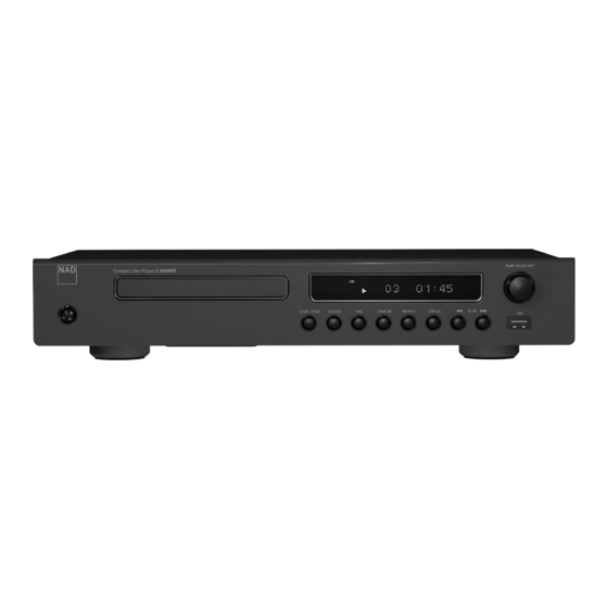
- Page 1 C 565BEE COMPACT DISC PLAYER...
-
Page 2: Safety Information
SAFETY INFORMATION CAUTION CLASS 1 LASER PRODUCT The lightning flash with arrowhead, within an equilateral tri- The exclamation point within an equilateral triangle is intend- angle is intended to alert the user of the presence of ed to alert the user of the presence of important operating uninsulated "dangerous voltage"... -
Page 3: Table Of Contents
SERVICE SAFETY PRECAUTIONS Replacing the fuses CAUTION: FOR CONTINUED PROTECTION AGAINST THE RISK OF FIRE REPLACE ONLY WITH SAME TYPE OF FUSE. Reference No Part Number Description 5120-0050+0 FUSE T1.6A/250V 5X20 FC200 5120-0018+0 FUSE T1A 250V 5X20 FC201, FC202 5120-0035+0 FU T100MA 250V FC203 5120-0018+0... -
Page 4: Specifications
SPECIFICATIONS GENERAL PARAMETERS Output level - Analog 2.2 ± 0.1 V Optical -22.5 ± 3.5 dBm Coaxial 650 ± 150 mV Frequency response ± 0.3 dB (ref. 0 dB 20 Hz-1 kHz) ± 0.5 dB (ref. 0 dB 5 kHz-20 kHz) Total harmonic distortion <... -
Page 5: Rear Panel / Front Panel
REAR PANEL / FRONT PANEL REAR PANEL LINE OUT +12V TRIGGER INPUT RS232 IR IN DIGITAL AUDIO IN (OPTICAL) AC MAINS INPUT DIGITAL OUT (COAXIAL, OPTICAL) FRONT PANEL STANDBY BUTTON REPEAT STANDBY LED DISPLAY DISC TRAY 10. SCAN STOP/OPEN 11. USB INPUT SOURCE 12. -
Page 6: Disassembly Instructions
DISASSEMBLY INSTRUCTIONS 1. Remove machine screws M 4.0 x 6.0 ( 1 to 4 ) from the side panels. Remove tapping screw 3.0 x 8.5 ( 5 )from the back panel. Refer to Figure No.1. Figure No.1 2. Pull both sides of the TOP COVER slightly outwards 6 and tilt approx. 35˚ and then remove in the direction as indicated by the arrow 7 . -
Page 7: Block Diagram
BLOCK DIAGRAM - 7 -... -
Page 8: Wiring Diagram
WIRING DIAGRAM 7013-049520+0 7013-0550+0 part of front panel part of front panel 7013-0510+0 7012-9020+0 7013-0520+0 7013-0560+0 7013-1280+0 7013-0600+0 7012-9450+0 CORD-AC UL/CSA 125V 10A - For AH Version 7012-9470+0 CORD-AC PWR CE 250V 10A - For C Version - 8 -... -
Page 9: Rf Pattern Testing
RF PATTERN TESTING NAD - C 565BEE PCB TESTING POINTS DIAGRAM TESTING PROCEDURE (1) Load the test disc (Sony Test CD YEDS-7) and set the unit into PLAY mode. (2) Connect the scope to C7 (Pin 81 of IC1) and DGND (C32). -
Page 10: Important Notes
IMPORTANT NOTES INSTRUCTION FOR HANDLING OPTICAL SYSTEM BLOCK PICK-UP Electrostatic breakdown of the laser diode in the optical system block may occur due to a potential difference caused by electrostatic charge accumulated on clothing, human body, etc. A ground must be provided as follows to prevent any electrostatic charge during unpacking or repair work. - Page 11 PRECAUTIONS WHEN CHANGING LASER PICK-UP When removing the pick-up assembly, short circuit the PCB tracks on the optical block as show in the drawing in order to protect the pick-up before removal. NOTE: Replacement pick-up assemblies are supplied with the PCB pattern already protected. DO NOT REMOVE THE SHORT CIRCUITS UNTIL YOU HAVE FINISHED FITTING THE PICK-UP.
- Page 12 MULTI-KEY TABLE FOR C565BEE (original production) Item Content Multi-key SRC + SCAN BACK VFD full segment display RANDOM + SCAN FORWARD Playtime total RANDOM + SCAN BACK Eject times count NOTES New special key functions (MCU v1.3.8. & Servo v4.4.) -Playtime total counter : Random + Scan Back for 5 sec.
- Page 13 NOTES - 13 -...
-
Page 14: Pcb Layout
PCB LAYOUT MAIN BOARD - top side - 14 -... - Page 15 MAIN BOARD - bottom side - 15 -...
- Page 16 POWER BOARD VOL BOARD top side bottom side LED BOARD top side bottom side USB BOARD top side bottom side top side bottom side VFD BOARD top side bottom side - 16 -...
- Page 17 SERVO BOARD top side bottom side - 17 -...
-
Page 18: Schematic Diagram
SCHEMATIC DIAGRAM L214 600R/100MHz C372 C373 DGND R451 IC213-B 74HC125 24.576MHz R455 MCLK C371 R449 C374 U217 R450 DGND DGND C370 U218 IC213-A 74HC125 22.5792MHz R448 MUTE DA_MUTE CLK_SEL R326 BC846B Q223 R221 DGND U210 POWER SELECT R254 LRCLK R268 WM874X_CS LRCLK CSB/SADDR/I2S... - Page 19 MCU, RS232, TRIGGER IN, IR IN CPU_5V C245 C246 U203-C 10uF/25V LM393 DGND R288 R289 +12V IC212 C238 1 A1 R282 R274 R460 330R J202 NC/0R R280 U216 2 B1 RS232 FEMALE DAP202 IR IN DGND 3 Y1 200R U203-A L215 REMOTE J300...
- Page 20 POWER CPU_5V ECO NO: R300 R429 R428 Q221 1N4148 RELAY D220 BC846B Q213 C380 HS200 BC846B B7B-PH-K-S D5V6 LM7806 U207 R228 NC/7K5 RL202 1CH RELAY C266 C268 C267 C269 C216 R229 220uF/16V 470uF/16V 7.7uH 0R/1K C252 L207 2200P/400V AC203 DGND HS207 To servo HS_GPE_5400-1706+0...
- Page 21 VFD101 F1_4.1V FAC1 Q142 FAC2 F2_4.1V R146 C147 DTC114SE 47pF -F28V VEE_-28v D143 Z101 R144 R143 R155 1N4148 470R 470R 5.6V C146 FGND 47pF CON142 FAC1 FAC1 PLAY R156 R157 FAC2 FAC2 FGND -F28V -F28V R145 470R R147 R148 R149 R150 KEY1 VKEY0...
- Page 22 SERVO NOTE: 1. RESISTORS, ARE CARBON FILM 5% 1/8W UNLESS OTHERWISE SPECIFIED. 2. CERAMIC CAPACITORS, ARE 50V 10%. UNLESS OTHERWISE SPECIFIED. - 22 -...
- Page 23 NOTE: 1. RESISTORS, ARE CARBON FILM 5% 1/8W UNLESS OTHERWISE SPECIFIED. 2. CERAMIC CAPACITORS, ARE 50V 10%. UNLESS OTHERWISE SPECIFIED. - 23 -...
-
Page 24: Ic Block Diagram
IC BLOCK DIAGRAM MAIN BOARD MAIN BOARD IC200: LM809M3-3.08/NOP IC202, IC203: REG NCP1117ST33T3G 1 2 3 (Top View) Pin: 1. Adjust/Ground 2. Output 3. Input MAIN BOARD IC201: NVP1117ST18T3G MAIN BOARD MAIN BOARD IC204, IC211, U208: NJM7805FA-#ZZZB IC212: QUAD 2INPUT EXCLUSIVE U204: NJM7812FA-#ZZZB U207: 6V 3-TERMINAL REGULATOR 7800FA - 24 -... - Page 25 MAIN BOARD IC205: DSP SRC4382 TDFP-48 - 25 -...
- Page 26 MAIN BOARD IC206: MCU TMP86FS49AUG (INT3/TC2) P15 P74(AIN12) /TC5) P16 PDO5/PWM5 P73(AIN11) /TC6) P17 PDO6/PWM6/PPG6 P72(AIN10) (SCL) P50 P71(AIN9) (SDA) P51 P70(AIN8) P67(AIN7/STOP3) P66(AIN6/STOP2) P65(AIN5/STOP1) P64(AIN4/STOP0) P63(AIN3) P62(AIN2) P61(AIN1) P60(AIN0) AVDD VAREF P07(INT2) - 26 -...
- Page 27 MAIN BOARD IC207: MEMORY 24C1024 SOIC8 MAIN BOARD IC209: REGULATOR TA48015F SERVOR BOARD IC3: REGULATOR TA48015F Overcurrent- Constant limiting circuit current circuit Reference voltage circuit Overheating detection circuit - 27 -...
- Page 28 MAIN BOARD U202: TA7291SG(5/M)22240239 MAIN BOARD MAIN BOARD U203: LM393MNOPB U205: NJM7912FA-#ZZZB Output 1 Output 2 Inverting input 1 Non-inverting input 1 Inverting input 2 Non-inverting input 2 MAIN BOARD MAIN BOARD U210: QUAD BUFFER U212, U213: OPA2134UA/2K5 Out A –In A Out B +In A...
- Page 29 POWER BOARD D230: ADJUST SHUNT REG CATHODE(K) CATHODE REFERENCE REFERENCE (R) 2.5V ANODE(A) ANODE POWER BOARD U201: POWER NCP1014 Startup Source Iref = 7.4 mA 8 GND Drain Vclamp* 7 GND Rsense High when V UVLO 250 ns Management L.E.B. 5 DRAIN Reset 65, 100 or...
- Page 30 SERVO BOARD IC1: DSP TC94A73MFG - 30 -...
- Page 31 SERVO BOARD IC5: MCU TMP92FD28A RESET PC0/INT0 DVSS PC1/INT1 PC2/INT2/TB1IN0/TB0IN0 PC3/INT3 P83/CS3/WAIT/TA5OUT DVCC3B P82/CS2 P80/CS0/TA1OUT/BOOT P74/TA0IN P73/SRLUB DVSS P72/SRLLB TMP92FD28AFG DVCC1B P71/SRWR RVOUT1 P70/RD LQFP100 RVIN DVCC3A RVIN DVSS TOPVIEW RVOUT2 P67/A23 DVCC1A P66/A22 DVSS P65/A21 P00/D0 P64/A20 P01/D1 P63/A19 P02/D2 P62/A18 P03/D3...
- Page 32 SERVO BOARD IC8: REGULATOR TA4805F SMD Over current Constant protection current circuit Reference voltage circuit Thermal shutdown circuit SERVO BOARD IC10: MEMORY EPROM SERVO BOARD IC77: LM1117S-3.3 μ - 32 -...
- Page 33 SERVO BOARD U2: MOTOR DRV W/3.3V REG - 33 -...
-
Page 34: Troubleshooting Guide
TROUBLESHOOTING GUIDE - 34 -... -
Page 35: Electrical Parts List
ELECTRICAL PARTS LIST Location Part Number Description LED ASSY SVC-C56516+LED PCB ASSY LED part of fascia PC BOARD 1725-982A+0001 PCB MAIN/VFD/USB/PWR/VOL D WAFER/SOCKETS CON141A 2102-040R+J01 WAFER 4P P2.0 90DEG TRANSISTOR Q141 4858-46B0+3 TR BC846B SOT23 PHILIPS RESISTOR R141 4723-472A+P RMG 1/16W 4.7K 1%. R142 4723-122A+P RMG 1/16W 1.2K 1% 0603... - Page 36 Location Part Number Description C207 157D-107M+K-IUE CE 16V 100U 20% RLT 5X11 C208, C209 150F-104K+P-AC CC 50V 0.1uF 10% C210 157D-476M+K-IME CE 16V 47U 20% RLT 5X7 C211, C212, C213, C214 157D-106M+5-IUF3 CE 16V 10uF 20% RL 5X11 C215, C216 150F-104K+P-AC CC 50V 0.1uF 10% C217...
- Page 37 Location Part Number Description C275 157F-476M+K-LUTI CE 50V 47U 20% RLT C276 150F-104K+P-AC CC 50V 0.1uF 10% C277 157F-476M+K-LUTI CE 50V 47U 20% RLT C278, C279, C280, C281 150F-104K+P-AC CC 50V 0.1uF 10% C282 157D-106M+K-IUE CE 16V 10U 20% RLT 5X11 C283 150F-104K+P-AC CC 50V 0.1uF 10%...
- Page 38 Location Part Number Description C349 150F-104K+P-AC CC 50V 0.1uF 10% C350 157D-108M+K-S9TU CE 16V 1000U 20% RLT C351 150F-104K+P-AC CC 50V 0.1uF 10% C352 157D-108M+K-S9TU CE 16V 1000U 20% RLT C353 150F-103J+P-AC CC 50V 0.01U 5% 0603 C354 157D-107M+K-IUE CE 16V 100U 20% RLT 5X11 C355, C356, C357, C358 15CH-220J+P-AC CTC 0/60 22pF 5% 0603...
- Page 39 Location Part Number Description WAFER/SOCKET AC201 2101-1432+0 WAFER 2P P7.92 JAPAN J200 2101-9400+0 JM2422-3M WAFER J203 2101-3149+0 CONNECTOR FFC 15P P1.25 J209 2102-040S+003 WAFER 4P P2.0 STRAIGHT J210 2102-030S+003 3P ST.WAFER P=2.0 J211 2102-080S+003 8P ST. WAFER P=2.0 JP222 2102-040S+003 WAFER 4P P2.0 STRAIGHT SW200 2101-1495+0...
- Page 40 Location Part Number Description RESISTOR R210, R276, R317, R319, R322, R423, R455, R456, 4723-000J+P-R RMG 1/16W 0R 5% 0603 R457, R463, R474 R203, R208, R209, R214, R215, R220, R221, R222, 4723-103A+P-R RMG 1/16W 10K 1% 0603 R223, R226, R232, R238, R239, R240, R241, R242, R243, R244, R247, R250, R251, R252, R253, R263, R271, R279, R283, R287, R288, R289, R295, R296, R297, R332, R342, R343, R344, R345, R346, R349,...
- Page 41 Location Part Number Description R293 4723-220A+P RMG 1/16W 22R 1% 0603 R298 4723-222A+P RMG 1/16W 2.2K 1% R300 4723-202A+P RMG 1/16W 2K 1% R302 4723-100A+P-R RMG 1/16W 10R 1% 0603 R308, R309, R310 4723-220A+P RMG 1/16W 22R 1% 0603 R311 4723-202A+P RMG 1/16W 2K 1% R312, R313, R314, R315...
- Page 42 Location Part Number Description R477 4723-000A+P RMG 1/16W 0R 1% 0603 R478 4723-101A+P RMG 1/16W 100R 1% 0603 R481 4723-102A+P RMG 1/16W 1K 1% IC200 3132-2561+0 IC LM809M3-3.08/NOPB IC201 3132-0380+0 IC NCP1117ST18T3G IC202, IC203 3132-1481+0 IC REG NCP1117ST33T3G IC204, IC211 3130-2020+2 IC NJM7805FA-#ZZZB IC205...
- Page 43 Location Part Number Description D221 481X-147L+2 PHOTO RECEIVER TORX147L D222 481T-X147+2 PHOTO TRANSMITTER F200, F201, F202, F203, F204, F205, F206, F207, F208, 4131-9131+0 FUSE HOLDER 6.5MM PITCH F209 HS200 5400-9132+0 HEATSINK 7805 2438-17 IC206 3000-9812+0 BLANK LABEL (5X10) IC206-A 312A-0580+01 SOFTWARE MCU V1.3.3 J201 2101-3233+0...
- Page 44 Location Part Number Description WAFER/SOCKET AC200 2101-1432+0 WAFER 2P P7.92 JAPAN COIL L203 1807-273J+PS COIL 27MH 5% 8.3X9.7 L207 1806-4041+0000 CHOKE COIL 7.7MH 10% RELAY RL200 4500-0762+0 RELAY 5VDC 10A SPDT RL205 4500-0753+0 RELAY 5VDC 1A DPDT BP-5 TRANSISTOR Q206, Q208 4858-46B0+3 TR BC846B SOT23 PHILIPS RESISTOR...
- Page 45 Location Part Number Description CAPACITOR C395 150F-103J+P-AC CC 50V 0.01U 5% 0603 JACK/SOCKET JP107 2113-3205+0 SOCKET USB USB-A-S-01 MISCELLANEOUS JP108 7013-0601+0 WIRE-SHILED 4P P2.0 #24 L222 1808-0887+0 FERRITE BEAD 1.25X2 0805 VFD ASSY SVC-C56516+VFD PCB ASSY VFD part of fascia PC BOARD 1725-982A+0001 PCB MAIN/VFD/USB/PWR/VOL D...
- Page 46 Location Part Number Description R148 4723-222A+P RMG 1/16W 2.2K 1% R149 4723-682A+P RMG 1/16W 6.8K 1% R150 4723-303A+P RMG 1/16W 30K 1% R151 4723-751A+P RMG 1/16W 750R 1% 0603 R152 4723-222A+P RMG 1/16W 2.2K 1% R153 4723-682A+P RMG 1/16W 6.8K 1% R154 4723-303A+P RMG 1/16W 30K 1%...
- Page 47 Location Part Number Description SERVO ASSY SVC-C56516+SERVO PCB ASSY SERVO PC BOARD 1725-970A+0001 PCB SERVO BOARD D/S FR-4 CAPACITOR C1, C10, C11, C12, C13, C14, C15, C16, C17, C18, C19, 150F-104K+P-AC CC 50V 0.1uF 10% C2, C20, C21, C22, C23, C24, C25, C26, C27, C28, C29, C3 C30, C31 157D-226M+K-IU...
- Page 48 Location Part Number Description 150F-104K+P-AC CC 50V 0.1uF 10% 157D-107M+K-IUI CE 16V 100UF 20% RLT 157D-107M+K-LUTU CE 16V 100U 20% RLT C9, C90 150F-104K+P-AC CC 50V 0.1uF 10% 157D-107M+K-LUTU CE 16V 100U 20% RLT 157D-476M+K-IU CE 16V 47U 20% RLT 5X11 150F-104K+P-AC CC 50V 0.1uF 10% 157D-107M+K-LUTU...
- Page 49 Location Part Number Description R10, R37, R38 4723-104A+P-R RMG 1/16W 100K 1% 0603 4723-223A+P-R RMG 1/16W 22K 1% 0603 4723-471A+P-R RMG 1/16W 470R 1% 0603 R100, R101, R102, R103, R46, R5, R96, R97, R98, R99 4723-473A+P-R RMG 1/16W 47K 1% 0603 4723-560J+P-R RMG 1/16W 56R 5% 0603 JP1, JP15...
- Page 50 Location Part Number Description IC77 3132-2821+0 IC LM1117S-3.3 3132-6720+0 IC REGULATOR TA4805F SMD 3132-3231+0 IC MOTOR DRV W/3.3V REG MISCELLANEOUS 3000-9812+0 BLANK LABEL (5X10) IC5-A 312A-0520+01 SOFTWARE SERVO MCU V4.0 D 2101-3102+0 CONNECTOR FFC 16PIN P1.0 1803-0055+0 INDUCTOR CHIP 10UH NOTE: The components identified by mark are critical for risk of fire and electrical shock.
-
Page 51: Mechanism Exploded View
MECHANISM EXPLODED VIEW DA11VZ - 51 -... -
Page 52: Mechanism Exploded View Parts List
MECHANISM EXPLODED VIEW PARTS LIST Item Part No. Description ASSY, LASER, CDM DA11VZ ASSY, MOTOR, SPINDLE ASSY, MOTOR, SLED CHASSIS COVER, REAR SAHFT, SLIDE GEAR, MIDDLE GEAR, DRIVE SWITCH, LEAF CONNECTOR-6P MOTOR SPECIAL SCREW M2.0uP.0 SPECIAL SCREW M2.6u6.0 - 52 -... -
Page 53: Exploded View
EXPLODED VIEW - 53 -... -
Page 54: Exploded View Parts List
EXPLODED VIEW PARTS LIST Item Part No. Description Q’ty SVC-C56517+FASC PANEL-FRONT AL fascia assembly with cables 0101 * Grey SVC-C56516+FASC PANEL-FRONT AL fascia assembly with cables 0101 * Titanium FRAME-FRONT NSP 0102 * Grey 1468-5302+1 FRAME-FRONT NSP 0102 * Titanium 1468-5301+1 FRONT LENS NSP 0103... - Page 55 Item Part No. Description Q’ty 0222 2904-3005+3000 SCREW M3X5 0225 1454-2620+0 TRANFORMER COVER 0301 * Grey 1402-3534+0 TOP COVER 0301 * Titanium 1402-3532+0 TOP COVER 0302 * Grey 2900-4006+3010 SCREW PW M4X6 0302 * Titanium 2900-4006+2010 SCREW PW M4X6 0303 * Grey 2954-3010+3000 SCREW 3X10 TAP...
-
Page 56: Packing Diagram
LABEL BARCODE AH GREY 3001-2308+0 LABEL BARCODE C TITITANIUM 3001-2309+0 LABEL BARCODE C GREY Proprietary information for servicing purposes only. The information herein may not be used com- mercially without the prior written agreement of NAD Electronics International, Toronto, Canada. - 56 -...
Need help?
Do you have a question about the C 565BEE and is the answer not in the manual?
Questions and answers