Table of Contents
Advertisement
Quick Links
Advertisement
Table of Contents

Summary of Contents for Oz inventions XPRESSION FX Black Magic Motion
- Page 1 Modulator - Receiver User guide...
-
Page 2: Table Of Contents
Display in normal use mode ........................20 Indicator lights in normal use mode ......................20 Display in menu mode ...........................20 Indicator lights in menu mode .......................20 Menu ................................21 Menu access and control........................21 System menu items ..........................23 ADSR items ............................29 © Oz inventions Version 1.8... - Page 3 Playback / Record ..........................53 Using the modulator as a foot switch ......................54 Default settings ............................55 Menu item order ............................56 Step size settings for various devices......................57 A final note ...............................58 Trouble shooting ............................59 Modulator-Receiver specifications ......................60 Index.................................61 © Oz inventions Version 1.8...
- Page 4 © Oz inventions Version 1.8...
-
Page 5: Declaration Of Compliance
Manufacturer’s address: PO Box 86, Warrnambool, Victoria. 3280 Declares that the product Product name: Xpression fX Black Magic Motion (Modulator) is compliant with the following standards regarding radiated and conductive emissions relevant to this product and Electro Magnetic compatibility. ... -
Page 6: Please Read These Two Very Important Messages
Manufacturer Polarity Resistance (Kohm) Arturia® Boss® Digitech® Eleven rack® Line 6® M-Audio® Mooger Fooger® Pigtronix® Strymon® TC Electronic® TC Helicon® Yamaha® Zoom® Figure 1 – Common polarity and resistance settings © Oz inventions Version 1.8... -
Page 7: Provided Items
5 volts. Damage can be caused to this modulating device if greater than 5 volts is applied to the expression socket. Consideration must be taken when connecting and using it. If in doubt contact Oz inventions at contact@ozinventions.com ©... -
Page 8: Warranty
The device is warranted for use in Australia. If the product is defective as a result of faulty workmanship or materials, Oz Inventions will at their discretion repair or replace the product for a period of 12 months from purchase. -
Page 9: Introduction
Introduction Xpression fX Black Magic Motion from Oz Inventions, is a wireless motion controlled audio effects controller. It is designed for use with effects units, keyboards and MIDI controllers that have an expression pedal socket, sometimes called a control socket. -
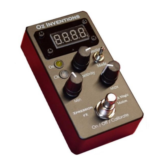
Page 10: Controls And Sockets Overview
= Record armed; Continuous slow flashing = Recording in progress. Sensitivity – sets response time, stability, playback time and other parameters dependent on the chosen modulation mode DC power jack –2.1mm; 9 – 12V; 150mA; Negative centre © Oz inventions Version 1.8... -
Page 11: Connecting
Figure 4 – Connecting the expression jack The plug/socket connection is firm and should click as it is made. The plug should be pushed in until all of the silver plating is inside the socket. © Oz inventions Version 1.8... -
Page 12: Connecting The Dc Power Adapter
Best reception is found when the antenna is bent at a 90 degree angle (vertical). However, slanting the antenna back a few degrees may have an insignificant impact on reception and has the advantage of being more tolerant to accidental damage. Figure 8 – Angle the antenna back slightly © Oz inventions Version 1.8... -
Page 13: Connecting Multiple Receivers
Setting multiple sensor-transmitters and receivers to different channels is also possible and offers many combinations and possibilities. The picture below shows two sensor-transmitters on different channels. Sensors can be attached to anything that moves. E.g. guitar, arm, leg, drummer, dancer etc Figure 10 -= Many possibilities © Oz inventions Version 1.8... -
Page 14: Main Indicator Lights
Indicator lights in menu mode An illuminated dot under the last character, signifies that the menu is currently being accessed. An illuminated dot under the first character signifies that the current menu item is an ADSR item. © Oz inventions Version 1.8... -
Page 15: Controls
This mode is designed for rotational movement such as side to side swaying or swinging, as maybe done when playing a guitar, dancing or other circular movement. Calibration is usually required before use. See Rotation calibration process pg 30 The bidirectional switch allows a continuous circle © Oz inventions Version 1.8... - Page 16 Plays the ADSR envelope as set within the ADSR menu See Understanding ADSR, Automatic ADSR mode and ADSR trigger mode Playback recorded ADSR (P) Plays the recorded ADSR envelope as recorded in record mode. See Understanding recording pg 37 © Oz inventions Version 1.8...
-
Page 17: Bidirectional Switch
The sensitivity control in quad tilt mode also enables effective retriggering of the ADSR envelope. The zero point is needed for retriggering and is difficult to locate when there is only a small zero point window available. © Oz inventions Version 1.8... -
Page 18: Min Depth (0 - 127)
For example, when maximum depth is set to 90, modulation cannot go higher than 90. For example, if the chosen effect parameter to be modulated is ‘volume’ with a range from no volume at 0, to maximum © Oz inventions Version 1.8... - Page 19 If it is in the wrong position, the result can be no modulating output. Whenever a menu is exited, be sure to correctly place the maximum depth control. If at any time modulation is not working as expected, check the maximum depth control, and also the minimum depth control and the sensitivity control. © Oz inventions Version 1.8...
-
Page 20: Display
Indicator lights in menu mode An illuminated dot under the last character, signifies that the menu is currently being accessed. An additional illuminated dot under the first character signifies that the current menu item is an ADSR item. © Oz inventions Version 1.8... -
Page 21: Menu
(0) and rotating the minimum depth control fully clockwise (127). The presets can then be changed by pulling forward the modulation mode toggle switch. To exit preset selection, change the minimum or maximum depth control to any position. © Oz inventions Version 1.8... - Page 22 After menu exit, It is important to return the depth controls to the position they were in before menu entry System reset System reset is actuated by holding the modulation mode switch forward, whilst applying power, and then releasing the switch. © Oz inventions Version 1.8...
-
Page 23: System Menu Items
127. Increasing the minimum control will increase the beginning modulation above 0. AtrG (ADSR trigger mode) The ADSR envelope will be triggered on and off by the modulating output, as per the ADSR trigger settings in the menu. © Oz inventions Version 1.8... - Page 24 Automatic cutoff Default – 2 seconds; Range – 0 – 99 seconds The automatic cut-off parameter determines how long after transmission ceases, the modulating output will reduce to zero. A setting of ‘0’ has no cut-off. © Oz inventions Version 1.8...
- Page 25 A varying voltage returns from the ring. Tip, Sleeve. The ring is disconnected. A varying voltage comes through the tip. Depending on the effects unit/keyboard/MIDI controller, TS polarity may enable the modulator to function as a foot switch © Oz inventions Version 1.8...
- Page 26 Linear gives an even rise Log gives an initial fast rise that slows down as it approaches the end Anti-log gives an initial slow rise that speeds up as it approaches the end Linear Logarithmic Anti-Logarithmic (Inverse) © Oz inventions Version 1.8...
- Page 27 When the system menu is exited, the settings will be saved or not, dependant on this setting. The parameter is always set to ‘quit’ when a menu is accessed. The parameter must be purposely changed to ‘Save’ even after ‘Save’ has been selected previously. © Oz inventions Version 1.8...
- Page 28 Save The menu is exited and all settings for all presets, including calibration, system settings and the current modulation mode, are saved. When the device is powered off and on, the settings are retained. © Oz inventions Version 1.8...
-
Page 29: Adsr Items
Sustain Time (St) Default – 5; Range 1 – 99 The sustain time is the period of time between the decay rate finishing and the release rate starting. © Oz inventions Version 1.8... - Page 30 The ADSR envelope is triggered when the modulating output reaching its maximum as set by the maximum depth control (1 – 127). The envelope plays continuously until the modulation output reaches the minimum depth as set by the minimum depth control. © Oz inventions Version 1.8...
-
Page 31: System Reset
The display will show ‘rst-‘ Releasing the modulation mode switch will restore default settings and reboot the device Alternatively, removing power whilst the switch is still held will retain the stored settings. © Oz inventions Version 1.8... -
Page 32: Step Size Menu Items
In these modes the depth controls display 1 – 16 for the 16 available steps, rather than the usual 0 – 127. The maximum depth control also adjusts the timing between the last rising and first falling step. © Oz inventions Version 1.8... -
Page 33: Preset Selection
Presets enable quick changes between different customisable step sizes Presets enable quick changes between different calibration settings Upon first powering up the unit after manufacture, all presets will have the same default values (pg 55) © Oz inventions Version 1.8... -
Page 34: Calibration
3. Continue to hold the button and move the sensor-transmitter to the finishing position 4. Release the button. The angle end has now been set and modulation will be at maximum at that point. © Oz inventions Version 1.8... -
Page 35: Tilt And Quad Tilt, Calibration Process
When the finishing position is exceeded the display will remain at 127. When the direction is changed back toward the starting position, the display will start to decrease immediately and so does not wait until the initial finishing position is reached. © Oz inventions Version 1.8... - Page 36 Best operation is obtained when the sensor is held on the plane on which it started, though good results can still be obtained should the sensor tilt during operation. © Oz inventions Version 1.8...
-
Page 37: Understanding Recording And Playback Modes
Fully anti-clockwise (0) is no trim. Fully clock-wise trims the entire recording, leaving nothing left to play and so no modulation. Initially in playback mode start with the trim control fully anti-clockwise so you can hear the entire recording, and then work toward clockwise to remove the trailing section/s. © Oz inventions Version 1.8... -
Page 38: Recording Process
**The minimum depth control can also be used to trigger recording and can be used to control the waveform to be recorded, rather than using the sensor module. © Oz inventions Version 1.8... -
Page 39: Modulation Modes
Best results are obtained when calibration begins in one of these orientations and ends before entering another orientation. However, greater than 90 degrees can be calibrated and the calibration does not need to begin or end in the ideal orientations, rather these are ideal orientations that will provide best results. © Oz inventions Version 1.8... - Page 40 The default settings are zero when the device is Figure 16 –First direction Figure 17 –Second direction horizontal with the ground and 127 when it is tilted 90 degrees backward. © Oz inventions Version 1.8...
-
Page 41: Understanding Quad Tilt Mode
Figure 14 – Zero point window with sensitivity at 0 Figure 15 – Zero point window with sensitivity at 5 As with tilt mode, there are six best orientations from which calibration should start. © Oz inventions Version 1.8... - Page 42 9. Tilt the sensor left, right, forward and backwards and the display will change accordingly. 10. Notice that the values that were reading from 1 – 9 are now all reading 0, effectively expanding the zero point window. © Oz inventions Version 1.8...
-
Page 43: Understanding Rotation Mode And Guitar-Hand Mode
The same effect occurs at the zero degree point. When the bidirectional switch is activated the output will continue in a circle rather than cutting off at 0 and 127, as shown in the picture here. © Oz inventions Version 1.8... -
Page 44: Understanding Velocity Mode
10. Adjust the sensitivity if the speed is not registering on the display Straight line movements as well as circular movements are able to be made, with circular movements creating a stronger reaction and hence require lower sensitivity settings. © Oz inventions Version 1.8... -
Page 45: Understanding Flick Mode
7. Adjust the sensitivity control so that a flick of the sensor creates the maximum modulating output (127) 8. Flick mode works well as a trigger for the ADSR envelope. See ADSR trigger mode pg 48 © Oz inventions Version 1.8... -
Page 46: Understanding Adsr, Automatic Adsr Mode And Adsr Trigger Mode
Figure 20 – Shot duration envelope Not all sections of the ADSR envelope need to be used. The picture below shows only the attack and decay sections in use. Figure 21 – Limited section envelope © Oz inventions Version 1.8... - Page 47 As a final example, if the sustain level is set at 90% then the decay time will be 10 milliseconds and the release time 90 milliseconds. Figure 23 – Release rate increases and decay rate decreases © Oz inventions Version 1.8...
- Page 48 When the modulating output reaches the maximum depth the envelope starts and holds at the sustain section until the modulating output reaches maximum again, at which time the envelope finishes sustain, begins release, and completes. 3. Repeat (tnnr) © Oz inventions Version 1.8...
- Page 49 *An output level of 127 is required to trigger an envelope. Re-calibrate in tilt or rotation modes, or adjust the sensitivity in velocity or flick mode, to change where 127 is reached. The maximum and minimum depth controls are still functional. © Oz inventions Version 1.8...
-
Page 50: Useful Settings
As with ‘Tilt’ mode, using the six best starting orientations, and tilting no further than 90 degrees is a failsafe method, though good results can still be obtained starting on an angle and/or tilting further than 90 degrees, depending on starting and finishing orientations. See Orientations © Oz inventions Version 1.8... -
Page 51: Rotation
The sensor can now be moved backwards and forwards and the effect will be heard to modulate and then cease when the sensor ceases Try it with the bidirectional switch OFF and the modulation will only occur in one direction. © Oz inventions Version 1.8... -
Page 52: Flick
13. Move the sensor back and forth and the ADSR envelope will play each time the maximum depth is reached. The envelop settings can be adjusted in the menu to change the length of hold, and/or to change the type of trigger mode. ‘See ADSR trigger mode 48’ © Oz inventions Version 1.8... -
Page 53: Guitar-Hand
Playback enables playback of a previously recorded motion controlled waveform that can be used to modulate an effect parameter. Calibration cannot be done when in record mode. If calibration is needed, it should be done before moving into record mode. See Understanding recording pg 37 © Oz inventions Version 1.8... -
Page 54: Using The Modulator As A Foot Switch
There are many devices available that have footswitches that interface in different ways and so the devices user manual needs to be referenced to setup the function of the footswitches and also the type (momentary / latched). © Oz inventions Version 1.8... -
Page 55: Default Settings
0 @ 0 degrees Maximum depth 127 @ 90 degrees Guitar-hand Minimum depth 0 @ 0 degrees Maximum depth 127 @ 90 degrees The default settings can be restored by using the system reset function (pg 31). © Oz inventions Version 1.8... -
Page 56: Menu Item Order
0 – 127 Step 14 0 – 127 Step 15 0 – 127 Step 16 0 – 127 quit / save quit /save quit / save Preset items Item Identifier Range Preset 0 – 9 © Oz inventions Version 1.8... -
Page 57: Step Size Settings For Various Devices
Step size settings for various devices Arturia® MiniBrute Yamaha® MOTIF XS6 Zoom guitar effects G series® ____________ ____________ __________ ____________ ____________ © Oz inventions Version 1.8... -
Page 58: A Final Note
The modulation can be applied to any assignable parameter available on an effects unit / keyboard / or MIDI controller. Multiple modulator-receivers can be used Multiple sensor-transmitters can be used The limits are in the imagination © Oz inventions Version 1.8... -
Page 59: Trouble Shooting
Turn the control slowly or turn the control to maximum and try again Everything has been tried, but it won’t work, or it seems Turn power off and on stuck Load default settings (system reset) Contact Oz Inventions © Oz inventions Version 1.8... -
Page 60: Modulator-Receiver Specifications
Polarity - TRS, RTS, TS, RS or CV (0 – 5v; 2mA maximum) 2.4GHz receiver Dimensions - L 112mm x W 60.5mm x H 31mm Weight - 0.175 Kg (175 grams) © Oz inventions Version 1.8... -
Page 61: Index
Orientations, 35, 39, 50 trigger mode, 48 P, 25 Trigger mode, 30 Polarity, 25 Trim, 37 Presets, 33 Trouble shooting, 59 Quad tilt mode, 41 TRS, 25 quit, 27 TS, 25 r, 24 Velocity mode, 44 © Oz inventions Version 1.8...
Need help?
Do you have a question about the XPRESSION FX Black Magic Motion and is the answer not in the manual?
Questions and answers