Table of Contents
Advertisement
Quick Links
Advertisement
Table of Contents

Related Manuals for Alcorn Mcbride V16Pro


Summary of Contents for Alcorn Mcbride V16Pro
- Page 1 V Series Network Controllers User’s Guide Alcorn McBride January 3, 2018...
- Page 2 Customers using or selling Alcorn McBride products for use in such applications do so at their own risk, and agree to fully indemnify Alcorn McBride for any damages resulting from such improper use or sale.
-
Page 3: Table Of Contents
Table of Contents Table of Contents ............................3 Welcome ................................. 9 Product Comparison Chart ........................9 Important Information ..........................10 Quick Start Guide ............................11 1. Open Example Script ........................... 11 2. Connect ..............................11 3. Watch and Run! ........................... 11 WinScriptLive Tutorial .......................... - Page 4 Scrubbing (jump within) Media Files ....................44 WinScript Live Timecode (SMPTE/EBU) ....................45 Display the Timecode Configuration Dialog ................... 45 Internal Timecode Settings ........................45 Lock to External Video Sync ......................45 External (SMPTE/EBU) Timecode Settings ................... 46 General Settings ..........................46 Read Settings ............................
- Page 5 Number Generation ..........................83 Get Random ............................83 External Communication Events ......................84 Message Out ............................84 Log Message ............................84 V16Pro ................................. 87 Specifications ............................87 Certifications ............................88 LTC Ports ..............................89 Serial Ports ............................... 89 RS-232/422/485 Ports ......................... 89 Ethernet Ports ............................
- Page 6 Function Description ........................... 97 System Sub-menu ..........................97 System ............................97 Real-Time Clock ........................98 LTC/SMPTE ..........................99 Network ............................. 99 Password ............................ 99 Script Configuration ........................99 Digital Inputs ............................100 Input Connector ..........................100 Voltage Inputs vs. Contact Closures ....................101 Input Configuration ...........................
- Page 7 Inductive loads ..........................129 LED Indicators ............................130 LEDs on Boot ........................... 130 Power Supply ............................131 Power over Ethernet .......................... 131 Rear DIP Switches ..........................131 Show Memory ............................132 Scheduler (Web-based) ..........................133 Getting Started ............................133 Creating a New Schedule File ....................... 133 Editing Schedule Entries ........................
- Page 8 Send Message ........................160 Reboot ..........................161 Get/Set NTP IP Address ......................161 Enable/Disable the NTP Function ..................161 Get/Set the Ethernet Port for NTP ..................162 Time Stamp ........................... 162 Get/Set Active Script file ....................... 162 Get/Set Device Name ....................... 163 Get Script Edit Date ......................
-
Page 9: Welcome
Welcome The V16Pro, V4Pro and VCore show controllers are the latest versions of our original, most powerful, show controllers. They are ideally suited for the control of theme park attractions, museum displays, retail spaces, casino installations, games shows, or almost any automated venue. They provide more serial ports than any of our other controllers, and offers almost unlimited memory capacity. -
Page 10: Important Information
Important Information Congratulations! You have purchased an extremely fine product that would give you thousands of years of trouble-free service, except that you undoubtedly will destroy it via some typical bonehead consumer maneuver. This is why we ask you to: Please for God's sake read this manual carefully before you unpack the product. -
Page 11: Quick Start Guide
Quick Start Guide Download WinScriptLive (www.alcorn.com/support/software) and get online with controller examples 1. Open Example Script Open WinScriptLive and click on "New" and select one of the "Starter Scripts" of interest. Click "Open". 2. Connect • Connect an ethernet cable from your controller to network or PC. •... -
Page 12: Winscriptlive Tutorial
WinScriptLive Tutorial To view the latest WinScriptLive Tutorials and Examples, launch WinScriptLive and click the “Examples” button. Tutorial “Labs” and corresponding documentation can be found in the screen that appears. WinScriptLive Tutorial Page 12... -
Page 13: Winscript Live Resources
WinScript Live Resources The actions performed by the show controller are created by using the show controller's "resources." These resources can be accessed using the side toolbar, or from the "Resources" menu. Sequences Scripts are made up of sequences that are groups of events. WinScript Live Resources Page 13... -
Page 14: Sequence Columns
Sequence Columns Notice the columns labeled D, A, L and Status just before the Sequence Name column. Clicking on the box places a check mark in the column for that sequence. D is disable, the sequence will not be checked for errors or run. This allows you to remove that line from the show without deleting it from your script. - Page 15 ▪ Timed This uses the show controller's internal timecode. This internal timecode can be synced to an external Blackburst/C-Sync source. ▪ SMPTE/EBU This timecode chasing mode causes the sequence to adjust its location (or scrub) in the event that the timecode skips backwards or forwards. WinScript Live Resources Page 15...
-
Page 16: Events
Events Each sequence is made up of lines called "Events". An event is a single step that is taken to perform the function of the sequence. Events interact with all the show control hardware and devices. Event Grid View A sequence can be viewed as either a Timeline or a Grid view. The Grid View is shown below. Event Columns: D is for Disable. -
Page 17: Event Timeline View
Event Timeline View A sequence can be viewed as either a Timeline or a Grid view. The Timeline View is shown below. Timeline allows you to view and edit events in a more intuitive manner. Events can be dragged from the resources list on the left, and dropped on top of the timeline at the precise time the event needs to happen. -
Page 18: Device Variables
Any of these variables can be referenced in the 'Events' by using the device name followed by a period '.'. For example, to access the automatically created "V16Pro" device variables of "LTC", type "V16Pro.LTC". Device variables may have different family members. - Page 19 Clicking on the button in the devices tab will bring up a wizard that will guide you through setting up communication from the show controller to your device. Alternatively, you can right click on a blank row and click “Edit”. This form will configure the show controller for the kind of device to be connected such as DVM, DMX, Audio or any other kind of equipment needed.
- Page 20 Ethernet Types: • "UDP" – a protocol with no "handshaking." The Show Controller's port number will be used to receive data. Basically, the show controller will "listen" to messages coming to the Show Controller's port from the specified IP address. The device's port number is where the show controller will attempt to send the any command messages.
- Page 21 Device Configuration File • To help keep your data organized, it is possible to save a configuration file with the device. The file itself will be stored within WinScript and can be saved at any time should it be needed to reconfigure a device or to configure a replacement device.
-
Page 22: Inputs
IO64 Slave Inputs The Alcorn McBride IO64 can be setup as a "Slave IO" protocol. In this mode, inputs from the IO64 are placed directly into the "Inputs" window. Once in this window, these inputs can be referenced just like other internal show controller inputs. -
Page 23: Modbus Tcp Slave Inputs
Note: In order to get the "on" or "off" status of the Slave IO, an .amw script file must be sent to show controller using WinScript (Standard, not Live). The corresponding .amw script files can be found under the "Scripts" directory of the C:\Program Files\Alcorn McBride Inc\WinScriptLive\Scripts. Modbus TCP Slave Inputs Modbus TCP is a standard protocol used for many IO device modules. - Page 24 Enter the number of "Inputs" and "Outputs" you will be controlling into the boxes. The "StartingInput" and "StartingOutput" are typically 0, but may be a greater number if you're only controlling a sub-section of the IO on a particular control module. For example, if you only wanted to watch inputs 3-12 on a module that had 0-12 available.
- Page 25 Click "Finish" Your IO will now show up in the "Inputs" and "Outputs" lists. To View your Beckhoff IO inputs: Go to "Resources""Inputs" to view the inputs list. Select the name of your device (in our example: "MyBeckhoff") from the toolbar You may now use your inputs as triggers, or directly in internal "events"...
-
Page 26: Outputs
IO64 Slave Outputs The Alcorn McBride IO64 can be setup as a "Slave IO" protocol. In this mode, inputs from the IO64 are placed directly into the "Outputs" window. Once in this window, these outputs can be referenced just like other show controller outputs. -
Page 27: Modbus Tcp Slave Inputs
Note: In order to get the "on" or "off" status of the Slave IO, an .amw script file must be sent using WinScript (Standard, not WinScript Live). The corresponding .amw script files can be found under the "Scripts" directory of the C:\Program Files\Alcorn McBride Inc\WinScriptLive\Scripts. Modbus TCP Slave Inputs Modbus TCP is a standard protocol used for many IO device modules. - Page 28 Enter the number of "Inputs" and "Outputs" you will be controlling into the boxes. The "StartingInput" and "StartingOutput" are typically 0, but may be a greater number if you're only controlling a sub-section of the IO on a particular control module. For example, if you only wanted to watch inputs 3-12 on a module that had 0-12 available.
- Page 29 Click "Finish" Your IO will now show up in the "Inputs" and "Outputs" lists. To view your Beckhoff IO inputs: Go to "Resources""Outputs" to view the output list. Select the name of your device (in our example: "MyBeckhoff") from the toolbar You may now use your outputs just like any other internal output.
-
Page 30: Buttons
Buttons Buttons refer to the front panel buttons found on the show controller. By default, these buttons are not the same as the rear inputs. Checking the “Couple” box causes a press of the button to have the same effect as a rear pulse on the corresponding input. -
Page 31: Trigger Types
Trigger Types Triggers can start, reset (stop), pause or stop looping a particular sequence. Note: pause does not have the same meaning as previous versions of WinScript. Start Start a sequence running Reset Stop a sequence, and start the sequence at the beginning if it is started again Pause Stop a sequence at its current location, and resume from that point if it is started again Stop Looping... -
Page 32: Media Files
• IO: Any input, output, button going "on" or "off" • Variable: A Variable matching a specific value or matching another Variable. • Date/Time: Any time of day with an optional repeating pattern • Incoming Messages: Any message coming in on a specific device's port. This message may already be defined in the protocol file or set as a "custom"... -
Page 33: Timeline
Timeline Timeline allows for the intuitive editing of sequence events. Elements are displayed in the order they happen on a time line. The following explains all the different options and tools for Timeline. Display Timeline To view the as a Timeline, click on the Timeline button after opening a specific sequence. Alternatively, you can create a new Sequence as a timeline by clicking the button. -
Page 34: Play, Pause, Stop, And Execute
Play, Pause, Stop, and Execute Play: This button will play the entire sequence.* Pause: This button will pause the current sequence at the time it is pushed.* Stop: This button will pause the current sequence and set the play marker at the beginning.* Execute: This button will executed only the selected event. -
Page 35: View Time
View Time This field represents the current time that is viewed on the Timeline (hours : minutes : seconds : frames). You can edit the field to view any specific time on the Timeline. In addition, you can change the time viewed by using the scroll bar located at the bottom of the window. - Page 36 sequence in which you are currently working. This event is then placed on the group (row) that was selected at the moment the button was clicked. This event, like with any other, can be edited with the Properties window at the right of the screen. The contents of the newly created sequence can be edited in the Grid window that appears below the Timeline when the event is double clicked.
-
Page 37: Display Options
New Media: This button creates a new media event for any existing device that has a command with media file support. Once a device is selected, the media files dialog will allow a file to be added or selected to be placed onto the timeline. -
Page 38: Markers
In this new window, shows the list of all the groups. From this window, you can add new groups, delete old groups, change their colors, hide a specific group for a sequence, and set a default group. Add New Group: To add a new group, click the “+” symbol. This will add a new group to the global list with a default name. -
Page 39: Lock The Screen
Markers allow you to easily place events next to them by automatically pulling the event next to it as you drag it close to the marker. Alternatively, you can select both the event and the marker, then right click, and select Snap to Selected Marker to accomplish the same as described before. Add: Click this button to add a new marker. -
Page 40: Event Buttons
Event Buttons These buttons help you to easily navigate your events. Select First Event: This button will select your first event, taking you to it on the timeline. Select Previous Event: This button will select your previous event, taking you to it on the timeline. Select Next Event: This button will select your next event, taking you to it on the timeline. - Page 41 The Properties window can be moved around the screen and be docked to the side of the application itself. Also, you can put two panes (Properties and Resources) on top of each other if needed. The application will save this customization for the next time the program is opened. If you need to return to the default layout, just go to the View menu, and click on the Default Layout button.
-
Page 42: Working With Media Files
Before you begin, add a device that has product file support for media file playback (such as the Alcorn McBride Inc. Uncompressed Binloop). See the section on WinScript Live Resources Devices for how to add new devices to your show. Once a device with media file support is added, all media file features will become available. -
Page 43: Media Files Dialog
Media Files Dialog The Media Files Dialog allows the user to add, edit, and remove Media File information for a device. • Devices – Select the device to work with • New – Add a new Media File entry to enter manually •... -
Page 44: Media In A Timeline Sequence
Scrubbing (jump within) Media Files Some devices, such as the Alcorn McBride Inc. Uncompressed Binloop, have commands that can begin playback at any offset from the start of the media. When a sequence is running, Devices that support a start offset will automatically scrub (jump to) the current sequence time. -
Page 45: Winscript Live Timecode (Smpte/Ebu)
Locking to an external sync source can help keep your show perfectly timed with external devices such as a video player. The Alcorn McBride’s A/V Binloop HD is an example of a device that can also accept a Video Sync input from a Blackburst generator. -
Page 46: External (Smpte/Ebu) Timecode Settings
External (SMPTE/EBU) Timecode Settings Linear Timecode (LTC) in the form of SMPTE/EBU can be used to synchronize multiple devices to a single running timecode. The Show Controllers contain a LTC reader or generator. Once configured, sequences can be locked to this LTC instead of the above mentioned “Internal Clock”. For more information on configuring an individual sequence’s clock, see Sequence Clock on page 14. -
Page 47: Generate Settings
A good level for this is usually 3-5 frames. If the timecode skips ahead (or behind) a number that is less than the tolerance, the sequence will continue to execute all events normally. If the timecode skips ahead (or behind) a number of frames that is more than the tolerance, a “dropout” will be registered and the sequence will either jump ahead (jam-sync mode) or reset (reset mode). -
Page 49: Winscript Live "Live Mode
WinScript Live "Live Mode" When operating in "Live Mode", all modifications to the script take immediate effect within the show controller. In addition, resources such as “Watches”, "Live Log" and "Live Display" will provide additional debugging and status information. Connect to live mode using the button located on the toolbar. -
Page 50: Current Time
Current Time The current running time of the sequence can be viewed in the upper right corner of the “Events” window for that sequence. Watches All resources can be added to the watch list. This list allows for easy viewing of inputs, outputs, and variables, sequences and devices as they change. -
Page 51: Viewing/Changing Value
Error Messages that cause the V16Pro/V4Pro “ERR” light to blink on the front of the device are also automatically sent to the log. This message indicates what event and device caused the front error light to blink. -
Page 52: Live Display
Messages using "Log Message" event Live Display The live display shows represents the front panel display of the show controller. This is only available when in Ethernet Live Mode. Connections for USB or serial will display a blank screen. Live Config The “Live Config”... -
Page 53: Finding Devices
Once connected, it should bring up a “Ping Device” window. After clicking Send Ping the window should send some pings and end with “Device Found” if the connection info for the respective device you are pinging was properly configured, and the show controller is able to communicate with it. If you were unable to successfully ping it, you may have put incorrect connection info for the device, and should read the next section, “Finding Devices”. -
Page 54: Setting Device Addresses
Setting Device Addresses After the scan, once you select the device you wish to connect to and click “Next”, a “Change Location” dialog will appear, offering the following options: Option 1: Change the device to use WinScriptLive location This option should be used if you want to change the AMI/O's IP address to match the address you have already specified in WinScriptLive Option 2: Change Winscript to use found device location This option is only available if you have already set the IP address of the AMI/O, and have found... - Page 55 To change address back to 0.0.0.0, the DIP switches must be toggled and at least one cold boot must take place. To do this, follow the on screen instructions (printed here) 1. Set the DIP switches 1-8 to "ON" and power cycle 2.
-
Page 56: Show Controller External Control
Ami-Terminal is a serial, USB or Ethernet client software that can connect and send simple commands to the V16Pro. It can be launched from the "Tools" menu in WinScript Live. All commands available to control the V16Pro are displayed with easy to use buttons. No additional setup in the Script is required. Show Controller External Control... -
Page 57: Webpage Control
Webpage Control Sequences can be started using form buttons in HTML. Variable values can also be pulled into webpages. See the "WEB Server Quick Start" section of this manual for more details. TCP Client (Telnet) Control Any iPhone app capable of sending TCP or UDP messages can control the V16/V4Pro. For TCP, a server port must be setup in your devices list. -
Page 58: 2: Add Incoming Message Triggers
2: Add Incoming Message Triggers After you've created sequences that do what you'd like, you can add triggers to those sequences that allow the Putty to start the sequence. In this example, I have two sequences named "OutputOn" and "OutputOff". To allow these sequences to be started with an iPhone app: 1. -
Page 59: 3: Control With Putty Or Tcp Client
4. Repeat steps 1-8 for the "OutputOff" sequence. Use the text "off" for step 7. 5. Send the script to the V16Pro. 3: Control with Putty or TCP Client Any TCP client can now sent the "triggers" strings that were setup in the above example. -
Page 60: Redundant Mode
Redundant Mode Setup To enable redundant mode, use AMI-Terminal to configure both V16Pro units: Open AMI-Terminal from the Tools menu in WinScriptLive Select "V16Pro" from the product list. - Page 61 Note: in the end it will not matter if you "Force to be Slave" or "Force to be Master". Which ever V16Pro is first box to be powered on will be the master. The slave will automatically convert to master if the master "goes away."...
-
Page 62: Redundant Mode In Touch Panels
Notes: Make sure the script is the same in both V16Pro units. You can still send a script to either master or slave unit but you can only enter "Live Mode" while the unit is in "master" mode. - Page 63 Check the box for "Secondary Controller" and enter the IP address. It doesn't matter which controller is the master or slave at the time, Touch will automatically switch between the two if it fails to communicate more than twice. You will see a message in the Touch Log that states when a switch is made between the Primary and Secondary controllers.
-
Page 65: Winscript Live Command Reference
WinScript Live Command Reference The events available within the show controller before adding any additional external devices are listed below. Discrete Events Discrete Events utilize discrete relay contact closures. To Do This… Use This Event… Turn on an Output Turn off an Output Toggle the state of an Output Toggle Blink... -
Page 66: Blink
Blink Blinks an Output. Blinking an Output causes it to turn on (for the specified Blink Time) and off (for the specified Blink Time) continuously until reset by an Off, On, Pulse, OutPort, or Toggle event. Event Syntax Event Data1 Data2 Blink Name of Output... -
Page 67: Out Port
Out Port Sets a group of eight Outputs to a single binary value. The lowest number Output becomes the Least Significant Bit (or LSB), the highest becomes the Most Significant Bit (or MSB). Event Syntax Event Data1 Data2 OutPort Output Bank* Desired Literal Value (0-255) *Bank1 = Outputs 1-8;... -
Page 68: Logical Events
Logical Events Logical Events perform operations on Variables in the Show Controller. To Do This… Use This Event… Turn on a Boolean Type Variable Turn off a Boolean Type Variable Toggle Toggle the state of a Boolean Type Variable Add a value to a Variable Subtract Subtract a value from a Variable Multiply Variable by a value... -
Page 69: Add
Event Data1 Toggle Name of Boolean Type Variable Adds a value to a Variable. This value can be a constant value or another Variable. Acceptable variable types are Integer, Decimal, and Timecode. Timecode variables will be converted into number of frames. Event Syntax Event Data1... -
Page 70: Bitand
BitAnd Take the bitwise AND of a Variable and a value. This value can be a constant value or another Variable. Acceptable variable types are Integer and Timecode. Timecode variables will be converted into number of frames. For example, a Variable with a value of 3 (0011) and a contestant with a value of 1 (0001) would give a result of 1 (0001). -
Page 71: Set Variable
Event Syntax Data3…. DataN Event Data1 Data2 Format Name of Variable to Format String: "hello Variable Name store result %s %d" Data2's "Format String" is made up of placeholders that indicate where and how the variables in Data3-DataN should be inserted. The table below shows what % character should be used to format the string. -
Page 72: Save Variable
Save Variable Stores the value of a Variable in non-volatile memory so that it can be recovered, even after power cycling, using Restore Variable. Note: A maximum of 256 variables with a maximum string length of 256 characters for each variable can be stored. -
Page 73: Program Control Events
Program Control Events Program Control Events can be used to control the flow of your show. Program Control Events include events for controlling Sequences in a local or remote Show Controller. Events are also included for performing conditional branching within a sequence based on Variable values and/or Input/Output/Boolean Type Variable states. -
Page 74: Start
Start Starts a sequence. If the sequence is not currently running and was never paused in the middle by a Reset event, the sequence will begin execution at the first event. If the sequence started was running and is now paused by some other sequence, the sequence started will resume execution at the event. -
Page 75: If On, If Off
00:00.00 Skipped Events Event Label 00:00.00 Some Event Example Label Time Event Data1 Data2 Data3 00:00.00 If = ShowVar RunShow1 00:00.00 If = ShowVar RunShow2 Goto 00:00.00 RunShow1 00:00.00 Start GoShow1 00:00.00 Goto RunShow2 00:00.00 Start GoShow2 00:00.00 Empty If ShowVar is not a valid number, the first Goto is reached and the sequence jumps to the end and performs no action. -
Page 76: If =, If Not =, If >, If >=, If <, If
Time Event Data1 If Off 00:00.00 NightMode Boolean Type Variable 00:00.00 Play Ldp1 00:00.00 End If The Play event is skipped if the system is in Night Mode. Example using "Label" Label Time Event Data1 Data2 If On 00:00.00 NightMode Boolean Type Variable 00:00.00... -
Page 77: End If
00:00.00 End If The Play event is executed if ShowVar Example #2 Time Event Data1 Data2 00:00.00 ShowVar 00:00.00 If <= ShowVar 00:00.00 Set Variable = ShowVar 00:00.00 End If This sequence adds one to ShowVar and then sets it back to 0 if it greater than 100. Event Syntax using "Label"... -
Page 78: Empty (Formerly Nop)
Empty (formerly Nop) Used as a branch placeholder. Event Syntax Event Data1 Empty Example Label Time Event Data1 Data2 Data3 00:00.00 IfVarEQ ShowVar 00:00.00 Play Ldp1 00:00.00 Empty WinScript Live Command Reference Page 78... -
Page 79: Display Events
Display Events Display Events display custom text messages as well as Boolean Type Variable and Variable states on the LCD. To Do This… Use This Event… Display a custom message on the VFD Display Store the currently displayed message Store Display Retrieve and display a previously stored VFD message Recover Display Display... -
Page 80: Store Display
Decimal Inserts one decimal place OR number of places specified after "." preceding "f". For number 1.12345," %.1f" inserts 1.1. "%.2f" inserts 1.12. "%.4f" inserts 1.1234. Boolean "true" or "false" will be printed Boolean "1" or "0" will be printed Date/Time Inserts in the format: month/day/year hours:minutes Percent... -
Page 81: Timecode (Ltc, Smpte, Ebu) And Internal Time Events
Timecode (LTC, SMPTE, EBU) and Internal Time Events Timecode (LTC, SMPTE, EBU) related events perform function on the single, global timecode source for unit. Other time related events such as "Get Seq Time" and "Delay" reference a specific sequence clock. To Do This…... -
Page 82: Timecode Start
Timecode Start Starts the timecode running at its current location if it's paused. If it was previously stopped, the timecode starts running at its Start Time specified in the Timecode Config window (shown below). This window can be accessed from the "Devices" screen. Timecode Stop Stop and Reset the current SMPTE/EBU Timecode. -
Page 83: Disarm
Disarm Disarm is similar to a sequence "Reset" command. The Sequence will ignore current SMPTE/EBU timecode when in disarmed state. This is used when the Clock Source is set to SMPTE/EBU (see image above). Network Events Send Mail Send e-mail to a specific address using the SMTP settings defined using front panel or Terminal interface. -
Page 84: External Communication Events
External Communication Events Built-In Events send a custom message to a specific Ethernet or serial device. To Do This… Use This Event… Message Out Control a custom device Format Create a custom string to send Send a message to the “Live Log” Log Message Message Out Sends a custom serial message out one of the serial ports. - Page 85 Data2's "Format String" is made up of placeholders that indicate where and how the variables in Data3-DataN should be inserted. The table below shows what % character should be used to format the string. In general, %s will work for most cases. Formatted String Variable Type to Description...
-
Page 87: V16Pro
12 VDC at 3 amps. An external power supply is included Power: with the V16Pro and will provide the required input power. The power supply is rating is 100 to 250 VAC, 50 to 60 Hz, 25-watts maximum. UL listed Class 2 power adapter... -
Page 88: Certifications
- Include Telecommunications Port Formal Emissions Compliance, Radiated Magnetic requirements. - 100mm, 50 Hz to 50KHz In rush Current : Annex B EN 61000-3-2: Limits for Harmonic Current Emissions EN 61000-3-3, Limitation of Voltage Fluctuations and Flicker V16Pro Page 88... -
Page 89: Ltc Ports
The V16Pro provides many serial ports used for programming and controlling show related machines. The serial interfaces are RS-232, RS422/485, MIDI, USB and Ethernet giving the V16Pro greater control flexibility for all system and show control functions. RS-232/422/485 Ports A few words on the RS-232C port differences. As shown in the table below, take note of the differences between the programmer port and the show control ports 1-16. -
Page 90: Ethernet Ports
RS-422/485 TX+ Ethernet Ports The 2 Ethernet ports on the V16Pro do not have data pass-thru capability and cannot be used as hubs, switches or routers. Both ports can be show or programmer ports. If your control is assigned to one of the other programmer ports, you may have two independent show control network ports if needed. - Page 91 V16Pro Page 91...
-
Page 92: Programmer Ports
RS-232C The V16Pro can be connected to a PC using a cable that is wired as one-to-one. This means pin 2 is wired to pin 2, 3 to 3 and 5 to 5 thru the cable. The connector type is a 9-pin D-sub with female pins at both ends of the cable. -
Page 93: Show Control Ports
There are two Ethernet ports as mentioned before and are named A and B. If the Ethernet ports are not being used to configure the V16Pro, you have the option of controlling two isolated show networks. This can be an advantage when IP... -
Page 94: Display
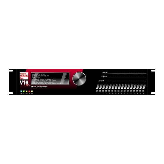
Display The V16Pro includes a standard 8x40 Backlit VFD Display. When the V16Pro is in startup or configuration mode, the display will show setup parameter menus and feedback controlled by the menu wheel. When in the show control mode, the display may be configured to give up to 8 lines of text as needed. -
Page 95: Menu Wheel
Menu Wheel The Menu Wheel provides easy access to all of the configurable parameters of the V16Pro. By rotating the wheel to the right or to left will cause menus will scroll forward or backward. Pressing the menu wheel will select the displayed item. - Page 96 Exit Network Network Adapter A IP Address: 192.168.000.254 Subnet Mask: 255.255.255.000 Gateway: 192.168.000.001 Network Adapter B IP Address: 192.168.000.253 Subnet Mask: 255.255.255.000 Gateway: 192.168.000.001 Exit Password Enter Password Script Configuration Default Script, Reload and View Watches. Exit V16Pro Page 96...
-
Page 97: Function Description
At the end of each menu is the "Exit", this item will pop to the preceding upper level menu. If the menu is at the top the Exit item will exit the menu system and take the V16Pro back to viewing the operation of the script in one is running. -
Page 98: Real-Time Clock
NTP Ethernet Jack: – Selects the port on the back of the unit that is connected to the Internet and directs the V16Pro to search for the server thru that port, A or B. NTP IP Address: – is the Internet IP address of the NTP server. -
Page 99: Ltc/Smpte
(preroll, start and end times), (loop, powerup, restart and idle modes), and output levels. Exit Network There are two independent network controllers in the V16Pro and each of them has separate configuration options as follows Network Adapter A (Defaults) IP Address: 192.168.000.254... -
Page 100: Digital Inputs
Digital Inputs Input Connector The V16Pro has 16 opto-isolated inputs that can control the show operation. If desired, the software may be configured to allow the front panel buttons to mimic these inputs. Otherwise, the front panel buttons operate independently, as an additional set of sixteen inputs. We’ll describe your configuration operation in a couple of pages. -
Page 101: Voltage Inputs Vs. Contact Closures
Two forms of inputs can be applied to the Parallel Inputs connector: Voltage Inputs, and Contact Closures. When a specific input on the V16Pro is software configured for Voltage Inputs, power for the connection is provided by an external source (in-rack power supply etc.), but when the input is configured as a Contact Closure, power is taken... -
Page 102: Input Configuration
Inputs. The window shown below lets you select the input type for each input. Notice the input name may be changed, and a comment describing the input’s use may be added. This makes it easier to remember what you were trying to do when you look at the script again later! V16Pro Page 102... -
Page 103: Input Wiring
(pin 20 for Input1, Pin 21 for Input2, etc.) Figure 3 - Sample connection for a Voltage Input to Input1 of the Parallel Inputs connector. The terminal blocks are used for power bussing and modularization of the input signals. V16Pro Page 103... -
Page 104: Connecting A Contact Closure
Connect the appropriate Input Return pin to the other terminal of the external contact (pin 20 for Input1, Pin 21 for Input2, etc.) Figure 4 - Sample connection for a Contact Closure Input to Input1 of the Parallel Inputs connector. V16Pro Page 104... -
Page 105: Using Front Panel Buttons
Notice the Button name may be changed as well as adding comment to describe the function. The front panel buttons on the V16Pro are not, by default, connected to the associated back panel input with the same number. In fact the front panel buttons are completely independent inputs. -
Page 106: Digital Outputs
Digital Outputs Configuring Outputs The V16Pro provides 16 Dry-Contact Relay Outputs for discrete control. The initial state of each output may be configured by WinScript Live to be open or closed when the script is started. The back panel outputs are configured by WinScript Live software. Select Resources command from the main menu bar then select Outputs. - Page 107 Output 13 Output 13 Return Output 14 Output 14 Return Output 15 Output 15 Return Output 16 Output 16 Return Table 10 – Parallel Output connections. V16Pro Page 107...
-
Page 108: Wiring Outputs
Connect the negative terminal of the device that is receiving the output signal to the negative terminal of the external power supply. Figure 7 – An indicator lamp is a common example of a non-inductive load V16Pro Page 108... -
Page 109: Inductive Loads
Note the polarity of the diode in reference to the supply. Figure 8 - A relay coil or solenoid is a common example of an inductive load and must have a 1N4000-Series snubber diode placed across it. Be sure to observe proper polarity (anode to negative side). V16Pro Page 109... -
Page 110: Video Sync Input
BNC "T" connector may be used to daisy chain the signal. If the V16Pro the only device connected or is the last device in the chain, terminate the line by setting the "75 Ohm" rear-panel dipswitch to "on"... -
Page 111: Rear Dip Switches
(ON) will apply 75Ω termination. Up (OFF) will remove this termination. Terminated No Termination Sync The second switch configures the V16Pro to receive either Blackburst or Composite Sync (C-Sync). Down (ON) will configure for C-Sync. Up (OFF) will configure for Blackburst. C-Sync Blackburst Reset will restore certain settings back to factory defaults. -
Page 112: Firmware
Show Memory When scripts are compiled and sent to the V16Pro, the data is stored in the rear-panel accessible Compact Flash card. The smallest Compact Flash card made will accommodate about a hundred copies of the largest script ever written, so it won’t be necessary to upgrade this memory! Finally something that’s not bigger, costs more or you... -
Page 113: V16+ Or V4+ Compatibility
If you have custom protocols (.pcl files) for your .amw script, you will need to convert them to .prd files using the "Product File Converter" under the "Tools" menu. Then, place the .prd file under the "Alcorn McBride Inc\WinScriptLive\My Product Files" directory under "My Documents" directory. -
Page 115: V4Pro
V4Pro Figure 9- Front View Figure 10 - Rear View Specifications Size and Weight: Standard 2U rack mount (3.5" x 17" x 10.5"), 10 lbs 12 VDC at 3 amps. An external power supply is included Power: with the V4Pro and will provide the required input power. The power supply is rating is 100 to 250 VAC, 50 to 60 Hz, 25-watts maximum. -
Page 116: Certifications
Power barrel jack Ethernet Jack A Ethernet Jack B Serial Ports: RS-232C, RS-422/485, individually software configurable 300 baud – 115.2 Kbaud 7, 8, or 9 Data Bits 1 or 2 Stop Bits All parity types MIDI MIDI input and output ports (16) Each input is software configurable for voltage or Opto Inputs: contact-closure operation. -
Page 117: Serial, Usb, Ethernet, Inputs And Outputs
EN 61000-4-11, Voltage Dips and Variations - Audio Frequency: Annex B Serial, USB, Ethernet, Inputs and Outputs Refer to the V16Pro section for hardware information about serial ports, usb, ethernet and IO. Any information in the V16Pro hardware section regarding SMPTE or Ports 5-16 should be ignored for the V4Pro. -
Page 118: Vcore
VCore Figure 11 - Front View Figure 12 - Rear View VCore Page 118... - Page 119 Figure 13 - Top View Figure 14 - Bottom View VCore Page 119...
-
Page 120: Specifications
Specifications 8” W x 4.75” H x 2” D Size and Weight: (20.32 cm W x 12.07 cm H x 5.08 cm D), 2RU 3 lbs. (1.4 Kg) Power: Power Options: Power-over-Ethernet (POE) capable; or AC Adapter AC Adapter Option: 100 to 250 VAC, 50 to 60 Hz, 20W maximum (CE, UL, CSA, WEEE, RoHS Compliant) Environment: 0 to 38 C (32 to 100 F) -
Page 121: Setting Vcore Ip Address
Setting VCore IP Address The three different ways to set the IP address are listed below. DHCP (Automatic Assignment) Connect to your existing network. Make sure DIP switch position 1 is "ON" The "Network/Config" LED will turn green when a valid IP has been assigned. Manual IP Set Set DIP switch 1 to "OFF"... -
Page 122: Usb Or Serial Set
If your device cannot be reached, try clicking "Send Again." If it still cannot be reached, try a different IP address by starting again with step 2. USB or Serial Set Set DIP switch 1 to "OFF" Open "AMI-Terminal" from the "Tools" menu in WinScriptLive or from start menu. Click on "USB"... -
Page 123: Serial Port
Ethernet see the sections on Ethernet and Networking Primer at the end of this manual. For Cable pin-out, see the Ethernet section of the V16Pro manual. The protocols available on the VCore are currently: Ethernet IP Client (CIP), TCP Client, TCP Server, ModBus TCP, HTTP (Custom web pages), FTP server, DHCP, NTP, and SMTP Client. -
Page 124: Digital Inputs
The DIP switch position 2 determines Contact Closure or Voltage Mode. For the pros and cons of each, see the section titled "Voltage Inputs vs. Contact Closures" in the V16Pro section of this manual. Input Configuration The input names are configured by WinScript Live software. Select Resources command from the main menu bar, and then select Inputs. -
Page 125: Input Wiring
Input Wiring Connecting a Voltage Input Attach the wire from the Input signal pin to the + terminal of the external power supply. Connect the negative terminal of the external power supply to one of the terminals of the contact closure or push button. Connect the appropriate Input Return pin to the other terminal of the contact closure Figure 15 - Sample connection for a Voltage Input to Input1 of the Parallel Inputs connector. -
Page 126: Connecting A Contact Closure
Connecting a Contact Closure Attach the appropriate wire from the Input signal pin (pin 1 for Input1, pin 2 for Input2, etc.) to one of the terminals of the external contact. Connect the appropriate Input Return pin to the other terminal of the external contact closest to the word "inputs"... -
Page 127: Digital Outputs
Digital Outputs Configuring Outputs The VCore provides 4 Dry-Contact Relay Outputs for discrete control. The initial state of each output may be configured by WinScript Live to be open or closed when the script is started. The back panel outputs are configured by WinScript Live software. Select Resources command from the main menu bar then select Outputs. -
Page 128: Wiring Outputs
Wiring Outputs Non-inductive load Non-inductive loads are resistive. Incandescent bulbs, LEDs and filament lamps do not require additional hardware. Loads that do not have inductors, coils or transformers are non-inductive loads. Attach the appropriate Output pin (pin 1 for Output1, pin 2 for Output2, etc.) on the Parallel Outputs connector to the positive terminal of the external power supply. -
Page 129: Inductive Loads
Inductive loads Inductive loads have inductors, coils or transformers as part of the load or may be the load. Relays, motors and mechanical actuators such as door latches, curtain controllers and other such devices are all inductive loads. These devices store electromagnetic energy to do work. -
Page 130: Led Indicators
LED Indicators Script/Comm - usually solid green, frequently solid yellow Connection No script is loaded, Script failed to load Solid Green Script is loaded and running Fast Blinking Red SD card for script removed or not detected Red Single Blink Invalid Communication from device or Solid Red or no response from device... -
Page 131: Power Supply
Power Supply The VCore includes an external universal power supply that allows connection too many domestic as well as international wall voltages (110VAC, 220VAC, 200VAC) without special configuration. The VCore uses a 2-position terminal block plug (3.5mm spacing) as its power input. -
Page 132: Show Memory
Closure Reset Will restore certain settings back to factory defaults. These settings include: IP Address, Date/Time and related time zone configuration, NTP, SMTP, E-mail Settings, and Script Variables stored using "Save Variable." To apply the reset, flip the switch up into the "OFF" position. Leave in this position for about 1 minute. -
Page 133: Scheduler (Web-Based)
The example that follows will use the V16Pro and will apply equally well to the entire show controller family. Getting Started Using a web browser, enter the IP address of the V16Pro into the address bar. The admin user must be logged-in to edit schedule files. Enter the admin user name and password then click “Login”. - Page 134 Enter the name of the schedule and click “Create” Select the schedule file to edit and click “Edit” New schedule files have no entries. Click “New Line” to create a new entry in the schedule. Scheduler (Web-based) Page 134...
-
Page 135: Editing Schedule Entries
Editing Schedule Entries Click “Edit” to change the new entry created. The entry is empty when it is first created. Enter the following information to complete entry: Sequence: The name of the sequence to start Start time: The time from 00:00 to 23:59 to start the selected sequence Repeat Period: Select whether the entry should repeat, and how often... - Page 136 In this example, the sequence “Turn On All Outputs” will start at 7:30am every day starting on April 21 , 2009. Click “Save” to save changes to the entry. The list now shows the entry that starts the sequence “Turn On All Outputs” and another entry that was created to turn off all outputs every day at 4:30pm (16:30).
- Page 137 Select the schedule to use and click “Set Active”. The active schedule will always be shown on this page. Scheduler (Web-based) Page 137...
-
Page 139: Web Server Quick Start
WEB Server Quick Start This quick start will demonstrate how to connect to the web server from your computer, use the configuration web pages provided, and walk-through how to setup a web page for your customer. This quick start assumes that theV16Pro is used and is configured using factory settings and the original Compact Flash card provided. -
Page 140: Step 2: Configuration
Step 2: Configuration Select the "Web Server" link to display web server settings. The following screen shot shows this page. Set the customer login name to "customer" or another name of your choice. Set the customer password. Leave the other settings as they are and click "Apply". These changes will occur immediately and there is no restart required. -
Page 141: Step 4: Understanding Home.php
This page demonstrates how to start sequences, turn on and off outputs, and set the value of variables in the currently running show. You can modify this page to make an easy to use interface for the customer. To modify this page, the file "home.php"... -
Page 142: Hypertext Transfer Protocol
Hypertext Transfer Protocol The show controller’s have a built-in HTTP server for serving web pages to remote web clients. By default, the server is available on both Ethernet ports using TCP port 80. The server can be disabled from one or both ports to prevent unauthorized access to this service (see the section on Web Server Configuration). -
Page 143: Show Controller Web-Script
Show Controller Web-Script The show controller’s HTTP server supports a scripting language with a similar syntax to the widely used PHP language. This syntax is recognized by many modern HTML editors and therefore will not interfere with the design of a web page. Although the syntax is similar, the show controllers do not support the PHP language. -
Page 144: Variables
Variables There are three global variables: $_POST, $_ENV, and $_SERVER. These variables are used in a similar way to their PHP counterparts. The show controller web-script does not support local variables and does not allow the value of a variable to be changed directly (see the section on Functions). - Page 145 The state of the NTP client "checked" = disabled "" = enabled Versions v16sn The serial number of this V16Pro v16ver The firmware version of this V16Pro smptever The firmware version of the SMPTE module in this V16Pro Date/Time date The current date in the form "m/d/Y"...
-
Page 146: Functions
$_SERVER index name Description example: <V16Pro> "email@address.com" HTTP httpa The state of the HTTP server for port A "checked" = enabled "" = disabled httpb The state of the HTTP server for port B "checked" = enabled "" = disabled... - Page 147 Name Params Description works if no data has been sent. Access requirelogin 1. Minimum user level that Use this function before is required to view the page any data is sent to ensure the user has the proper access level. See $_SERVER["level"] for access level values and their meanings.
- Page 148 Name Params Description page to load when no page is specified by a request setcustauth 1. The customer user name Set the customer user 2. The customer password name and password for the HTTP server login Date/Time Settings settime 1. The time. Set the current time See $_SERVER["time"] for formatting.
-
Page 149: Function Params
Function Params A function parameter can be a string, number, variable, or combination thereof. following table defines these parameter types Type Usage String A string is any combination of double-quoted values and hex values. Double-quoted values may include escape characters using a backslash \ Valid escape characters are: \r –... -
Page 150: Web Server Configuration
Web Server Configuration The web server can be enabled or disabled on any of the Ethernet ports. Follow the Quick Start section to login to the administrator web pages and display the Web Server Settings as shown: Ethernet Jack(s) – use these checkboxes to enable or disable the web server on the specified ports. -
Page 151: Serial And Ethernet Control
Live Mode command when told to monitor a variable. Get Firmware Version Description: This command will return the controller firmware version number. Command: ?V<0D> Message Response: V16Pro Vx.xx<0D> Example: Send Command: ?V<0D> Response: V16Pro V1.23<0D> Get SMPTE Firmware Version Description: This command will return the firmware version of the SMPTE module. -
Page 152: Es Enable Smpte
Enable SMPTE Description: This command will enable SMPTE module. Comments: If the SMPTE module is configured to Generate, this command will cause the clock to start generating at the configured Preroll time. If the SMPTE module is configured to Read, it will start listening for SMPTE time code on the SMPTE Input. -
Page 153: Is Pause Smpte (Immediately)
Pause SMPTE (Immediately) Description: This command will pause the SMPTE clock immediately. Comments: When paused, the SMPTE clock can be resumed by sending an Enable SMPTE command. Get command: IS<0D> Message Response: R<0D> Example: Send Command: IS<0D> Response: R<0D> Get/Set SMPTE Time Description: This command will get or set the current SMPTE time. -
Page 154: Ip Get/Set Ip Address
Example: Send Command: 1ID<0D> Response: R<0D> Get/Set IP address Description: This command will get or set the selected port IP address. Port A or B may be selected Where xxx is a decimal number in the range of 0 – 255. Comments: Get command: (A or B)IP<0D>... -
Page 155: Da Get/Set Date
Example: Send Command: GW<0D> Response: 192.168.0.1<0D> Set command: xxx.xxx.xxx.xxxGW<0D> Message Response: R<0D> Example: Send Command: 192.168.0.1GW<0D> Response: R<0D> Get/Set Date Description: This command will get or set the calendar date. Comments: mm/dd/yyyy Month/Day/Year. Get command: DA<0D> Message Response: mm/dd/yyyy<0D> Example: Send Command: DA<0D>... -
Page 156: Us Get/Set User Name
Get/Set User Name Description: This command will get or set the user login name. Comments: The default name is admin. Get command: US<0D> Message Response: (current login)<0D> Example: Send Command: US<0D> Response: admin<0D> Set command: (new login)US<0D> Message Response: R<0D> Example: Send Command: adminUS<0D>... -
Page 157: Dt Get/Set Dst Type
Example: Send Command: 1SD<0D> Response: R<0D> Get/Set DST Type Description: This command will get or set the status of the daylight saving time Type. Comments: Example are: 1 = US, 2 = Universal, 3 = Australia, 4 = Europe. Get command: DT<0D>... -
Page 158: Lo Get/Set Longitude Coordinates
Message Response: R<0D> Example: Send Command: "Display Text"|4|10DI<0D> Response: R<0D> Get/Set Longitude Coordinates Description: This command will get or set the longitude coordinates. Get command: LO<0D> Message Response: current value<0D> Example: Send Command: LO<0D> Response: 81.0<0D> Set command: 81.0LO<0D> Message Response: R<0D>... -
Page 159: Vt Toggle A Boolean Variable
Example: Send Command: var1|"Hello World"VA<0D> Response: R<0D> Toggle a Boolean Variable Description: This command will change the variable state to the opposite state Comments: 0 to 1, 1 to 0, Off to On, On to Off. Command: var1VT<0D> Message Response: R<0D>... -
Page 160: Pl Run A Sequence
Example: Send Command: mySeqSL<0D> Response: R<0D> Run a Sequence Description: This command will run a sequence from the currently selected script. The sequence is identified by its number. Comments: The sequence number is the first field in the form. WinScript Live assigns the number. -
Page 161: Reboot
Example: Send Command: Sport1|"Hello World"SS<0D> Response: R<0D> Reboot Description: This command will perform a hard reboot of the system. Comments: The show controller will reload and run the selected script. The normal power on response will apply Command: XX<0D> Message Response: K<0D>... -
Page 162: Nj Get/Set The Ethernet Port For Ntp
Message Response: R<0D> Example: Send Command: 1NE<0D> Response: R<0D> Get/Set the Ethernet Port for NTP Description: This command will get or set the show controller Ethernet port used to contact the NTP server. Comments: A = port A, B = port B. The default port is A Get command: NJ<0D>... -
Page 163: Nm Get/Set Device Name
Description: This command will get the current device name or set the name of the device. Comments: This can be used to "Name" your V16Pro for reference when you're looking at the device list in Live Mode. Get command: NM<0D>... -
Page 164: Sj Get/Set The Ethernet Port For Smtp
Get command: pDH<0D> Message Response: x<0D> Example: Send Command: ADH<0D> (returns port A status) Response: 1<0D> Set command: xpDH<0D> Message Response: R<0D> Example: Send Command: 1ADH<0D> (enables port A) Response: R<0D> Get/Set the Ethernet Port for SMTP Description: This command will get or set the show controller Ethernet port used to contact the SMTP server. -
Page 165: Sp Get/Set The Smtp Port
Get/Set the SMTP Port Description: This command will get or set the SMTP port number needed to contact the SMTP server. Comments: 0 to 65535. The default port number is 578 Get command: SP<0D> Message Response: (current port)<0D> Example: Send Command:SP<0D> Response: A<0D>... -
Page 166: Fr Get/Set The Smtp From Name
Message Response: R<0D> Example: Send Command: NewPasswordSW<0D> Response: R<0D> Get/Set the SMTP From Name Description: This command will get or set the SMTP name used in the from-field of the E- Mail. Comments: A text string such as mylogin Get command: FR<0D>... - Page 167 Example: Send Command: AHJ<0D> (enables port A) Response: R<0D> Serial and Ethernet Control Page 167...
-
Page 168: Hp Get/Set The Http Web Page
Get/Set the HTTP WEB Page Description: This command will get or set the default HTTP WEB address. Comments: The default WEB page is index.html Get command: HP<0D> Message Response: (currentwebpage)<0D> Example: Send Command: HP<0D> Response: myWebPage.html<0D> Set command: (myWebPage.html)HP<0D> Message Response: R<0D>... -
Page 169: Ms Get/Set Master Slave Message
Example: Send Command: ARX<0D> Response: R<0D> Get/Set Master Slave Message Description: This command will get or set the Master Slave Message. “1” represents force to slave, “2” represents force to master, and “0” represents Comments: force to be stand alone (disabled). Get command: MS<0D>... -
Page 170: Lv Live Mode
Set command: (nnn)TMS <0D> Message Response: R<0D> Example: Description: Jump sequence "MySequence" to timecode 00:00:01.00 Send Command: MySequence|00:00:01.00JP<0D> Response: R<0D> Live Mode Description: This command is the Live mode initiator. The live mode starts a real time interface between the host system and the show controller. Information is requested by the following protocol. - Page 171 If WinScript Live is not used as the script editor, there is a way to speed up the interpretation of the data fields needed to execute the sequence commands. The above command line is written as: V16Pro|On|output1[8]EX<0D> [x] points the show controller to use the parallel output1 instead of something else called by the same label.
-
Page 173: Product File Creator
Product File Creator The "Product File Creator" tool found under the "Tools" menu of WinScriptLive can be used to get started creating a product file. This can be used for adding new product files to WinScriptLive. The following tutorial is only in reference to creating a product file through the use of this tool built into WinScriptLive. -
Page 174: Live Mode Protocol
Live Mode Protocol Live Mode communication is used by the show controllers to give updated information on the state of variables, inputs, outputs and other resources. This information is not polled, but instead requested once and then the show controller will send updated information as that resource changes. This method is used by Touch to retrieve status information and can also be used by third party drivers. -
Page 175: Resource Requests
s - the ASCII letter 's' <index of sequence> - the zero indexed number of the sequence in the "sequences" view of WinScriptLive <sequence state> - The sequence running state: Stopped =0, Running = 1, Paused = 2 <frames> - The sequence's current time (in frames) <event1>..<eventN>... -
Page 176: Resource Status
Watch Sequence #100 (To get frame counter and events recently executed) Command: s|1|99|-1|-1LV Message Ack Response: R Watch V16Pro's integer variable V16Pro.Hours (variable #12 in V16pro's "Device Variables" list) Command: v|1|11|0|-1LV Message Ack Response: R Watch V16Pro's Timecode variable V16Pro.LTC (variable #1 in V16pro's "Device Variables" list) -
Page 177: Resource Status Examples
Resource Status Examples V16Pro's LTC Timecode Variable #1 is 00:00:00.02: v|0|0|00:00:00.02|-1LV Device #8 variable number #100 is 1234 v|99|7|1234|-1LV User variable number #100, list (array) position 8 is 456 v|99|-1|456|7LV Input #5 status is "Off" i|4|-1|0LV Input #5 status is "On"... -
Page 178: User Log Message
User Log Message Error status is returned in the following format: <type>|<level>|<message>LV • <type> = single ascii character the item type (see Resource Type Table) • <level> = "information", "warning" or "error (see Log Type Table) • <message> = the actual message information Log Type Information Warning... -
Page 179: Troubleshooting Tips
Troubleshooting Tips The following table provides some possible reasons for behavior of the show controller or WinScriptLive. Please see our website for more frequently asked questions and knowledgebase. WinScriptLive Symptom Possible Cause Possible Solution Can’t send a script – Compact Flash card failure Remove compact flash card from WinScriptLive stays stuck on rear of unit.
Need help?
Do you have a question about the V16Pro and is the answer not in the manual?
Questions and answers