Table of Contents
Advertisement
Operation Manual
Multi-Function Professional Robotic Controller
This document contains information is proprietary of KXWELL INTERNATIONAL PTE LTD; it's intended for the specific use of the
recipient for the express purpose of evaluating and operating off KXWELL products. This document is provided with the expressed
understanding that the recipient will not divulge to other parties or otherwise misappropriate the information contained herein.
© 2016 KXWELL INTERNATIONAL PTE LTD. All rights reserved. All information is subject to change without prior notice.
KT-RP8810U-J2
Version 201707 1.1
Advertisement
Table of Contents

Summary of Contents for KXWELL KT-RP8810U-J2
- Page 1 Version 201707 1.1 This document contains information is proprietary of KXWELL INTERNATIONAL PTE LTD; it’s intended for the specific use of the recipient for the express purpose of evaluating and operating off KXWELL products. This document is provided with the expressed understanding that the recipient will not divulge to other parties or otherwise misappropriate the information contained herein.
- Page 2 Please read this operation manual before set-up and operate the robotic system. KXWELL will not responsible for any misuse and miss-operate of KXWLL products. WARNING! This product must be used within the specified instruction and connection...
- Page 3 Safety Precautions This section is to guide users to use this product correctly, thus to prevent danger or property damage. Please read this manual carefully before using the product and keep it properly for future reference. WARNING: Alerts user CAUTION: Alerts user of a potential potential hazard which, if not avoided, hazard which, if not avoided, could could result in serious injury or death...
-
Page 4: Table Of Contents
CONTENTS PRODUCT FEATURES ................- 1 - INSTRUCTIONS FOR CONTROLLER INSTALLATION AND USE ..- 2 - ..................- 3 - OWER ON ........- 4 - TILT EAD AND AMERA TERCONNECTION INSTRUCTIONS FOR SYSTEM CONNECTION ........- 5 - RS422 L ................ - Page 5 ........- 20 - OW TO WITCH THE AMERA OCUS ..... - 21 - OW TO EMOTELY ONTROL AMERA OWER ......... - 21 - OW TO ISPLAY AMERA MAGE HARACTERS ........- 22 - OW TO DJUST AMERA MAGE ARAMETERS 5.5.1 Setting White Balance Mode ...........
- Page 6 5.19 GPI F ............- 42 - OW TO SE THE UNCTION 5.20 ..........- 43 - OW TO ESET TO ACTORY ETTINGS 5.21 ..........- 44 - OW TO ERSION NFORMATION 5.22 ............. - 44 - OW TO ERVICES DESCRIPTION OF ABNORMAL STATES ..........
-
Page 7: Product Features
Automatic detect and recognize of camera model when connected, while selecting different camera for operation Support and control KXWELL video selector or provide GPI to trigger 3 party router /switcher control panel to preview the camera video while operation. -
Page 8: Instructions For Controller Installation And Use
2 Instructions for Controller Installation and Use Please following below procedure before using the device: Read manual carefully and practice to get familiar with the functional and operations of the controller; Carry out the wiring connection according to the system connection diagram Power on system devices at each level;... -
Page 9: Power On
[1] in the functional zone of preset position buttons remain on. CAUTION To ensure that the controller was supplied with proper voltage; user are advise to use the standard power adapter supplied by KXWELL. - 3 -... -
Page 10: Pan/Tilt Head And Camera Interconnection
Pan/tilt Head and Camera Interconnection Cable connection: Connect to the correct interface “RS422/ IP” for both control panel and robotic head as below: Connect to port on the controller if the link mode is RS422 and to port if the TCP/IP interface is use. Can configure mix “RS422/ IP” control interface for each robotic camera in the same controller. -
Page 11: Instructions For System Connection
3 Instructions for System Connection RS422 Link Mode - 5 -... -
Page 12: Network Connection Node
Network Connection - 6 -... -
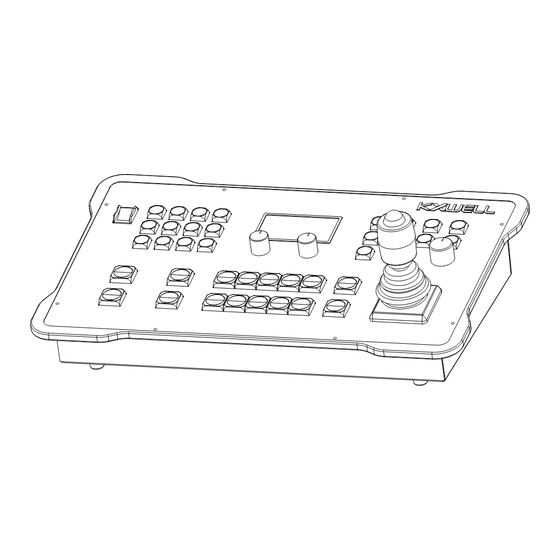
Page 13: Description Of Controller Functions
4 Description of Controller Functions Functions of Controller Panel Power ON / OFF switch Robotic Head / Camera selection buttons LCD Display and knobs F1 and F2 Parameter setup buttons Iris control Robotic joystick control Preset & Pan / Tilt limit setup buttons Zoom and Focus buttons - 7 -... -
Page 14: Operate Switch
Camera power ON and OFF can be achieved if the camera is draw DC power from pan/tilt head. Supply power to KXWELL robotic head, will not directly supply the DC to the camera until power ON the controller or select the particular robotic button on the controller is the controller was ON. -
Page 15: Display Screen And Knobs F1 And F2
4.3 Display Screen and Knobs F1 and F2 The LCD display screen is used to display operation info MAIN MENU and status; knobs are used to adjust the parameters selected and set-up of the Camera, Robotic Head, Control Panel. Knob F1 & F2 are use to adjust the speed control of Joystick including the Zoom and Focus Button operation speed. - Page 16 Party protocols, operating modes. Table 1, 2 and 3 define the functions of the buttons in F1, F2 and F3 “PAGE” for the KXWELL protocol. Table 4 and 5 define the functions of buttons in F1 and F2 “PAGE” for the VISCA protocol.
- Page 17 Table 2. Functions of parameter setup buttons for the KXWELL protocol in F2 PAGE Function Description of function of button F2 PAGE, the indicator light of this button remains on and builds in NO function. CAM. Launch the Quick Camera Parameter Setup (camera dependent) on P.T.
-
Page 18: Iris Control Zone
Table 5. Functions of parameter setup buttons for the VISCA protocol in F2 PAGE Function Description of function of button CON. Open the Controller Parameter Setup menu 4.5 Iris Control Zone IRIS AUTO MANU Press the [IRIS] button to switch the iris to AUTO, MANNUAL and LOCK LOCK mode. - Page 19 OFF-LOCK ORG-ZOOM The button and the button on the top of joystick are use to switch the RED-FOCUS dial function at the upper part of joystick for ZOOM or FOCUS operation. The indicator light of turns YELLOW if the dial on the joystick as ZOOM operation. TILT “DIAL”...
-
Page 20: Preset Position /Limit Setup Buttons
4.7 Preset Position / Limit Setup Buttons The PRESET / LIMIT buttons use to store PRESET/LIMIT or call the preset positions of pan/tilt head; and set the limit of PAN & TILT head. Select [10+] button to switch from preset MEMO position [1]-[10] to [11]-[20]. -
Page 21: Pan/Tilt Head Parameter Setup Menu
CAUTION The status indicated show on the controller and camera may be different. For such case, the status indicate in camera shall prevail. Pan/Tilt Head Parameter Setup Menu To setup the Pan/Tilt Head Parameter: Press the [PAGE] button and light turns yellow, press the [P.T.] button to enter Pan Tilt setup;... -
Page 22: Camera Parameter Setup Menu
YES!; NO! Save parameters to current SAVE selected pan/tilt head 4.10 Camera Parameter Setup Menu The Camera Parameter Setup menu allows setup of camera parameters. Press the [PAGE] button and light turns yellow, press the [CAM.] button to enter camera parameter setup; the screen will display the Camera Parameter Setup menu according to the connected camera type. - Page 23 CLR; ND1; ND2; ND3 Set the camera ND filter MANU; AUTO Set the gain mode GAIN MODE 01dB~40dB Adjust the gain value (Changeable when GAIN SET the gain mode is in MANU) OFF; 6dB; 12dB; 18dB; Adjust the gain limit (Changeable when AGC MAX 24dB the gain mode is in AUTO)
-
Page 24: Controller Parameter Setup Menu
Set the „IRIS” adjustment direction with iris in I.DIR NORMAL; REVERSE manual mode. TCP; RS422 Set the link mode for system control LINK MODE PROTOCOL KXWELL; VISCA Set the communication protocol for to controller GPI SET ENABLE; Set the GPI DISABLE - 18 -... - Page 25 SYS.INFO View device info SAVE YES!; NO! Save current settings of controller CAUTION Changes of [P.DIR], [T.DIR], [Z.DIR], [F.DIR] and [I.DIR] will take effect immediately, while changes of [LINK MODE] and [PROTOCOL] will take effect only after [SAVE] was executed. - 19 -...
-
Page 26: Controller User Guide
5 Controller User Guide How to Adjust the Iris When the light of [IRIS] button is OFF “no light”, the camera IRIS AUTO in AUTO iris mode. MANU Press the [IRIS] button and show yellow light, the camera in LOCK MANUAL iris mode. -
Page 27: How To Remotely Control Camera Power On/Off
10 second to detect camera and lens installed. CAUTION When the KXWELL protocol is used for communication, after executing the camera shutdown command, the camera will be disconnected from the controller and lose control. User can select this camera again to restore control over the camera. -
Page 28: How To Adjust Camera Image Parameters
turns yellow, the OSD is on; when the indicator light of [OSD|MEMO] goes off, the OSD is off. OSD = ON SCREEN DIPLAY. NOTE Do not on the OSD if taking video direct from the camera to ONAIR. How to Adjust Camera Image Parameters The controller integrated of camera image parameters control menu such as white balance, shutter, filter and gain. -
Page 29: Change And Select Nd Filters
Select [RET|WB1] button to switch the white balance/ 3200K color temperature mode of camera. Select [U3|WB2] button to switch the white balance/ 5600K color temperature mode of camera. Select [OSD|MEMO] button to switch the white balance/ MEMO mode of camera. CAUTION ... -
Page 30: Setting Gain
Parameter Setup menu. to move the pointer to select “shutter speed”; rotate 3. Rotate knob knob to change the shutter speed. 5.5.4 Setting Gain Set the gain mode →GAIN MODE:MANU 1. Select F2 [PAGE] button to light up in yellow. 2. -
Page 31: Switching Between Video Output Or Color Bar Output
Set manual gain →GAIN SET: 01dB 1. Select F2 [PAGE] button to light up in yellow. 2. Select the [CAM.] button and the LCD display will show the Camera Parameter Setup menu. to move the pointer to select “Gain Set”; rotate knob 3. -
Page 32: Setting Master Black Level
Parameter Setup menu. to move the pointer to select “R.GAIN”; rotate knob 3. Rotate knob to change the RED gain. to move the pointer to select “B.GAIN”; rotate knob 4. Rotate knob to change the BLUE gain. 5.5.7 Setting Master Black Level Operation steps: →M.BLACK:... -
Page 33: How To Start And Stop Camera Recording
to move the pointer to select “DTL”; rotate knob Rotate knob to adjust the detail level of camera. How to Start and Stop Camera Recording REC|ATW Operation steps: [PAGE] button at F1, [PAGE] button indicator light is OFF. Press the [REC|ATW] button to turn on its yellow light; the camera will start recording. -
Page 34: How To Store And Recall Preset Positions
Press [ENTER] button to execute the selected menu to change the setting or enter to the submenu of the camera. Press [↑] [↓] to change the value. Some cameras have [MENU2]; when the [MENU2] button is pressed, the monitor will display a special camera menu. NOTE ... -
Page 35: How To Set Pan/Tilt Limit Position
KT-RP8810 is able to save up till 20 preset memory per robotic head. KT-RP8810 preset memory will overwrite the preset memory if the preset is being saved in the same ID location. KXWELL Preset memory will saved in Robotic Head. How to set Pan/Tilt Limit Position PRESET/LIMIT... -
Page 36: How To Switch Tracking Mode
TRC.A/ M [TRC.A/M] button use for enable and disable 3 party manufacturer auto tracking devise to control KXWELL robotic head in one system. Operation steps: [PAGE] button at F1, [PAGE] button indicator light is OFF. [TRC.A/M] button the indicator light is OFF; allow 3 party manufacturer auto tracking devise to control KXWELL robotic head. -
Page 37: How To Configure The Movement Direction Of Pan /Tilt Head
5.12 How to Configure the Movement Direction of Pan/Tilt Head Operation steps for setting reverse movement direction of pan/tilt head: Press the [PAGE] button and yellow light ON. Press the [P.T] button and yellow light ON; the LCD display will show the Pan/Tilt Head Parameter Setup menu. - Page 38 refer to the detailed descriptions of these items in Table 8 in “Page 18”. In the Controller Parameter Setup menu, rotate knob to move the pointer to select “SAVE”; rotate knob to select “YES!”; press change and show “DONE”, this will apply the movement setting of pan/tilt head. CAUTION ...
-
Page 39: How To Link Pan/Tilt Head Control With Lens Zoom
5.14 How to Link Pan/Tilt Head Control with Lens Zoom Automatically slow down the maximum speed of Pan and Tilt while lens in ZOOM IN position if this function is ON. Operation steps: Press [PAGE] button and yellow light ON. ... -
Page 40: How To Configure The Link Mode
5.15 How to Configure the Link Mode Set Controller to RS422 or IP link interface depend on the configuration. Operation steps: Determine the link mode for pan/tilt head by the method described in the Instruction Manual for Pan/Tilt Head. Both controller and robotic head nee to have same control interface. -
Page 41: How To Lock The Controller
5.16 How to Lock the Controller Operation steps for locking the keyboard in the zone of camera selection buttons: Indicator light for [LOCK] button is OFF at normal circumstances. Press and hold the [LOCK] button for 2s, the indicator light of [LOCK] will turn green. -
Page 42: How To Configure The Communication Protocol
Controller Parameter Setup menu. Rotate knob to move the pointer to select [PROTOCOL]; rotate to select “KXWELL” or “VISCA”, thus to match it with the communication protocol of pan/tilt head. Rotate knob to move the pointer to select [SAVE]; rotate knob change it to “YES!”;... - Page 43 apply the communication protocol setting. CAUTION Able to set different communication protocol for each robotic. In case of no communication between controller and robotic head, directly press to enter the Controller Parameter Setup menu, where the communication protocol can be configured as steps 5.17 to get proper connection.
-
Page 44: How To Configure Network Ip For The Controller
5.18 How to Configure Network IP for the Controller Open the Network Configuration interface: Press the [PAGE] button and the yellow light ON. Press the [CON.] button and yellow light ON; the LCD display will show the Controller Parameter Setup menu. - Page 45 change the numerical of SUB-MASK address field. After setup, press return to the Network Parameter Setup menu. Configure the default gateway of controller In the Network Parameter Setup menu, rotate knob to move the pointer to select [GATEWAY], and press to enter gateway address setup with cursor shown.
- Page 46 Parameter Setup menu. Configure the port of pan/tilt head: Determine the port number of pan/tilt head by the method described in the Instruction Manual for Pan/Tilt Head. In the Network Parameter Setup menu, rotate knob to move the pointer to select [REM.PORT];...
- Page 47 Table 6. Description of configurations in the Controller Network Setup menu Menu item Options Description LOCAL IP 0.0.0.0~255.255.255.255 Controller IP address 0.0.0.0~255.255.255.255 Subnet mask of controller SUB-MASK 0.0.0.0~255.255.255.255 Gateway address of GATEWAY controller REM.PORT 1~65535 Port number of target pan/tilt head REMOTE IP 0.0.0.0~255.255.255.255 IP address of target pan/tilt...
-
Page 48: How To Use The Gpi Function
5.19 How to Use the GPI Function Operation steps for enabling GPI signal: Press the [PAGE] button to turn yellow light ON. Then press the [CON.] button and yellow light ON; the LCD display will show the Controller Parameter Setup menu. -
Page 49: How To Reset To Factory Settings
CAUTION GPI is OFF by default. Any two GPI signals cannot be simultaneously set as the same master monitoring signal. To map [GPI9] to [PGM1] when [PGM1] has been mapped by [GPI2] signal, user can first un-map [GPI2], and then set to map [GPI9] to [PGM1]. 5.20 How to Reset to Factory Settings Operation steps for resetting to factory settings: ... -
Page 50: How To View Version Information
5.21 How to View Version Information Operation steps: Press the [PAGE] button to turn yellow light ON. Then press the [CON.] button and yellow light ON; the LCD display will show the Controller Parameter Setup menu. Rotate knob to move the pointer to select [SYS.INFO], and press ;... - Page 51 Open the Web browser on the computer; enter the controller‟s IP address in the address bar; then press ENTER. - 45 -...
-
Page 52: Description Of Abnormal States
6 Description of Abnormal States Failed of controller may result by poor wire or configuration issue. If the controller is abnormal, there will be an error message and status of the control system show on LCD display with blinking light indicator for corresponding button on the controller. -
Page 53: Network Ip Cable Disconnection State
Network IP Cable Disconnection State When port on the controller is not connected to the router or other IP network device via RJ45 cable, the controller LCD display will show under “NOTE” is “TCP/IP OFF”. This message will be shown only while in TCP/IP link mode configuration. - Page 54 other relevant configuration. If normal communication has been achieved between the controller and the camera or pan/tilt head, “NORMAL-TCP” will be displayed on the third line of the LCD display. - 48 -...
-
Page 55: Port Definition
7 Port Definition Fig. 1 shows the ports of the controller. POWER CON. OUT GPI OUT GPI IN TCP/IP RS 422 REMOTE 1 CAMERA 1-10 REMOTE 2 CAMERA 1-10 GN D SERVICE + 12 V Fig. 1. Ports on the rear panel CAUTION ... -
Page 56: Tcp/Ip Control Port
TCP/IP Control Port Pin No. Pin Definition 4, 5, 7, 8 RS422 Control Port Pin No. Pin Definition 1, 2, 7 - 50 -... -
Page 57: Auxiliary Control Port
Video Selector Control Port The REMOTE2 RS-232 port is use to control KXWELL video selector to trigger and select the camera video for operation preview usage. The selection of the video input will correspondent to the camera selection by KXWELL robotic controller. -
Page 58: External Control Signal Output Port
External Control Signal Output Port GPI OUT 1 to GPI OUT 10 are output GPI interface for controller to interface with party devices. Example: Outputs the GPI to trigger router / AUX control panel with GPI in to fulfill video switching for operation preview. GPI OUT 连接示例... - Page 59 - 53 -...
-
Page 60: External Control Signal Input Port
External Control Signal Input Port GPI IN 1 to GPI IN 10 are use to connect external control signals to KXWELL controller. For example, the Tally GPI from the video switcher. GPI IN 连接示例 GPI IN Circuit GPI IN KX-RP8810U CAMERA 1-10 +3.3 V... -
Page 61: Specification Table
8 Specification Table Item Parameter Type of pan/tilt head KXWELL series robotic heads or 3 party brand*1 supported Control of pan/tilt head and Variable speed control of robotic head and lens; iris and lens focus mode switching*2 Maximum control capacity... -
Page 62: Troubleshooting
9 Troubleshooting Symptom May Cause Solution No power when 1. Controller needs 1. Check there is DC adapter for the switch on the +12V, 3A DC power controller; controller. supply. 2. Confirm the AC supply working properly; 3. Change the AC socket supply to reconfirm. - Page 63 you in house network needs. 3. Pan/tilt heads and cameras can be control normally when the LCD display show at [NOTE] on the third line in the main interface of controller is displayed as NORMAL-TCP. Refer to Section 4.11 on Page - 18 - and Section 5.18 on Page - 38 -.
- Page 64 KXWELL International Pte Ltd. Website: http://www.kxwell.com Official WeChat Account: KXWELL The design and specification of the product is subject to change without notice Printed in China H5BG715...
Need help?
Do you have a question about the KT-RP8810U-J2 and is the answer not in the manual?
Questions and answers