Table of Contents
Advertisement
Quick Links
- 1 Tvu Transceiver and Receiver Components
- 2 Tvu Transceiver Tx3200 Features and Indicators
- 3 Tvu Transceiver Tx3200 Back Panel Connections (Standard Sdi Version)
- 4 Tvu Receiver: Network and Firewall Configuration
- 5 Accessing the Webr
- 6 Appendix C: Tvu Receiver Tr3700
- 7 Appendix E: Tvu Transceiver Tx3250
- Download this manual
Advertisement
Table of Contents

Summary of Contents for TVU networks TR3700
- Page 1 TVU Transceivers & Receivers Set Up and Operating Guide Version 5.5 857 Maude Avenue, Mountain View, CA 94043 Telephone: (650) 969-6732 • FAX: (650) 969-6747 www.tvunetworks.com Printed in U.S.A. ©2016 TVU networks Corporation...
- Page 2 Notices Copyright © 2016 TVU networks Corporation. All Rights Reserved. Photographs are the copyright of their respective owners. Contact TVU networks Corporation at our Web site: www.tvunetworks.com Trademark Notices TVU networks Corporation Trademark Information The following are trademarks of TVU networks Corporation and/or its affiliates in the United States and/or other countries: TVU®, TVU Networks® and TVUPack Other Trademark Information The following are trademarks of their respective owners or companies: TRADEMARK OR REGISTERED TRADEMARK COMPANY Verizon® Verizon Communications, Inc. AT&T® AT&T, Inc. Huawei® Huawei Technologies Co. Ltd. Velcro® Velcro Industries, B.V. FCC/CE Compliance Federal Communications Commission (FCC) Regulation of ENG Mobile Systems The FCC provides specific policies and procedures related to radio frequency (RF) emissions in mobile and portable devices. The FCC outlines test requirements and specific test procedures based on the type of device. These test requirements and procedures can also cover Specific Absorption Rates (SAR) for RF. The TVUPack device has always conformed to all applicable FCC regulations covering mobile systems for electronic newsgathering. All required tests for the TVUPack device as outlined in the regulations were performed by a third party testing lab, which issued a certificate of compliance for the TVUPack. The certificate is applicable to both the FCC and CE. Additionally, the data modems used in TVUPack are commercially available off-the-shelf brands and have been FCC and carrier certified. Supporting documentation demonstrating TVUPack's compliance with the applicable FCC regulations is available upon request. Please contact us at +1.650.969.6732 for assistance and questions regarding approved modem cards for use with TVUPack.
-
Page 3: Table Of Contents
TVU Test Pattern ....................... 30 Accessing the WebR ......................30 TVU Social ......................... 31 TVU Social Media Manager Service (Optional) ..............33 Using the IFB Feature (Optional) ..................35 IS+ (Optional) ........................36 Contacting TVU Networks ..................38 TVU Transceiver TX3200 Technical Specifications ............39 Appendix A: Troubleshooting Video Quality .............. 39 Troubleshooting Video Quality Using the Status Indicators in Normal & Advanced Modes 39 Quality ..........................39 Error rate indicators ......................39 Line quality indicators ......................40 Appendix B: Vislink Hybrid IP Microwave Integration Technology ......41 General Safety Information ....................42 Vislink RF Transport Overview ..................... 43 LGR/TVUPack System Set-Up ....................44 Configuration Steps to Stream Video ................... 45 Appendix C: TVU Receiver TR3700 ................46 Appendix D: TVU Receiver TR3750 ................48 Appendix E: TVU Transceiver TX3250 ................. 50 Appendix F: Bit Central Integration (Optional) ............52 v5.5... -
Page 4: Tvu Transceiver And Receiver Components
TVU Transceiver & Receiver Set Up and Operating Guide TVU T RANSCEIVER AND ECEIVER OMPONENTS TVU Transceivers and Receiver include these standard components: • Server • Power Cable • IFB Optional components for the TVUPack Receiver include: • Keyboard and Mouse • Universal Adaptor Note: If any component is missing, please contact TVU Networks Customer Support at support@tvupack.com or +1.650.440.4812. v5.5... -
Page 5: Tvu Transceiver Tx3200 Features And Indicators
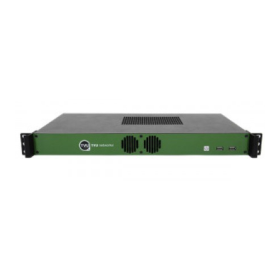
TVU Transceiver & Receiver Set Up and Operating Guide TVU Transceiver TX3200 Features and Indicators TVU Transceiver TX3200 Front Panel with Faceplate Label TVU Transceiver Front Panel Faceplate Power Button USB Ports Table 1 TVU Transceiver TX3200 Back Panel Connections (Standard SDI version) Label TVU Transceiver Back Panel Connections (SDI) Vent; Do not block AC Power 1 GigE Ethernet Port Display Port: Connect the supplied Display Port to VGA adapter for primary display purposes (see image below) HDMI Display Port USB Ports SDI Output SDI Input Audio Output Not Used Reference input: Allows for time sync with the television station’s broadcasting system Table 2 v5.5... - Page 6 TVU Transceiver & Receiver Set Up and Operating Guide VGA Adapter v5.5...
-
Page 7: Tvu Receiver: Network And Firewall Configuration
TVU Transceiver & Receiver Set Up and Operating Guide TVU Receiver: Network and Firewall Configuration TVU Networks recommends assigning a static IP address to the TVUPack receiver to ensure the network configuration remains stable. All the incoming ports referred to in this section are configurable. Please contact TVU Networks Customer Support if you wish to use a configuration other than the one specified in this documentation. Please configure your firewall or router as follows: 1. Allow TCP outgoing from the TVU receiver on port 3970. 2. Allow UDP/TCP outgoing from the TVU receiver on port 123. 3. Permit all TCP/UDP incoming traffic for port 8088 to receiver. 4. Forward all traffic arriving on port 8088 of the external firewall interface to the IP address of the TVU Receiver. This setup allows the TVUPack and receiver to automatically link with each other and permit video transport. Recommended firewall configuration for TeamViewer TVU Networks uses TeamViewer software to enable remote support and troubleshooting. To enable this software, please ensure that either port 80(TCP) or port 5938(TCP) are open for outbound connections. Recommended firewall configuration for remote control of TVUPack receiver from iPod or smartphone The TVUPack hotspot feature allows remote configuration of the TVUPack receiver settings from a smartphone. To enable this feature, permit all TCP/UDP incoming traffic for port 8288 to receiving terminal; forward all traffic arriving on port 8288 of the external firewall interface to the IP address of the TVU Receiver. This port is configurable. Recommended firewall configuration for the FTP server This feature allows files to be uploaded to the FTP server in the Receiver. To enable this feature, permit all TCP/UDP incoming traffic for port 21 to the receiving terminal; forward all traffic arriving on port 21 of the external firewall interface to the IP address of the TVU Receiver. This port is configurable. Recommended firewall configuration for remote configuration of a TVUPack from the receiver A TVUPack and its modems can now be configured from a remote location. To enable this feature, permit all TCP/UDP incoming traffic for port 22 to the receiving terminal; forward all traffic arriving on port 22 of the external firewall interface to the IP address of the TVU Receiver. This port is configurable. v5.5... -
Page 8: Bandwidth Recommendations
TVU Transceiver & Receiver Set Up and Operating Guide Recommended firewall configuration for the Return Video Feed This is a feature that can only be used on a TX3200 or GX3200 series Transceiver. It will allow camera operator in the field have the ability to watch a return video feed from the studio of their Pack transmission or from an SDI input at the Transceiver. To enable this feature, please ensure that you permit all TCP/UDP incoming traffic for port 8488. This port is configurable. In order to view a TVUPack feed remotely, ensure that port 10003 is open for all inbound traffic. To view an SDI feed remotely, make sure that port 10004 is open for all inbound traffic. Note: these are default ports, configurable if required. For more details, please contact TVU support by phone at +1.650.440.4812, by email at support@tvupack.com, or by skype at skype.tvupack. Bandwidth Recommendations Allowances should be made for bandwidth of incoming TVUPack transmissions based upon the following criteria: Each TVU receiver can utilize up to 20mbps of downstream bandwidth per live Pack feed. A minimum of 2mbps upstream bandwidth per Receiver is required for all features to function efficiently. We recommend a stable, low latency connection with guaranteed bandwidth for best results. v5.5... -
Page 9: Operating Tvu Transceivers & Receivers
TVU Transceiver & Receiver Set Up and Operating Guide TVU T & R PERATING RANSCEIVERS ECEIVERS TVU Transceivers and Receivers have two operating modes: Live and Record. You can pair multiple TVU transmitters to a Transceiver or Receiver, but can only receive video from one at a time. Depending on your specific license configuration, any number of TVU transmitters can be paired with your Receiver. For owners of the TVUPack HD version, please contact TVU Customer Support at +1.650.440.4812 for instructions on setting up the pack for HD mode. Live Viewing Mode Figure 1 Live Viewing Mode Screen Live Mode: Controls and Functions Label Live Mode: Controls and Functions Description System Information: Displays Receiver Name, PID (unique identifier for TVU Receiver), Build Version, Build Date and Record Time Remaining (if the optional Receiver record option is select). Quality Histogram and Post-Live Quality Histogram: Shows the total transmission encoding bit-rate over a period of time as well as gives users access to a post-live quality histogram. See Figure 2 and 3 Status panel: Displays error rate, line quality, and battery status. See Figure 2 Transceiver Information: Displays the input type and format, the output type and format, IFB status and IFB signal. See Figure 2 Refresh button: Resets the video stream. See Figure 2 Stop buttons (x2): Clicking on either Stop button ends the live transmission. v5.5... - Page 10 TVU Transceiver & Receiver Set Up and Operating Guide Label Live Mode: Controls and Functions Description Audio level light display: The two light displays provide visual monitoring of your audio levels. This displays dBFS audio input level at the Receiver. See Figure 2 Mode selection button and mode indicator lights: Use this button to toggle through the receiver operational modes. See Mode Selection (page 11) for more information Operational mode selection buttons: Use the operational mode buttons to choose an appropriate capture quality. Each mode has a default bit rate and delay. See Figure 4 Bitrate and delay controls: Sliding bars allow you to manually set the target bit rate and delay levels. See Figure 4 Datacard monitor panel: This monitor panel displays the current status of each data card. See Figure 5 Monitor Histogram: Displays throughput and IP address on each modem (mb/s). By right clicking on the histogram scale, you can configure the datacards of a particular transmitter. See “Configuring Modem Cards from the Receiver Interface” on page 16. Connection mode and Connection strength indication: The connection mode is displayed when available in the dark gray box between the carrier name as well as the connection strength. See Connection Mode and Connection Strength (page 14) for more information Reset: Provides a full power reset for a particular modem (TM8200 only). Use this feature when the modem is no longer able to connect or is having problems. On the TM8100, pressing “RESET” will force the modem to reconnect. See F on Figure 5 Scale: This drop down menu allows you to set the scale for the histogram graph. Once the scale has been changed, it will affect all of the histogram graphs displayed. Available selections are 1.2Mb/s, 2.4 Mb/s, 6Mb/s, and 12 Mb/s. Thumbnail of current video feed from TVUPack: The left-hand column of the TVUPack monitor features an icon of the current feed. If a transmitter is live, a red box will appear around the thumbnail image. GPS information: If a TVUPack transmitter is used with modems that support GPS, a display of the transmitter’s location can be retrieved. See GPS Locator (page 14) for more information IFB Indicator: The IFB indicator is displayed below the transmitter’s thumbnail picture. See Figure 8 Stop buttons (x2): Clicking on either Stop button stops the live transmission. Dynamic Sorting: Sort all of the TVU transmitters alphabetically or based on their live status. See Figure 9 Table 3 14 Status Panel Arranged vertically on the right hand side of the receiver panel are a number of indicators designed to help an operator make quality and troubleshooting decisions.
- Page 11 TVU Transceiver & Receiver Set Up and Operating Guide Transceiver Information Displays input type and input format of the transmitter, which are displayed as T Input and T Format respectively (D) (Figure 2). The output type and output format of the transmitter are shown as R Output and R Format. Lastly, the IFB status and the IFB Signal are displayed (E). The IFB signal has a strength meter that depicts the input level of the IFB. To stop the live transmission, users can press the “Stop” button on the status panel (G). Figure 2 Refresh Button If the video goes black or pixelates heavily and does not recover automatically within 15 seconds, click the Refresh button (F) to reset the video stream and reestablish the connection (Figure 2). Post-Live Histogram The Quality button (H) allows users to access the post-live histogram (Figure 2). The post live histogram allows users to recall a histogram of the entire past transmission and display it as a Web-based graph to review the overall performance (A) of that transmission over a certain period of time (B)(Figure 3). When the Quality button is selected, users will be directed to a webpage where they can access the post-live histogram. Users can look at a transmission that took place on a specific date as well as monitor the entirety of a live transmission (C)(Figure 3). The automatic refresh time can be set to a desired length (D) and users can search for a specific transmitter by typing in the PID v5.5...
- Page 12 TVU Transceiver & Receiver Set Up and Operating Guide number of the transmitter (E). Figure 3 Mode Selection The currently selected mode displays as a green-lighted tab. The modes that can be chosen are: • Live: Live mode is the primary interface to be used during a Live transmission. When this tab is selected, the status of each of the datacard network connections is displayed under the “Monitor” section of the interface and the Bitrate, Delay, and Operational Mode buttons are displayed. • Record: Record mode displays the store and forward interface for the preview, download, and management of Pack stored footage and files transferred via Auto Sync. Files transferred via FTP can also be accessed via this interface. Operational Mode Selection Depending on your news gathering environment, you can choose from the following preset bitrates and latencies (Figure 4): • Interview: Bitrate 2048, delay 2 seconds. • Normal: Bitrate 5120 delay 4 seconds. • Fast Moving: Bitrate 5120, delay 8 seconds. • SD: Bitrate 2048, delay 4 seconds. • Tapefeed: Bitrate 10240, delay 10 seconds. This mode is optimized for content with multiple scene changes. • User 1 & User 2: These are user-definable presets. To program these, users simply right click the preset they would like to define. Users can then name the preset (C), manually set latency (D), or check “Set Current”, which will save the current latency setting to that particular preset (E). Press “Apply” to program once finished (F). v5.5...
- Page 13 TVU Transceiver & Receiver Set Up and Operating Guide Figure 4 Bitrate and Delay Controls The TVU Receiver has a Smart VBR scaling system. This means that the unit will automatically adjust the bitrate in order to output the best quality picture based on the desire latency. In order to effectively take advantage of the smart VBR scaling system, set the your desired latency (A) and then set the maximum bitrate you would like to utilize (B)(Figure 4). When in “Live” mode, the error rate and picture quality will automatically be adjusted based on the desired latency and the available bandwidth in order to produce the highest quality picture. Datacard Monitor Panel The check boxes associated with each cards’ status bar enables or disables a particular datacard (A)(Figure 5). If unchecked, it will not be used to pass data. If checked on (default), it will be used. Individual read out panels show the carrier name (when available) of each active card (B). The slot number of each datacard is indicated in front of the carrier name (C). To retrieve the IP Address of a particular datacard, mouse over the name of that datacard. If no name is automatically provided and is displayed as <name>, you can input your own name. However, this will reset upon reboot. The color indicators displayed within the carrier name panel indicates the following status: • Red: Not connected • Green: Connected • Yellow: Dialing/Connecting • Gray: Disconnected or unplugged v5.5...
- Page 14 TVU Transceiver & Receiver Set Up and Operating Guide Figure 5 D E F Connection Mode and Connection Strength Indicator The connection mode (D) is next to the connection strength, which is indicated with three status bars (E)(Figure 5). If the bars are all gray, there is no connection. Three green bars indicate excellent connection strength. GPS Locator and Tracking When the transmitter is online, its name will be underlined underneath its thumbnail image. By clicking on the underlined name of the transmitter, the GPS data for that individual transmitter will appear. To locate all online transmitters at once, click “Locate All” at the top of the thumbnail column. Figure 6 The location pin will show the name of the TVUPack and the accuracy of the location. Additionally, a tracked of the path of the transmitter will be displayed to easily identify recorded content based on location. Simply mouse over a section of the tracked path and a thumbnail image of the recorded content at that location will appear. In order to improve the location accuracy, make sure the TVUPack is connected to a WiFi card. v5.5...
- Page 15 TVU Transceiver & Receiver Set Up and Operating Guide Note: If there is no real-time GPS data for a particular TVUPack, cache GPS data will be used for that Pack and the location pin will be yellow. Figure 7 IFB Indicator IFB Indicator The five-color indicators are as follows (Figure 8): • Red: IFB function is in use Red-Gray: Either the transmitter has gone offline and the IFB will recover when it • is back online or the transmitter goes live with a different receiver while you were speaking with the Pack via the IFB function • Green: IFB function is connected but not in use • Green-Gray: Either when the transmitter is live with another receiver or when the transmitter is using the IFB function to speak with another receiver • Gray: IFB Function not available for this transmitter Figure 8 To use the IFB function, click the IFB indicator so that it turns red. The IFB on/off status is also indicated in the “Status” panel on the left side of the interface. Additionally, if a particular TVUPack has an IFB function, the IFB is automatically turned on when that transmitter goes live. Once the live transmission is stopped, the IFB function will be turned off. v5.5...
-
Page 16: Configuring Modem Cards From The Receiver Interface
TVU Transceiver & Receiver Set Up and Operating Guide Dynamic Sorting To sort all of the TVU Transmitters alphabetically (B) or dynamically based on their live status (C), simply click the sort button (A) above the thumbnail images of the transmitters on the left side of the Receiver interface and choose the desired sorting method (Figure 9). Figure 9 Configuring Modem Cards from the Receiver Interface The modems can be configured on the TVUPack Receiver Interface by taking the following steps: 1) Right click the histogram of the modem you would like to configure Figure 10 2) A pop-up window will appear with the dial number, APN, and other necessary information v5.5... -
Page 17: Manual Selection Of Modem Carrier When Roaming
TVU Transceiver & Receiver Set Up and Operating Guide Figure 11 3) Hit “Apply” and the modem will be configured Manual Selection of Modem Carrier When Roaming This function allows users to manually select which carrier a particular modem will roam on. When roaming, simply go to the web-based interface for monitoring and controlling the transmitter and select the “Modems” table. To access the web-based monitoring and control interface, right click the histogram of the modem you would like to configure (Figure 10). See Configuring Modem Cards from the Receiver Interface on pg. 16 for more information. Simply select the desired carrier from the drop down menu of available carriers (A). Then click “Scan Carrier” (B)(Figure 12). The roaming modem will automatically generate all of the necessary information for that carrier. v5.5... -
Page 18: Adding An External Ip Source
TVU Transceiver & Receiver Set Up and Operating Guide Figure 12 Adding an External IP Source On the left side of the Receiver interface, there is a section for external sources such as YouTube (A)(Figure 13). In order to add an external source to the Receiver GUI, click the “+” on the section header (B). Figure 13 A pop-up screen will appear that will let you add an external source. Select the type of external source being added (A), insert the URL of the source and validate it (B), and name the source so that is easily recognized on the Receiver GUI (C)(Figure 14). Finally, click “Add”. A thumbnail icon of the added source will appear under the “External” section. v5.5... -
Page 19: Ip Streaming Output (Optional)
TVU Transceiver & Receiver Set Up and Operating Guide Figure 14 Note: The information of the external source can be edited by clicking on the round tool icon in the bottom left corner of the thumbnail image. IP Streaming Output (Optional) This optional feature allows users to take a live TVU transmission and easily output it to a third party decoder, file storage folder, or website such as YouTube. The live video transmission is encoded into an IP format and can be sent up to six different remote locations. If this feature is enabled, users can utilize it by clicking on the “External Encoder” tab at the top of the TVU Transceiver interface (A)(Figure 15). Note: A transmission must be live in order to use the IP Streaming Output feature to encode the video into an IP format and output it to a third party decoder, web streaming service or file folder. v5.5... - Page 20 TVU Transceiver & Receiver Set Up and Operating Guide Figure 15 Label IP Streaming Output Features and Functions IP Streaming Output tab Enables a single live transmission from the field to be encoded into an IP format and distributed to various locations. See Figure 16 for more information. Preview of live video source Video source information Audio source information Table 4 D E F B C Figure 16 Label IP Streaming Output Features and Functions Enables the selected live transmission from the field to be encoded into an IP format and distributed to any remote location. v5.5...
- Page 21 TVU Transceiver & Receiver Set Up and Operating Guide Encoding Bitrate Settings Audio Channels Port Number Audio Format Video Stream Format. See below (p. 21) for Video Stream URL formats and examples. IP Output URL Video Resolution Audio Encoding Bitrate Encoding Statistics including Variable Bitrate, Video Frames, and Frame Rate. Table 5 Video Stream URL Format and Examples File A local path. Example: C:\test.ts RTMP If there's a stream key provided by CDN, add the key in the URL with a colon, as below. Example: rtmp://1.10378966.fme.ustream.tv/ustreamVideo/10378966:VHgEzINxjh07XT TVt6iIXKQlY3aTMPEI M3U8 See the example below for proper URL for the M3U8 format. To play the M3U8 stream from your mobile device, open the URL with your mobile browser and type in: http://IP:Port/test.m3u8. IP is the IP address of the receiver, and the port number by default is 8488. Port number is subject to configuration. Example: C:\WWW\test.m3u8 UDP “IP” and “port” belong to the receiving destination. Example: udp://IP:Port v5.5...
-
Page 22: Record / Viewing Mode
TVU Transceiver & Receiver Set Up and Operating Guide Record / Viewing Mode Record mode allows you to preview, download, and delete stored footage. Figure 17 Record / Viewing Mode Screen Record Mode: Controls and Functions Please refer to Live Mode: Controls and Functions for a complete description and explanation. Label Record Mode: Controls and Functions Description Download tab - Files monitor panel: The Download tab shows the status, name, size, and completion percentage of all your downloaded files. Use the four buttons at the bottom of this panel to manage these files: Stop • Play • Delete • Download • For more information on downloading files, see AutoSync File Transfer Using Wireless Hotspot or Automatic Ingestion of USB Memory Stick Content to TVUPack (p. 27) FTP tab It is possible to upload video clips from an FTP to the TVUPack Receiver. The files uploaded to the FTP in the receiver will be displayed in this tab. Any type of file can be uploaded to the FTP server and most of the media files can be played back in the FTP tab and output to SDI. For further instructions, see Uploading Media Content to the Receiver Using the FTP (p. 30) Operations mode tab: This tab displays the current operation mode. v5.5... -
Page 23: Viewing, Downloading, And Deleting Stored Data
TVU Transceiver & Receiver Set Up and Operating Guide Label Record Mode: Controls and Functions Description Records control panel: Each time a video source is switched on and off, the TVUPack automatically creates a new recording on its internal SSD in a FIFO loop. This recording utilizes a completely different encoder than what is used for the Live transmission. This ensures that a high quality of version of any content (whether Live or not Live) is available. See Records Control Panel below (p. 23) for more information Edit bar: Use the start and end time triangular cursors on the green edit bar to select the footage to download by time. Stop buttons (x2): Clicking on either Stop button stops the preview of footage or the file download. Table 6 Records Control Panel The “Records” panel displays the number of recordings for each date on the scroll bar at the top. The green-circled numbers (A) that appear next to the dates show how many separate recordings have been captured on that day (Figure 18). Thumbnails of each recording (B) will display below the date bar. Each thumbnail also shows the start time for the clip. When you highlight a thumbnail, its start and end times appear in the left- hand column below the “Download All” button. Use the green edit bar below the thumbnails to mark “in” and “out” (C) on the recordings for extraction. Additionally, to see a preview of the video clip at a specific time, mouse over the desired time to see an image of the video recorded at that time (D). Figure 18 Viewing, Downloading, and Deleting Stored Data The TVUPack records all video it receives into a first in, first out (FIFO) drive. The last six hours of SD video or 1.5 hours of HD video are available for download from the TVUPack transmitter. After the storage limit is exceeded, the Pack records over the older video. If the TVUPack is currently in Live mode, begin by selecting Stop in the upper left corner. This will stop the live streaming video feed and change the status to Preview. The thumbnail of the current feed will display a stopped camera icon, also indicating no transmission. The system is now ready for managing the stored data. If you need to go back into Live mode, the stored data that is being exported or downloaded will be paused. The process of exporting or downloading will resume once Live mode is v5.5... - Page 24 TVU Transceiver & Receiver Set Up and Operating Guide disabled again. Exporting an entire Video Clip Take the steps outlined below to export an entire video clip: 1. Click on the arrow (A) to open the File Export and Rename drop-down menu (Figure 19 & 20). 2. Select the clip (B) to display in the task list (C) (Figure 19 and 21) 3. Click on the drop-down menu arrow and select the Export format (D) (Figure 21). 4. Rename the exported file in the Save As field (E). 5. Click Export to start the file export process (F). 6. Monitor the progress of the exported file (G). v5.5...
- Page 25 TVU Transceiver & Receiver Set Up and Operating Guide Figure 19 Record Mode Controls and Functions Screen Figure 21 Record Mode Controls and Functions Screen Figure 20 Take the following steps to select individual frames in a clip to export: 1. Navigate through stored data history by day or hour (A) (Figure 22). 2. Slide the start cursor (B) to the start of the time selected (Mark in). 3. Slide the end cursor (C) to the end of the time selected (Mark out). 4. Thumbnails of the in and out points will be generated by the system after a few moments. v5.5...
- Page 26 TVU Transceiver & Receiver Set Up and Operating Guide 5. Once the in and out points are selected, use the editing buttons (D) to download, play, delete, or stop the process. 6. Select the Export format (E) (Figure 23). 7. Re-name the exported file and click the Export button (F) to start exporting. 8. Select Export (G) to begin the process of preparing the video on the pack for transmission to the receiver. 9. When the file reaches 100%, (H) transfer to the Receiver hard drive is complete and ready to be played out. 10. The file can be found under location C:\TVUTransporterR\download\0x_____ where the last section is the unique PID of the TVUPack. On a receiver paired with multiple packs there may be up to 10 of these folders. Figure 22 Exporting a clip screen Figure 23 Exporting a clip screen v5.5...
-
Page 27: Autosync File Transfer Using Wireless Hotspot
TVU Transceiver & Receiver Set Up and Operating Guide AutoSync File Transfer Using Wireless Hotspot By using the TVUPack transmitter wireless hotspot feature and your laptop, you can automatically send files to the TVUPack Receiver. 1. Make sure the hotspot card is in Slot 9. 2. Search for the hotspot on your laptop or smart phone. The SSID will be TVUPACK_XXXX where X is the last 4 digits of the packs PID. 3. Connect to the SSID. 4. The password is the last 8 digits of the PID of the backpack (Note: All characters are uppercase). 5. Once the connection is established, obtain the IP address in the Connection Details. 6. Open a web browser and enter the IP address. 7. You should see the following: (Figure 24) Figure 24 AutoSync screen 8. Drag and drop files to be transferred into the AutoSync folder (Figure 24). Note: For assistance with other Operating Systems such as Mac OS, please contact TVU Customer Support at +1.650.440.4812. Automatic Ingestion of USB Memory Stick Content to TVUPack You can wirelessly transmit digital content from the TVUPack transmitter to the TVUPack Receiver. To do so, simply place the content on a USB memory stick and then connect the stick to the spare USB port on the TM8200 encoder unit. TVUPack will auto-detect the memory stick and automatically transfer the contents to its internal SSD hard drive. The content will then be available for wireless transmission to the TVUPack Receiver. Please note that the supported disk format is FAT32 only. Take the following steps to transfer content from a USB memory stick to TVUPack: v5.5... -
Page 28: Local Download Of Recorded Content To A Usb Memory Stick
TVU Transceiver & Receiver Set Up and Operating Guide 1. Create a directory named "autosyncimport" in the memory stick. 2. Copy the content you want transferred into the "autosyncimport" directory. 3. Plug the memory stick into any to the spare USB port on the TM8200 encoder unit. 4. Monitor the status of the file upload on the Pack’s LCD screen. Do not unplug the USB memory stick during the file upload as this may cause the system to malfunction. Local Download of Recorded Content to a USB Memory Stick By connecting a USB memory stick (FAT32 only) to a TVU transmitter while the video source is disconnected, the entire video content of the last session will be transferred to the memory stick in an NLE compatible format. Additionally, on the web-based monitoring and controls interface, the Recording tab (A) will lists the recorded sessions on the Pack SSD that are available for download (Figure 25). For more information on how to access the web-based monitoring and control interface, follow steps 1 and 2 on Configuring Modem Cards from the Receiver Interface on pg. 16 and choose the Recording tab (A)(Figure 25) at the top of the screen. Users can download any of these sessions to the connected USB memory stick by selecting the desired recording(s) followed by pressing “Copy” (B). Users will be warned if not enough space was available on the memory stick. Additionally, users can preview any recorded content by selecting a clip and pressing “Play” (C). Note: Playback is only available on iOS devices. v5.5... - Page 29 TVU Transceiver & Receiver Set Up and Operating Guide Figure 25 Once a file has been selected to download to the USB, a “Copying” message will appear in the interface while the file is copied and a “Complete” message would appear when finished. Note: The TVU Transmitter cannot be “live” to use this function. Deleting Uploaded Stored Content Take the following steps to delete stored content: 1. On the TVUPack Receiver screen, select the Record tab (A) (Figure 26). 2. Select the file you would like to delete (B). 3. Click the Delete button (C). Figure 26 Delete stored content screen v5.5...
-
Page 30: Uploading Media Content To The Tvupack Receiver Using The Ftp
TVU Transceiver & Receiver Set Up and Operating Guide Uploading Media Content to the TVUPack Receiver Using the FTP Take the following steps to upload media files from an FTP to the TVUPack Receiver 1. Log in to your usual FTP client 2. Retrieve the IP address of the TVUPack Receiver and plug it into the designated area on the FTP client 3. Type in the username and password of the TVUPack Receiver on the FTP. The username is the last four digits of the PID of the Receiver while the password is the last eight digits of the PID of the Receiver. 4. Drop the files you would like to upload into the FTP and they will be transferred to an FTP folder on the Local (C:) disk drive. These files will appear under the “Downloaded” tab on the TVUPack Receiver Interface. TVU Test Pattern When a TVUPack transmission stream is stopped by the user and goes offline, the preview screen on the receiver will display a TVU Test Pattern (Figure 27). When there is an unintentional interruption of the video stream, the preview screen on the TVU Receiver interface will go black for one minute and then switch over to the TVU Test Pattern. Figure 27 Accessing the WebR The TVU Receiver interface can be accessed from anywhere by using a standard webpage. In order to access the WebR, type in the follow URL: http://[The IP address of the receiver you would like to access]:8288/webr. v5.5... -
Page 31: Tvu Social
TVU Transceiver & Receiver Set Up and Operating Guide You will be brought to a login page. To login, the username is “tvu” and the password is the last 8 digits of the PID of the Receiver. Please note that all the characters are uppercase. This WebR has all the same features and functions as the Receiver GUI. Figure 28 WebR interface TVU Social TVU Social allows broadcasters to post captured still images from a TVUPack’s live video stream directly to social media networks such as Twitter with just the push of a button. By using the new TVU Anywhere Pro app on an iOS device to connect with the TVUPack transmitter via WiFi, field crews are able to easily capture and send images directly to supported social media platforms of their choice. The TVU Anywhere Pro app can be downloaded for free from the App store on your iPhone, iPad or iPad Mini. Once the app is downloaded and you have launched the app, simply tap on the Twitter icon (A) on the TVU Anywhere Pro interface (Figure 29). v5.5... - Page 32 TVU Transceiver & Receiver Set Up and Operating Guide Figure 29 You will be directed to a new page where you can easily capture and post images to Twitter (Figure 30). You will be asked if TVU Anywhere Pro can access your Twitter account. Select “Allow” in order to enable this feature. Note: Your iOS device must be connected to the TVUPack’s Hotspot in order to capture of picture of the live transmission and post directly to Twitter. See steps 1-4 under AutoSync File Transfer Using Wireless Hotspot on pg. 27 for directions on how to connect your iOS device to the Hotspot. Figure 30 v5.5...
-
Page 33: Tvu Social Media Manager Service (Optional)
TVU Transceiver & Receiver Set Up and Operating Guide Label TVUPack Anywhere Pro - Twitter Support Go back to the TVU Anywhere interface Tap the TVU logo to grab a snapshot of a TVUPack live video stream. You can also shake your phone, and a picture will automatically be captured and posted to your Twitter account. (See note below) Compose a Tweet in the message box Character count Choose a photo from your camera roll to Tweet. Note: You need to allow TVU Anywhere Pro to access your camera roll by selecting “Allow” when prompted in order to post to twitter. Table 7 Note: If you have multiple Twitter accounts logged in on your smart device, it will automatically post the snapshot of the TVUPack live video stream to the very first Twitter account that was added to your phone. When posting a picture from the camera roll, you will be prompted to choose a Twitter account. TVU Social Media Manager Service (Optional) TVU Networks also offers an additional service called the TVU Social Media Manager. This service allows broadcasters to have access to a cloud based web service that captures still JPEG images at regular intervals of the incoming live video streams from multiple TVUPacks in the field. This enables studio operators to select one or more JPEG images and post them directly to social media with the click of a button. These images are stored and can be used for future social media posts. TVU Support will provide you with your TVU Social Media Manger account information, and you can log into the web service here: www.tvupack.com/social Once logged in, you will see the TVU Social Media Manager interface and your paired TVUPacks (Figure 31). TVU Support will add your TVUPacks to your TVU Social Media Manager account. If you would like to add another TVUPack to your account, please contact TVU Support. v5.5... - Page 34 TVU Transceiver & Receiver Set Up and Operating Guide Figure 31 Label TVU Social Media Manager - Twitter Support Search for a specific TVUPack by typing in the Pack’s PeerID number Each paired TVUPack will be displayed with its PeerID number and then the stream of captured photos. The images are captured every one minute while the TVUPack is connected to a camera source. It does not matter if the TVUPack is “Live” or on “Standby”. Click to log out of the TVU Social Media Manager Authorize your Twitter account so that you can post from the TVU Social Media Manager directly to your Twitter feed. Be sure to enable pop-up windows in order to authorize your account. The username is displayed Table 8 To pair your Twitter account with the TVU Social Media Manager, click “Authorize”. A pop- up window will appear that will allow you to authorize the TVU Social Media Manager to post to your Twitter feed (Figure 32). If you are not already logged into your account on your computer, you will be promoted to log into your account. If you are already logged into your account on your computer, simply hit “Authorize App”. v5.5...
-
Page 35: Using The Ifb Feature (Optional)
TVU Transceiver & Receiver Set Up and Operating Guide Figure 32 To Tweet from the TVU Social Media Manager, simply click on the desired picture and you will be directed to a separate window in order to compose a Tweet (Figure 33). Figure 33 Compose a message in the box below the image. The character count is also displayed under the message box on the right. Once you are ready, click “Tweet” and your image and text will be posted to your Twitter feed. Using the IFB Feature (Optional) The Interruptible Feedback (IFB) feature allows your news operations center to speak v5.5... -
Page 36: Is+ (Optional)
TVU Transceiver & Receiver Set Up and Operating Guide directly to a TVUPack in the field without the need for telephone contact. The IFB option includes a mixer/preamp. The mixer has a USB port for connecting to your receiver and an XLR port for plugging in a microphone. Setting up this option is as simple as "plug and play." Receiver Pack Mixer/Preamp Figure 34 IFB Set Up On the TVUPack, connect a standard set of headphones to the 3.5mm audio jack on the body of the unit. (Located just to the left of the HDMI connector.) IS+ (Optional) IS+ is an advanced version of TVU Networks’ Inverse StatMux technology. With superior forward error correction technology, IS+ also has a higher throughput than the standard Inverse Statmux when under the same conditions. Additionally, with IS+, file transfers are between 2X and 4X faster than standard Inverse StatMux. This solution enables TVUPack to deliver resilient, HD professional broadcast-quality picture in even the most challenging wireless environments. Once IS+ has been installed on a TVUPack, a “+” sign will appear next the version number on the TVUPack user interface (Figure 35) and a “IS+” will appear to the right of the PID when mousing over the thumbnail of a particular transmitter on the Receiver interface (Figure 36). v5.5... - Page 37 TVU Transceiver & Receiver Set Up and Operating Guide Figure 35 Figure 36 If you would like to enable IS+, please contact TVU Support: Phone: +1.650.440.4812 Email: support@tvupack.com Skype: skype.tvupack v5.5...
-
Page 38: Contacting Tvu Networks
TVU Transceiver & Receiver Set Up and Operating Guide TVU N ONTACTING ETWORKS At TVU networks, we value our customers and are committed to ensuring a high level of satisfaction. Should you ever need assistance with your TVUPack, please contact us at one of our numbers below: Technical Support: Phone: +1.650.440.4812 Email: support@tvupack.com Skype: skype.tvupack Billing Questions: Phone: +1.650.969.6732 Corporate Address: 857 Maude Avenue Mountain View, CA 94043 v5.5... -
Page 39: Tvu Transceiver Tx3200 Technical Specifications
TVU Transceiver & Receiver Set Up and Operating Guide TVU T TX3200 T RANSCEIVER ECHNICAL PECIFICATIONS Table 9 A: T PPENDIX ROUBLESHOOTING IDEO UALITY Troubleshooting Video Quality Using the Status Indicators in Normal & Advanced Modes The Status counters offer a visual indication of specific technical aspects of the current live session. By interpreting these numbers it is possible for an operator to troubleshoot and optimize the quality of a session. Quality This is the real time effective bitrate of the transmission. If the system is set to VBR (variable bit rate) mode, this number will fluctuate between the configured maximum bitrate and the lowest bitrate the data connections can currently sustain. The maximum target bitrate is set by either using a preset mode in normal operation, or by using the bitrate slider in advanced mode. If the system is set to CBR (constant bitrate) this number will stay constant. Error rate indicators Error rate 8s. This indicates the percentage of uncorrected errors taken over an 8 second average. The aim is for this number to always be at zero during transmission. Error rate 1s. This indicates the uncorrected error rate over the last second. The aim is for this number to always be at zero during transmission. v5.5... -
Page 40: Line Quality Indicators
TVU Transceiver & Receiver Set Up and Operating Guide All uncorrected errors can contribute to undesirable video glitches. Any error rate greater than 0 indicates that the data connection is unable to operate cleanly in the current data environment. If attempting to operate in CBR (constant bitrate) mode try either lowering the required bitrate or switching to VBR to allow the system to adapt dynamically to conditions. If the system is already in VBR mode try increasing the delay to allow the error correction system more time to adapt to the network conditions. Line quality indicators Line quality shows the current error correction levels required for error free transmission at the configured settings. Line Quality 8s: This is the level of error correction (as an average over the last 8 seconds) required to sustain clean transmission. Line Quality 1s: This is the current level of error correction the system is using to sustain a clean transmission. The TVUPack uses multiple methods of error correction to ensure smooth clean video transmission in very challenging environments. Since the underlying network conditions are always a factor when working over multiple connections simultaneously, some error correction is always required. As a rule in difficult environments, the lower the latency, the more data is required for error correction to sustain a stable video transmission. This error correction, while highly effective, utilizes some of the limited bandwidth that is available in most situations. It is desirable where possible to limit the error correction required as it allows the system bandwidth for extra video quality. Operational Example 1: TVUPack is being used in a poor data service environment. In this scenario the receiver is set to Normal VBR mode, but the pack is inside a building with poor data service. The Quality indicator is seen to fluctuate between 2048 and 1000 as the signal strength and available data service varies. This indicates that the pack is using TVU’s Inverse Statmux to measure the available bandwidth and maximize throughput on a continuous basis. If the video quality is fluctuating two approaches may be used at the receiver to improve the video output consistency and stability. Suggestions • Try increasing the delay in 1s increments to allow the pack extra time to compensate for the dips in available bandwidth. • Try incrementally reducing the maximum bitrate so the fluctuations between high and low are less noticeable. Operational Example 2: TVUPack is being used in an environment with excellent data service. In this scenario the receiver is set to Normal VBR mode and all data cards are performing well. The Quality indicator stays constant at 2048 and rarely fluctuates. v5.5... -
Page 41: Appendix B: Vislink Hybrid Ip Microwave Integration Technology
TVU Transceiver & Receiver Set Up and Operating Guide Under these conditions it is possible that by switching to advanced mode and either increasing the bitrate (for improved video quality) or lowering the latency (for lower delay) may be practical. No action is required, but the system may be capable of enhanced performance if desired. Suggestions • Try increasing the bandwidth in 256k increments until the Quality indicator starts to become unstable and cannot sustain the new setting. • Try decreasing the delay in 0.2 second increments until the Quality indicator becomes unstable and does not stay consistent at the maximum bitrate. Operational Example 3: TVUPack is being used in an environment with average data service. In this scenario the TVUPack is being used in an interview talkback situation. The desire is to minimize latency but the bandwidth available to the system is limited and the Quality indicator is fluctuating between 750 and 1800. Uncorrected errors are appearing in the video output. Suggestions • Try increasing the delay in 0.5 second increments until the uncorrected errors stop appearing. • If delay is the most important factor, try decreasing the maximum bandwidth in 256k increments until the errors cease. Operational Example 4: In this scenario the receiver is set to Interview mode, but the pack is inside a building with poor data service. The line quality indicator increases up to approximately 50.00 but the Quality counter is down at 1000 and there are occasional errors. This indicates trouble on the underlying data networks. Suggestion Try increasing the delay in increments of 0.5 seconds to allow the system time to • compensate for poor conditions on the cellular network. B: V IP M PPENDIX ISLINK YBRID ICROWAVE NTEGRATION... -
Page 42: General Safety Information
TVU Transceiver & Receiver Set Up and Operating Guide microwave IP path will come and go seamlessly without interrupting the transmission. This unique modem module can easily be interchanged with the existing modem module by simply replacing the existing module with the new module that is integrated with Vislink technology. The microwave channel will connect seamlessly on the side of the TVUPack. No configuration should be required, but some settings are available via the web-based monitoring and control interface. For more information on how to access the web-based monitoring and control interface, follow steps 1 and 2 on Configuring Modem Cards from the Receiver Interface on pg. 16. Additional settings and features will be available under the “Microwave” tab on the web-based monitoring and control interface. Note: The Vislink Hybrid Modem Module requires a TM8200 with a 5-pin Modem Module interconnect. Please contact TVU Support for further details. General Safety Information The following safety requirements, as well as local site requirements and regulations, must be observed by personnel operating and maintaining the equipment covered by this manual to ensure awareness of potential hazards. This equipment has been tested and found to comply with the limits for a Class A digital device, pursuant to Part 15 of the FCC Rules. These limits are designed to provide reasonable protection against harmful interference when the equipment is operated in a commercial environment. This equipment generates, uses, and can radiate radio frequency energy. If not installed and used in accordance with the instruction manual, it may cause harmful interference to radio communications. Operation of this equipment in a residential area is likely to cause harmful interference in which case the user will be required to correct the interference at his own expense. About this Technical Note: This document is intended for use by qualified operators, installers, and service personnel. Users of this manual should already be familiar with basic concepts of radio, video, and audio. For information about terms in this manual, v5.5... -
Page 43: Vislink Rf Transport Overview
TVU Transceiver & Receiver Set Up and Operating Guide see Glossary of Terms and Abbreviations [Part No. 400576-1]. Pay special attention to Notes, Cautions, and Warnings. WARNING: RF power is present in the unit. Exposure to RF or microwave power can cause burns and may be harmful to health. Remove power from the unit before disconnecting any RF cables and before inspecting damaged cables and/or antennas. Avoid standing in front of high gain antennas (such as a dish antenna) and never look into the open end of a waveguide or cable where RF power may be present. NOTE: Hazardous RF radiation limits and recommended distances may vary by country. Ensure that all applicable state and federal regulations are observed when using this transmitter. The list below shows the Maximum Permissible Exposure [MPE] minimum safe distances from the antenna. [FCC OET Bulletin 65, August 1997] Antenna Gain 0 dBi 2 dBi 3 dBi 5 dBi 11 dBi Safe Distance 4 cm 6 cm 6 cm 8 cm 15 cm 1.57 in 2.36 in 2.36 in 3.15 in 5.9 in... -
Page 44: Lgr/Tvupack System Set-Up
TVU Transceiver & Receiver Set Up and Operating Guide Microwave Path BDC TVU PACK COFD Diversity Receiver IP Backhaul TVU Receiver LGR-1000 Collocated The Vislink Hybrid RF ASI over IP Modulator generates high power at 200 mW (milliwatts) and low power at 100 mW. A link barrel booster may also be incorporated when required for enhanced capability. Refer to the TVUPack image below. LGR/TVUPack System Set-Up This section describes how to configure a LiveGear Receiver to operate within a TVUPack system. First, set the WAN IP address of the LGR and depending on your network setup, set port forwarding. After configuring the LGR, TVUPack can be set to stream to the LGR. It is recommended that users preconfigure the transmitter and receiver together in the studio to ensure that the initial settings are analogous. It is also suggested that you test the system with a live video feed prior to sending a TVUPack team to a remote location. LiveGear Receiver • Connect AC Power Supply. • Connect Signal Input from RF Receiver • Connect Ethernet Cable [WAN port] • Set the rear Power Supply switch to On position. TVUPack Transmitter • Install SIM cards. • Connect video source. •... -
Page 45: Configuration Steps To Stream Video
TVU Transceiver & Receiver Set Up and Operating Guide Configuration Steps to Stream Video 1. Connect a laptop to the 4 port switch on the rear panel and apply power to the LGR by setting the Power Supply rocker switch on the rear panel and by pressing the front panel Power push button. Check the LCD to ensure that the initialization process has completed. 2. Browse to the default IP address of the LGR on the LAN at http://192.168.2.200. Log in using the UID/PW: admin/admin. 3. Browse to Setup > Network Settings 4. Set your IP address information in the WAN Configuration box and click Save. 5. Browse to Setup > LGR outputs a. Hit plus button on LGR outputs title bar b. Name the TVU output c. Select TVU as the input stream d. Enter TVU Transceiver IP and Port 8088 NOTE: Port forwarding may be needed from LGR system to TVU transceiver e. Save settings Figure 37 6. Apply power to TVUPack and wait for the initialization process to complete. Ensure that you have installed fully charged batteries [or use DC input]. Batteries v5.5... -
Page 46: Appendix C: Tvu Receiver Tr3700
TVU Transceiver & Receiver Set Up and Operating Guide must be recharged using an external charger. Allow time for TVUPack to boot up and optimize the cellular links for broadcast. a) Ensure that you have a secure connection to your video source at the Video Input BNC connector on the left side of the TVUPack transmitter. b) Set TVUPack to begin live video streaming. 7. Check the RF connections on the receiver to ensure RF link. The RF link is always active due to TVU’s Inverse Statmux video transport technique. Video will not be sent until the connection protocol is recognized by the TVUPack transceiver. 8. Once you have configured the LGR to operate with the TVU Pack system, check the TVUPack receiver Monitor display. The Vislink module will be shown as Interface 7, as shown in the example below. 9. If a good link is made in the system, Interface 7 will be lit green and show data transmission. Figure 38 C: TVU R TR3700 PPENDIX ECEIVER The TVU Transceiver is the companion decoder for all TVU transmitters and helps broadcasters monitor all aspects of a live transmission, including bit-rate and latency. The TR3700 model is slightly different from other TVU Transceivers because it allows for v5.5... - Page 47 TVU Transceiver & Receiver Set Up and Operating Guide two TVU transmitters to be live simultaneously on one transceiver with two independent SDI outputs and two separate TVU Receiver applications. Because of this function, the TR3700 requires some additional set-up. Normally, users would only attach one SDI cable to the one SDI output on the transceiver unit (A)(Figure 39). However, this unit has a second SDI output (B) on the back connections panel as seen in Figure 39. In order to access the second SDI output, simply plug an additional SDI cable into that outer connection. Figure 39 When TVU Support configures your TR3700, two receiver applications will be installed on the desktop in order for the user to access the user interface for both outputs (Figure 40). Figure 40 The TVU receiver GUI 1 will display the output plugged into the middle connection on the transceiver (A)(Figure 39). The TVU receiver GUI 2 will display the output plugged into the outer SDI output connection on the transceiver (B)(Figure 39). Both GUIs can be open at the same time in order to monitor and control the transmission of both TVU transmitters simultaneously (Figure 41). v5.5...
-
Page 48: Appendix D: Tvu Receiver Tr3750
TVU Transceiver & Receiver Set Up and Operating Guide Figure 41 For additional assistance, please contact TVU Support: Phone: +1.650.440.4812 Email: support@tvunetworks.com Skype: skype.tvupack D: TVU R TR3750 PPENDIX ECEIVER The TVU Transceiver is the companion decoder for all TVU transmitters and helps broadcasters monitor all aspects of a live transmission, including bit-rate and latency. The TR3750 model is slightly different from other TVU Transceivers because it allows for two TVU transmitters to be live simultaneously on one transceiver with two independent SDI outputs and two separate TVU Receiver applications. Additionally, it has a redundant power supply. it has a redundant power supply. Thus, if the one power supply fails (A)(Figure 43), the other power supply (B) will keep running in order to keep the TVU Transceiver powered up. In order to use the dual power supplies properly, both AC power supplies must be plugged into both of the AC power adapters on the back panel of the TR3750 (A)(B)(Figure 43). When one power supply fails, the TVU Transceiver will make a continuous beeping sound to alert users of the failure. Because of the dual outputs, the TR3750 requires some additional set-up. Normally, users would only attach one SDI cable to the one SDI output on the transceiver unit (G)(Figure 43). However, this unit has a second SDI output (I) on the back connections panel as seen in Figure 43. In order to access the second SDI output, simply plug an additional SDI cable into that outer connection. v5.5... - Page 49 TVU Transceiver & Receiver Set Up and Operating Guide TVU Transceiver TR3750 Front Panel Figure 42 Label TVU Transceiver TR3750 Front Panel Faceplate Power Button Table 10 TVU Transceiver TR3750 Back Panel C D E G H J K Figure 43 Label TVU Transceiver TR3750 Back Panel Connections (SDI) AC Power adapter AC Power adapter 1 GigE Ethernet Port Display Port: Connect the supplied Display Port to VGA adapter for primary display purposes. HDMI Display Port USB Ports SDI Output SDI Input Secondary SDI Output Audio Output Not Used Reference input: Allows for time sync with the television station’s broadcasting system Table 11 When TVU Support configures your TR3750, two receiver applications will be installed on the desktop in order for the user to access the user interface for both outputs (Figure v5.5...
-
Page 50: Appendix E: Tvu Transceiver Tx3250
TVU Transceiver & Receiver Set Up and Operating Guide 44). Figure 44 The TVU receiver GUI 1 will display the output plugged into the middle connection on the transceiver (G)(Figure 43). The TVU receiver GUI 2 will display the output plugged into the outer SDI output connection on the transceiver (I)(Figure 43). Both GUIs can be open at the same time in order to monitor and control the transmission of both TVU transmitters simultaneously (Figure 45). Figure 45 For additional assistance, please contact TVU Support: Phone: +1.650.440.4812 Email: support@tvunetworks.com Skype: skype.tvupack E: TVU T TX3250 PPENDIX RANSCEIVER The TVU Transceiver is the companion decoder for all TVU transmitters and helps broadcasters monitor all aspects of a live transmission, including bit-rate and latency. The TX3250 model is slightly different from other TVU Transceivers because it has a redundant power supply. Thus, if the one power supply fails (A)(Figure 47), the other power supply (B) will keep running in order to keep the TVU Transceiver powered up. v5.5... - Page 51 TVU Transceiver & Receiver Set Up and Operating Guide In order to use the dual power supplies properly, both AC power supplies must be plugged into both of the AC power adapters on the back panel of the TX3250 (A)(B)(Figure 47). When one power supply fails, the TVU Transceiver will make a continuous beeping sound to alert users of the failure. TVU Transceiver TX3250 Front Panel Figure 46 Label TVU Transceiver TX3250 Front Panel Faceplate Power Button Table 12 TVU Transceiver TX3250 Back Panel C D E G H Figure 47 I J Label TVU Transceiver TX3250 Back Panel Connections (SDI) AC Power adapter AC Power adapter 1 GigE Ethernet Port Display Port: Connect the supplied Display Port to VGA adapter for primary display purposes. HDMI Display Port USB Ports SDI Output SDI Input Audio Output Not Used Reference input: Allows for time sync with the television station’s broadcasting system Table 13 v5.5...
-
Page 52: Appendix F: Bit Central Integration (Optional)
TVU Transceiver & Receiver Set Up and Operating Guide F: B PPENDIX ENTRAL NTEGRATION PTIONAL TVU Support will assist with the integration. Once TVU Support has integrated Bit Central with your TVU equipment, set the receiver with the Bit Central configuration as the “Default Receiver” for file upload using ConfigT /Pack Web Interface (see pg. 16). This should only have to be set once. Using the AutoSync feature (either USB or HotSpot – see pg. 25), or the Clip Download function, transfer video files from the Transmitter to the TVU Transceiver. Once files are received at the Transceiver, they will be automatically ingested into the specified Bit Central server. v5.5... - Page 53 TVU Transceiver & Receiver Set Up and Operating Guide Files must be completely downloaded before they are ingested into the Bit Central server. For additional assistance, please contact TVU Support: Phone: +1.650.440.4812 Email: support@tvunetworks.com Skype: skype.tvupack v5.5...
Need help?
Do you have a question about the TR3700 and is the answer not in the manual?
Questions and answers