
Related Manuals for Dass DSP-123K5-OD

Summary of Contents for Dass DSP-123K5-OD
- Page 1 Operation and Installation Manual DASS Tech Photovoltaic Grid-Connected Inverter DSP-123K5-OD ver1.0...
-
Page 2: Table Of Contents
NOTICE 1. Caution for safety..............2 2. Product ................5 2.1 General ..............5 2.2 Specification..............8 3. Installation...............9 3.1 Configuration..............9 3.2 Installation place............9 3.3 Terminal connection diagram..........10 3.4 Wiring..............11 3.5 Cautions for mounting the inverter to the wall ........ 4. Operation.................15 4.1 Display..............15 4.2 Basic mode ..............15 4.3 Operation method............17 5. -
Page 3: Caution For Safety
1. Cautions for safety Cautions for safety must be kept under any circumstances in order to prevent accident or dangers for safe and right use. There are two types of caution in the manual, warning and attention, as below. Warning It possibly causes serious injury or death when violated. - Page 4 Attention Keep away from inflammables. If installed on or near combustible material, it could cause fire. When there is fire or smell, stop operation immediately and contact us right away. Shut off input power (solar cell) and output power (AC power) immediately when the inverter malfunctions.
- Page 5 (5) Disposal Dispose as a general industrial waste. (6) Others The pictures in this operation and installation manual occasionally drop the cover or breaker in order to explain in detail, however, you must strictly follow the guidelines in this manual for operation after installing the cover and breaker.
-
Page 6: Product
Confirm all setting values prior to operation 2. Product 2.1 General 2.1.1 Contents you should know before using the appliance If you misuse the inverter, it is operated abnormally or its performance may be depreciated. As the inverter might be broken or damage might impair the body seriously, use the inverter after understanding the application or installation manual enough in using the inverter. - Page 7 2.1.4 Preparation of devices or components for operation As the preparation for operation may be changed dependent on the installation environment more or less, prepare necessary materials and parts, i.e. – Multi Tester to check voltage and wiring, gearing tools to install T- type hanger and etc.
- Page 8 (3) Transformer-less circuit DSP-123K5-OD inverter is of transformer-less type and is suitable for the decentralized power system designed for industry, building and residential purpose. (4) Decentralized Power System and Profitability Photovoltaic power generation is a power generation type which can be installed wherever the sun shines exists.
-
Page 9: Specification
2.2 Specification Model NO. DSP-123K5-OD Voltage range(25 ℃) 100V ~ 500V MPPT Voltage range(25 ℃) 100V ~ 400V Input Rated voltage(25 ℃) 350V Start voltage(25 ℃) 150V Control method Max. Power Point Tracking control(MPPT) Rated output 3.1 kW Rated voltage... -
Page 10: Installation
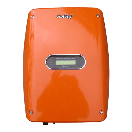
3. Installation 3.1 Configuration 1) DSP-123K5-OD 3.2 Installation place Install the Solar Inverter at the place satisfying following conditions. 1) Do not install the inverter at the place where the vibration exists. 2) As the lifetime of inverter is affected by surrounding temperature, make sure that the surrounding temperature around the place where the inverter is installed is lower than the allowable temperature (-10 ~ 50℃). -
Page 11: Terminal Connection Diagram
3.3 Terminal connection diagram If you uncover the cover in front on the lower part of inverter, you can find the terminal blocks as below. Read carefully this terminal connection diagram for wiring. 1) Description on main circuit terminal Terminal Terminal name Description on terminals symbol... -
Page 12: Wiring
For parallel operation(more than 2 inverters) and using monitoring, 485 communication terminal resistancedddd ON/OFF switch 485communication Terminal resistance connection : ON Terminal resistance release : OFF 3.4 Wiring 3.4.1 Main circuit wiring 1) Cautions for main circuit wiring For input power, connect the inverter’s inside connector to the inverter’s outside connector [+] inverter inside connector’s... - Page 13 2) Configuration and installation for DC connector Configuration Terminal Terminal Inverter Inside Connecter [ + ] Pole / Inner diagram [ - ] Pole / Inner diagram Terminal Terminal ( + ) Pole / Inner diagram ( - ) Pole / Inner diagram Inverter Outside Connecter...
- Page 14 ② Connect the connector to the cable which is connected to terminal CAP is only used for PV connector ※ Terminal coupling method is only connectable with terminal and connector shown above Step 2. Connection method of connector and inverter Turn the nut to be fixed Connector [+] Terminal Connector [-] Terminal...
-
Page 15: Cautions For Mounting The Inverter To The Wall
Unlocking & Separating 3.4.2 Communication circuit wiring 1) Notice of the communication circuit wiring Wiring of Control circuit terminal is to be used for communication connector. See the wiring diagram 3.3. 3.5 Cautions for mounting the inverter to the wall (Press fit) Inverter Wall BKT... -
Page 16: Operation
4. Operation 4.1 Display 4.1.1 Appearance 4.1.2Functions of display LED Status Description Indicates the input status from solar modules. Input (입력) (Green light: solar module is in normal operation) Grid (한전) Indicates the grid power system status. (Green light : grid power system is normal) Indicates the operation status of the inverter. - Page 17 4.2.3 Total generated power Display Unit Total : total generated power ▶▶▶▶▶▶▶▶▶▶ Present power generated →Total 500 kWh ▶▶▶▶▶▶▶▶▶▶ 3.1 kW 4.2.4 Maximum(Peak) generated power Display Unit Peak : maximum generation ▶▶▶▶▶▶▶▶▶▶ Present power generated →Peak 3.1 kW ▶▶▶▶▶▶▶▶▶▶ 3.0 kW 4.2.5 Daily(today) generated power Display Unit...
-
Page 18: Operation Method
4.2.8 Fault status (Displayed for 5 seconds) Display Type of error Fault number : number of times Fault status [001] E008 Under Voltage 4.3 Operation method 4.3.1 Check points prior to operation -. Check the wiring and installation status of the inverter. -. - Page 19 Factory Default, and Fault initialization deletes the fault records occurred in the past and sets to ‘ready’ mode. Controlling the inner keypad randomly shall cause malfunction of the inverter. You should contact DASS tech.. 5.1.4 Fault...
-
Page 20: Maintenance & Repair
6. Maintenance & repair 6.1 Types of error If any error occurs, it indicates such error and stops operation. When abnormal, its contents are displayed on the window of the keypad. Causes of faults and corrective actions Fault Type Indication Causes of errors Corrective actions Code... -
Page 21: Customer Service
6.2 Customer Service Check whether the inverter is normal or not. When the product breaks down, remember the date, time and indications on the fault. If the product does not work normally, check the follows for requesting customer service. Name of model Serial number of the product Purchased place Purchase Date... -
Page 22: Quality Assurance
• In case the product was repaired or revised at unofficial service center/man, not designated • In case of without the nameplate of DASS Tech • In case any failure occurs after the user dismantled, repaired or replaced our products •... - Page 23 Customer service +82-1588-7468 Tel: +82-43-218-5670 Fax: +82-43-218-5671 Headquarters: DASS Tech Co., Ltd. 109, Yangcheongsongdae-gil, Ochang-eup, Cheongwon-gu, Cheongju-si, Chungbuk, Korea http://www.dasstech.com Ver. 1.0...
Need help?
Do you have a question about the DSP-123K5-OD and is the answer not in the manual?
Questions and answers