
Related Manuals for Pulmonetic Systems LTV 1000


Summary of Contents for Pulmonetic Systems LTV 1000
- Page 1 www.ardusmedical.com ® Series Ventilator ® (LTV 1000, 950, and 900) Operator’s Manual P/N 10664, Rev. Y...
- Page 3 Fax: (763) 398-8400 E-mail: info@pulmonetic.com Website: http://www.pulmonetic.com ® ® ® ® 1000, LTV 950, LTV 900, and LTV are trademarks belonging to Pulmonetic Systems. Copyright © 2009 Pulmonetic Systems, Minneapolis, Minnesota. ® Operator’s Manual Series ventilator Page i p/n 10664, Rev. Y...
- Page 4 (60) days from date of shipment. 2) The internal battery is warranted for ninety (90) days from date of shipment. Pulmonetic Systems will, at its option, either repair, replace, or issue credit for products that prove to be defective during the warranty period.
- Page 5 Federal law restricts this device to sale by or on the order of a physician. European Regulatory Requirements per 93/42/EEC Medical Device Directives Pulmonetic Systems’ European Representative for vigilance reporting within the European Community is: MediMark® Europe Sarl.
- Page 6 LTV Series ventilator. ® Use and Maintenance - Any questions regarding installing, operating, or maintaining the LTV Series ventilator, should be directed to a certified Pulmonetic Systems’ service technician or Pulmonetic Systems. Avis important ® Fonctionnement dangereux - L'opération d'un ventilateur de la série LTV sans une excellente compréhension de ses attributs est dangereuse et risque de blesser le patient.
-
Page 7: Table Of Contents
Contents Warranty ............................. ii Notices ..............................iii Chapter 1 - Introduction ..............1-1 Operator’s Safety Information......................1-2 Warnings............................1-3 Cautions............................1-12 Symbols ............................1-18 Chapter 2 - Ventilator Overview............2-1 Intended Use ...........................2-1 Power/Supplies Required ........................2-2 Information/Assistance ........................2-3 Chapter 3 - Breath Types ..............3-1 Breath Types ...........................3-1 Volume Control Breaths ....................... - Page 8 Control Locking ..........................5-7 Control Retention ..........................5-7 Chapter 6 - Controls ................. 6-1 Assist/Control / SIMV/CPAP Modes....................6-1 Breath Rate ............................. 6-2 Control Lock ............................ 6-3 High Pressure Limit ......................... 6-4 Inspiratory / Expiratory Hold......................6-5 Inspiratory Hold..........................6-6 Expiratory Hold ..........................
- Page 9 Vte xxx ml ............................8-4 VE xx.x L............................8-4 I:E xx:xx ............................8-4 I:Ecalc xx:xx.............................8-4 Vcalc xxx Lpm..........................8-4 Chapter 9 - Ventilator Alarms............9-1 APNEA, APNEA xx bpm........................9-2 BAT EMPTY ............................9-3 BAT LOW............................9-5 DEFAULTS ............................9-7 DEFAULTS SET ..........................9-9 DISC/SENSE ..........................9-10 HIGH f ............................9-11 HIGH O PRES (LTV®...
- Page 10 Alarm Volume ..........................10-3 Apnea Interval..........................10-4 High Pressure Alarm Delay ....................... 10-4 Low Peak Pressure Alarm ......................10-4 High f............................10-5 High PEEP ..........................10-5 Patient Assist ..........................10-6 Exit ............................. 10-6 Vent Operations ..........................10-7 Variable Rise Time........................10-8 Variable Flow Termination ......................
- Page 11 Chapter 12 - Operating Procedure ..........12-1 To Turn the Ventilator On ......................12-1 Before Connecting the Ventilator to a Patient ................12-2 Procedure for Control Mode Set Up ....................12-4 Procedure for Assist / Control Mode Set Up..................12-5 Procedure for SIMV Mode Set Up ....................12-6 Procedure for CPAP Mode Set Up ....................12-7 Procedure for NPPV Mode Set Up ....................12-8 To Turn the Ventilator Off ......................12-9...
- Page 12 Unpacking the Ventilator – Instructions ..................C-1 Protective Boots...........................C-2 Protective Boot Removal ......................C-3 Protective Boot Installation ......................C-6 Patient Breathing Circuit – Connection Instructions ..............C-9 Patient Breathing Circuit – Connection Instructions ..............C-10 Oxygen Lines – Connection Instructions ...................C-12 Patient Assist Call System – Connection Instructions ...............C-14 Communications Port ........................C-15 LTM™...
-
Page 13: Chapter 1 - Introduction
Chapter 1 - NTRODUCTION This Operator’s Manual contains detailed information and instructions which when adhered to, ensure ® the safe and effective set up, use and simple maintenance of the LTV 1000, 950, and 900 Ventilators. It is designed for use by Respiratory Therapists or other qualified and trained personnel under the direction of a physician and in accordance with applicable state laws and regulations. -
Page 14: Operator's Safety Information
Operator’s Safety Information All Operators are to read and understand the following information about Warning, Caution and ® Note statements before operating the LTV Series ventilator. WARNING “WARNING” statements alert the reader to potentially hazardous situations which, if not avoided, could result in death or serious injury. -
Page 15: Warnings
Alarms Function Verification - All alarms must be verified as functioning properly on a daily basis. If any alarm malfunctions, immediately contact a certified Pulmonetic Systems’ service technician or Pulmonetic Systems. Patient Monitoring - Patients who are dependent on a ventilator should be constantly monitored by qualified personnel. - Page 16 INOP Alarm - If an INOP alarm occurs during operation, ventilate the patient using an alternative method, disconnect the ventilator, and immediately contact a certified Pulmonetic Systems’ service technician or Pulmonetic Systems. ®...
- Page 17 Improperly Functioning Ventilator - Operation of a ventilator that does not appear to be working properly may be hazardous. If the ventilator is damaged, fails Ventilator Checkout tests or malfunctions in any way, discontinue its use and immediately contact a certified Pulmonetic Systems’ service technician or Pulmonetic Systems.
- Page 18 PEEP Valve Rotation – Attempting to adjust the PEEP valve counterclockwise past zero (0) may damage the PEEP valve assembly or cause circuit leaks.Accessories Mounting Screws - Refer to the information contained in Pulmonetic Systems Replacement Screws Kit, P/N 11149, to determine the appropriate accessories mounting screws or accessories replacement screws location, type and length to use when removing or exchanging external accessories on an LTV®...
- Page 19 Vérification du fonctionnement des alarmes - Toutes les alarmes sonores et visuelles doivent être vérifiées quotidiennement. Si une des alarmes fonctionne de façon inadéquate, contactez votre technicien de service certifié de Pulmonetic Systems ou Pulmonetic Systems. Surveillance du patient – Un personnel qualifié doit constamment surveiller les patients qui sont reliés à...
- Page 20 électrique au patient ou à l'opérateur. Tout entretien doit être effectué par un technicien de service certifié de Pulmonetic Systems. Mode NPPV – Le mode NPPV n’est pas un mode de maintien des fonctions vitales continu et il n’est pas approprié...
- Page 21 Pièces, accessoires et options non autorisées - Des dommages à l'équipement ou des blessures au patient peuvent survenir suite à l'utilisation de pièces, accessoires et options non autorisées. Seuls les éléments expressément approuvés par Pulmonetic Systems doivent être utilisés en ®...
- Page 22 Alarmes de pression d'entrée de l'oxygène désactivées - Lorsque l'option de mélange d'oxygène n'est pas activée, les alarmes de pression d'entrée de l'oxygène sont désactivées. Circuits du patient – Les circuits du patient du Pulmonetic Systems, les valves expiratoires et les collecteurs d’eau sont expédiés propres, mais pas stériles.
- Page 23 AVERTISSEMENT Accessoires du circuit du patient - L’utilisation d’accessoires tels que les membranes vocales, les échangeurs thermohydriques et les filtres, produit une résistance additionnelle dans le circuit de patient et en cas de débranchement, elle risque d’empêcher la génération de l’alarme de basse pression.
-
Page 24: Cautions
Cautions CAUTION ® Ventilator Sterilization – To avoid irreparable damage to the LTV Series ventilator, do not attempt to sterilize it. Cleaning Agents – To avoid damaging the ventilator’s plastic components and front panel, do not use cleaning agents containing ammonium chloride, other chloride compounds, more than 2% glutaraldehyde, phenols, or abrasive cleaners. - Page 25 External Battery Pack - The External Battery Pack should only be connected to the LTV Series ventilator using the Pulmonetic Systems External Battery Cable (PN 10802). This cable is pre-wired and properly terminated to ensure safe connection of the External Battery Pack to the ventilator.
- Page 26 CAUTION Electrostatic Discharge – The use of electrically conductive hoses and tubing is not recommended. The use of such materials may result in damage to the ventilator from electrostatic discharge. ® External DC Power Source or External Battery - When connecting the LTV Series ventilator to an external DC power source or external battery, use only the approved method and connectors specified in Chapter 14 - Power and Battery Operation.
- Page 27 ATTENTION Stérilisation du ventilateur - Afin d'éviter des dommages irréparables au ventilateur de la série ® , ne tentez pas de stériliser ce dernier. Produits de nettoyage - Afin d'éviter d'endommager les composants plastiques et le panneau frontal du ventilateur, n'utilisez pas des produits de nettoyage contenant : chlorure d'ammonium, composés de chlorure, plus de 2% de glutaraldéhyde, ou phénol.
- Page 28 ATTENTION Entretien de la soupape d'expiration - La soupape d'expiration est une pièce fragile et peut être endommagée si : • Des précautions ne sont pas prises lors de sa manipulation ou de son nettoyage. • Des instruments de nettoyage ou des corps étrangers sont insérés dans celle-ci. •...
- Page 29 ® Bloc-piles externe – Le bloc-piles externe ne doit être branché qu’aux ventilateurs de la série LTV à l’aide du câble pour piles externes de Pulmonetic Systems (N pièce 10802). Ce câble est précâblé et ses terminaisons assurent une connexion sécuritaire entre le bloc-piles externe et le ventilateur.
-
Page 30: Symbols
Symbols Symbol Compliance Title Application ISO 3864 Caution (refer to Used to direct the user to the instruction accompanying manual where it is necessary to follow (Prev. IEC 348) documents) certain specified instructions where Symbol No.B.3.1 safety is involved. IEC 417 Fuse To indicate the fuse boxes, for example, and their location. -
Page 31: Chapter 2 - Ventilator Overview
® • Pulmonetic Systems does not recommend that the LTV Series ventilator be used outside of its intended use. Continuous Positive Airway Pressure Synchronized Intermittent Mandatory Ventilation Non-invasive Positive Pressure Ventilation ®... -
Page 32: Power/Supplies Required
Airline carriers typically allow only dry cell batteries on board aircraft. However, some airlines may allow an electrical cord to be plugged in if arranged in advance. Pulmonetic Systems recommends checking with the intended carrier well in advance before traveling. -
Page 33: Information/Assistance
Information/Assistance ® For additional information or troubleshooting assistance concerning the operation of the LTV Series ventilators, contact a certified Pulmonetic Systems’ service technician or: Pulmonetic Systems 17400 Medina Rd., Suite 100 Minneapolis, Minnesota 55447-1341 Phone: (763) 398-8300 Customer Care Center: (800) 754-1914 Fax: (763) 398-8400 E-mail: info@pulmonetic.com... - Page 34 ® Page 2-4 Series ventilator Operator’s Manual p/n 10664, Rev. Y...
-
Page 35: Chapter 3 - Breath Types
Chapter 3 - REATH YPES ® This chapter contains information regarding the breath types available on the LTV Series ventilator. It covers how breaths are initiated, limited and cycled, and when each type of breath is given. The following terms are used in discussing how breaths are given: Initiate What causes a breath to be given. -
Page 36: Volume Control Breaths
Volume Control Breaths For Volume Control breaths, the set Tidal Volume is delivered over the set Inspiratory Time and flow is delivered in a decelerating taper flow waveform. Peak flow is calculated based on the Tidal Volume and Inspiratory Time and the final flow is 50% of the peak flow. Volume breaths may be machine or assist type breaths. -
Page 37: Pressure Control Breaths
Pressure Control Breaths For Pressure Control breaths , flow is delivered to elevate the circuit pressure to the Pressure Control setting and maintain it at that pressure for the set Inspiratory Time. Pressure Control breaths may be machine or assist type breaths. Adjusting the Rise Time Profile changes the flow and pressure waveforms for Pressure Control breaths. - Page 38 Pressure Control Breaths (cont) Pressure Control breaths have an optional flow termination criteria. If PC Flow Termination is on Pressure Control breaths may be time or flow terminated. If the flow drops to the set FLOW TERM level before the inspiratory time is completed, the inspiration is cycled. Pressure Control and Pressure Support breaths do not compensate for PEEP.
-
Page 39: Pressure Support Breaths
Pressure Support Breaths For Pressure Support breaths, flow is delivered to elevate the circuit pressure to the Pressure Support setting and maintain it at that pressure until the flow drops below a variable percentage of the peak flow. Pressure Support breaths may also be cycled by a variable time limit, or by exceeding 2 breath periods. -
Page 40: Spontaneous Breaths
Spontaneous Breaths For Spontaneous breaths, flow is delivered to meet patient demand and maintain the circuit pressure at the measured PEEP from the previous breath. The breath is cycled when the flow drops below 10% of the maximum flow delivered during the breath, or below 3 lpm. Spontaneous breaths may also be terminated by exceeding 2 breath periods. -
Page 41: Chapter 4 - Ventilation Modes
Chapter 4 - ENTILATION ODES ® The LTV Series ventilator provides the following modes of ventilation: • Control • Assist/Control • SIMV - Synchronized Intermittent Mandatory Ventilation • CPAP - Continuous Positive Airway Pressure • Apnea Backup Ventilation • NPPV - Non-Invasive Positive Pressure Ventilation Each of these modes is described below. -
Page 42: Simv Mode
SIMV Mode SIMV mode is selected when SIMV / CPAP is selected and Breath Rate is set between 1 and 80. In SIMV mode, machine, assist and patient breaths may be given. For the first patient trigger detected within a breath period, an assist breath is given. For all subsequent patient triggers within the same breath period, spontaneous patient breaths are given. -
Page 43: Cpap Mode
CPAP Mode CPAP mode is selected when SIMV / CPAP is selected and Breath Rate is set to dashes “—”. In CPAP mode, when a patient trigger is detected, a patient breath is given. Breaths will be Pressure Support or Spontaneous breaths according to the Pressure Support setting. Pressure Pressure Pressure... -
Page 44: Apnea Backup
Apnea Backup ® The LTV Series ventilator provides an Apnea Backup mode of ventilation. Apnea Backup ventilation begins when the time since the last breath start is greater than the set Apnea Interval. When an apnea alarm occurs: • If an inspiration is in progress, the ventilator cycles to exhalation. •... -
Page 45: Nppv
NPPV The ventilator provides Non-invasive Positive Pressure Ventilation (NPPV) as a secondary mode that may be selected in addition to the primary ventilation mode. When NPPV mode is selected, ventilation is delivered according to the selected mode, however, a modified set of alarms are active. -
Page 46: Volume / Pressure Ventilation
Volume / Pressure Ventilation ® The LTV Series ventilator offers both Volume and Pressure ventilation. When Volume is selected, all machine and assist breaths are Volume Control breaths. Breaths are given according to the Tidal Volume and Inspiratory Time controls. For more information on Volume Control breaths, see Chapter 6 - Controls, Tidal Volume. -
Page 47: Ventilator Controls
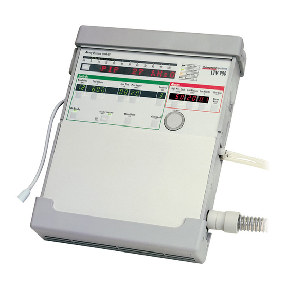
Chapter 5 - SING THE ONTROLS AND NDICATORS Ventilator Controls The following diagram shows how the front panel controls and displays are arranged. This illustration ® shows the LTV 1000. Pressure Control ventilation, Oxygen Blending, O Flush (O % (O Flush)) and Inspiratory / Expiratory Hold are not available on some models. -
Page 48: Setting A Control
Setting a Control ® There are 5 kinds of controls on the LTV Series ventilator. They are: Variable Controls Controls and alarms that have front panel displays. Buttons Push buttons that select an option or perform a function. Set Value Knob Used to set control values and navigate extended features menus. -
Page 49: Buttons
Buttons Button controls do one of three things: • Turn a feature on or off, such as Control Lock. • Toggle between two features, such as Volume or Pressure ventilation. • Perform a function, such as Manual Breath. Push the button to activate the feature or change the feature state. A green LED next to the button indicates when a feature is on. -
Page 50: Mechanical Controls
Mechanical Controls The ventilator PEEP setting is a manually adjusted mechanical control. Instructions for setting this control are given in Chapter 6 - Controls. WARNING Accuracy of PEEP setting - Variations in the patient’s breathing pattern and/or leaks in the patient circuit (including leaks around the tracheostomy tube cuff) can affect PEEP. -
Page 51: Bright, Dim And Blank Control Displays
Bright, Dim and Blank Control Displays Variable controls will be displayed at normal or dimmed intensity, or may be blanked. A display will be displayed at normal intensity: • When it is selected for change. All other displays will be dimmed. •... -
Page 52: Flashing Controls
Flashing Controls Variable controls and alarms will be displayed solid or flashing. A flashing control means one of the following things: • If you are changing a control setting, and the display flashes, you have reached a limited value for the control. -
Page 53: Control Locking
Control Locking The front panel controls may be locked so that settings cannot be accidentally changed. When the controls are locked, the Control Lock LED will be on. If you try to select or change a control while the Control Lock is on, the message LOCKED will be displayed in the display window and the Control Lock LED will flash. - Page 54 ® Page 5-8 Series ventilator Operator’s Manual p/n 10664, Rev. Y...
-
Page 55: Chapter 6 - Controls
Chapter 6 - ONTROLS ® This section explains how each of the LTV Series ventilator front panel controls work. Assist/Control / SIMV/CPAP Modes This button toggles between Assist/Control and SIMV/CPAP modes of ventilation. To toggle between the modes: 1) Push the mode button. The associated LED will flash for 5 seconds. 2) To confirm the mode change, push the mode button again while the LED is flashing. -
Page 56: Breath Rate
Breath Rate Use the Breath Rate control to establish the minimum rate of machine or assist breaths that the ventilator will deliver per minute. To set the Breath Rate: 1) Push the Breath Rate button. 2) Change the setting using the Set Value knob. Range: “- -”, 1 - 80 bpm NOTE When SIMV/CPAP is selected, the ventilator will be in SIMV or CPAP mode, depending on the Breath... -
Page 57: Control Lock
Control Lock ® The LTV Series ventilator front panel controls may be locked so that settings are not accidentally changed. Two different levels of difficulty can be set for control unlocking: Easy and Hard. Easy unlocking is the default and this setting is changed using the Extended Features menus . -
Page 58: High Pressure Limit
High Pressure Limit Use the High Pressure Limit to establish the maximum pressure permitted the patient circuit. When this limit is reached: • A HIGH PRES alarm is displayed • The audible alarm is sounded • Inspiration is terminated and exhalation begins The turbine is stopped to allow the circuit pressure to evacuate when the high pressure condition persists for more than four times the set inspiratory time or more than 3.0 seconds, whichever is less. -
Page 59: Inspiratory / Expiratory Hold
Inspiratory / Expiratory Hold Pushing the Insp/Exp (Inspiratory/Expiratory) Hold control button causes the ventilator to toggle between the following messages in the display window. Each push causes the next item in sequence to be displayed: INSP HOLD EXP HOLD Normal monitor display While INSP HOLD or EXP HOLD is displayed: •... -
Page 60: Inspiratory Hold
Inspiratory Hold An Inspiratory Hold maneuver holds the inspiratory phase of a delivered breath for a duration sufficient to determine Δ Pres pressure and static lung compliance of the patient. To perform the Inspiratory Hold maneuver: 1) Push the Insp/Exp (Inspiratory/Expiratory) Hold control button once and the display window will toggle from normal monitor display to INSP HOLD. - Page 61 NOTE The ventilator will not perform an Inspiratory Hold maneuver during Pressure Control, Pressure Support or Spontaneous breaths. If the button is held during exhalation or any non-volume inspiration: • The associated LED will be blinking. • All buttons that are not lockable will operate normally. •...
-
Page 62: Expiratory Hold
Expiratory Hold An Expiratory Hold maneuver holds the expiratory phase of a delivered breath for a duration sufficient to determine the AutoPEEP of a patient. To perform the Expiratory Hold maneuver: 1) Push the Insp/Exp (Inspiratory/Expiratory) Hold button twice and the display widow will toggle from normal monitor display to EXP HOLD. - Page 63 NOTE The ventilator will not perform an Expiratory Hold maneuver during Pressure Support or Spontaneous breaths. If the button is held during inspiration or during Pressure Support or spontaneous exhalation: • The associated LED will be blinking. • All buttons that are not lockable will operate normally. •...
-
Page 64: Inspiratory Time
Inspiratory Time This control sets the length of the inspiratory period for Volume Controlled and Pressure Controlled breaths. The Inspiratory Time setting, along with the Volume Control setting are used to determine the peak flow for Volume controlled breaths. While the Inspiratory Time is being updated, the Calculated Peak Flow will be displayed in the display window. -
Page 65: Low Minute Volume
Low Minute Volume The Low Minute Volume alarm sets the minimum expected exhaled Minute Volume. The exhaled Minute Volume is recalculated after every breath. If the Minute Volume does not meet or exceed the Low Minute Volume setting: • A LOW MIN VOL alarm is displayed •... -
Page 66: Low Pressure
Low Pressure The Low Pressure alarm can be set to apply to All breaths or to Volume Control and Pressure Control breaths only. (For information on selecting breath types, see Chapter 10 - Extended Features, Low Peak Pressure Alarm.) The Low Pressure alarm establishes the minimum expected circuit pressure for the selected breath types. -
Page 67: Low Pressure O
Low Pressure O Source (LTV 1000 Only) ® When selected, this option allows oxygen to be supplied from a low pressure / low flow oxygen source such as an oxygen concentrator or line mounted flow meter. Oxygen from the low pressure source is mixed with air inside the ventilator. - Page 68 Low Pressure O Source (cont.) NOTE The Oxygen Inlet High Pressure Alarm at 10 PSIG is only active when Low Pressure O Source is on. REMARQUE L'alarme de haute pression d'entrée de l'oxygène réglée sur 10 PSIG ne sera active que lorsque la source de basse pression O est activée.
- Page 69 Low Pressure O Source (cont) Low Pressure O Blending: Oxygen will be applied through the low pressure, low flow inlet. Use this chart to determine the approximate O flow required to deliver the desired FIO WARNING Inspired Oxygen (FIO ) Concentration – If the patient has a variable respiratory rate, his/her minute ventilation will fluctuate.
- Page 70 Low Pressure O Source (cont.) To determine the required O input flow: 1) Find the desired FIO (bottom of chart). 2) Calculate the patient’s minute ventilation rate by using the following formula: Tidal volume x breath rate. 3) Follow the FIO up to the applicable slanted VE (minute volume) line (right side of chart).
-
Page 71: Manual Breath
Manual Breath Use the Manual Breath button to deliver one (1) Machine breath. The breath will be a Volume Control or Pressure Control breath as defined by the current ventilator settings. The Manual Breath LED is on during the Manual Breath inspiration. To deliver a Manual breath: 1) Push the Manual Breath button. -
Page 72: O2 % (O2 Flush) (Ltv® 1000 Only)
For information on using a low pressure, low flow source, see Low pressure O2 source in this section. In addition to the existing internal O Inlet filter, P/N 14313, an External, In-Line Oxygen Filter (P/N 14470) is available from Pulmonetic Systems, Inc. ® Page 6-18 Series ventilator Operator’s Manual... - Page 73 % (O Flush) (cont) ATTENTION Contamination de la réserve d’oxygène — La précision de la capacité d’alimentation en oxygène ® des ventilateurs LTV peut être compromise par la présence de corps étrangers dans le système d’alimentation en oxygène. Afin de diminuer le risque de présence d’agents contaminants atmosphériques dans le ventilateur, assurez-vous que la réserve d’oxygène reliée au ventilateur est propre et filtrée de manière adéquate , et que le bouchon de l’orifice d’alimentation en oxygène est...
-
Page 74: On / Standby
On / Standby ® This button switches the LTV Series ventilator between Standby and On. When the ventilator is on, the On / Standby LED will be on. The ventilator will operate on external power if it is available, or internal battery, if there is no external power or the external power source is depleted. -
Page 75: Peep Valve
PEEP Valve The PEEP Valve establishes the Positive End Expiratory Pressure. The PEEP Valve is located on the exhalation valve assembly. PEEP should be set according to a physician's direction. To set the PEEP Valve: 1) Use the Select button to display the PEEP monitor in the display window. 2) Push and hold the PEEP Valve Lock, then rotate the PEEP valve clockwise to increase the pressure or counter-clockwise to decrease the pressure. - Page 76 PEEP Valve (cont) 3) Using the Airway Pressure display and the monitored PEEP as guides, adjust the PEEP Valve until the desired PEEP pressure is displayed and release the PEEP Valve Lock. Range: 0 to 20 cmH ® Page 6-22 Series ventilator Operator’s Manual p/n 10664, Rev.
-
Page 77: Pressure Control (Ltv ® 1000 & 950 Only)
Pressure Control (LTV 1000 & 950 Only) ® This optional control establishes the target pressure above 0 cmH O for Pressure Control breaths The inspiratory time for the Pressure Control breath is determined by the Inspiratory Time setting. The ventilator controls inspiratory flow to maintain the set circuit pressure for the set time. To set the Pressure Control level: 1) Push the Pressure Control button. - Page 78 Pressure Control (cont) NOTE Be sure that the Pressure Control setting is higher than the PEEP setting established by the mechanical PEEP valve. Be sure that Pressure ventilation is selected. If desired, select optional flow termination and flow termination percentage under Extended Features. If desired, select the rise time profile under Extended Features.
-
Page 79: Pressure Support
Pressure Support This optional control establishes the target pressure above 0 cmH O for Pressure Support patient breaths. If Pressure Support is set to dashes “—”, all patient breaths will be given as Spontaneous breaths. Inspiratory flow for Pressure Support and Spontaneous breaths is controlled to meet the patient demand. - Page 80 Pressure Support (cont) NOTE Be sure that the Pressure Support setting is higher than the PEEP setting established by the mechanical PEEP valve. If desired, select the flow termination percentage under Extended Features. The default setting is 25%. If desired, select the rise time profile under Extended Features. The default setting is Rise Time Profile 4.
-
Page 81: Select
Select Use this button to change the monitor in the display window and to select items in the Extended Feature menus. Monitored Data: The monitored data displays may be automatically or manually scrolled. To cycle through the available monitored data automatically from a halted scan: Push the monitor Select button twice within 0.3 sec. -
Page 82: Sensitivity
Sensitivity Use the Sensitivity control to establish the threshold level to allow the patient to flow trigger Assist and Patient breaths. A flow trigger occurs when: • The sensitivity is set to any value from 1 to 9, • And the ventilator is in exhalation phase, •... -
Page 83: Set Value Knob
Set Value Knob Use the Set Value Knob to establish control values and navigate extended features menus. Variable Controls: To change the setting for a variable control: 1) Push the button for the control to be modified. 2) Turn the Set Value knob clockwise to increase the value, or 3) Turn the Set Value knob counter-clockwise to decrease the value. -
Page 84: Silence / Reset
Silence / Reset Use this button to silence an alarm for 60 seconds, to reset an alarm, to start a 60 second preemptive silence period, and to permanently silence the Vent Inop and Standby alarms. Two important definitions for understanding how the Silence / Reset button works: •... -
Page 85: Tidal Volume
Tidal Volume Use the Tidal Volume Control to establish the volume of gas which the ventilator will produce and deliver during Volume Controlled breaths. Flow is delivered in a taper waveform over the set Inspiratory Time. The peak flow is calculated based on the Tidal Volume and Inspiratory Time with a maximum flow of 100 lpm and a minimum flow of 10 lpm. -
Page 86: Volume / Pressure Mode (Ltv® 1000 & 950 Only)
Volume / Pressure Mode (LTV® 1000 & 950 Only) Use this button to toggle between Pressure Control and Volume Control modes of ventilation. To toggle between the modes: 1) Push the mode button once. The associated LED will flash for 5 seconds. 2) To confirm the mode change, push the mode button again while the LED is flashing. -
Page 87: Chapter 7 - Displays And Indicators
Chapter 7 - ISPLAYS AND NDICATORS ® This section describes each of the LTV Series ventilator front panel displays. Airway Pressure The Airway Pressure display is a bar of 60 LEDs that is used to display the real-time airway circuit pressure. -
Page 88: Battery Level
Battery Level The Battery Level indicator shows the level of available internal battery power while running from the internal battery. When the ventilator is running from an external power source, the Battery Level indicator is off. When running from the internal battery at the nominal settings shown below, the indicator shows the following levels: Approximate Battery Alarm... - Page 89 Battery Level (cont) WARNING Battery run time - When the battery reaches the BAT LOW level, the ventilator will only run for approximately 10 minutes before generating a battery empty alarm (BAT EMPTY). The approximate times shown here are based on tests using the nominal settings, a new battery and a full 8- hour charge cycle as specified in Appendix A - Ventilator Specifications.
-
Page 90: Charge Status
Erreur de charge - Si le DEL de l'état de charge indique une erreur de charge, veuillez contacter immédiatement un technicien de service certifié Pulmonetic Systems. Utilisation de la batterie interne: La batterie interne est conçue pour être utilisée sur de courtes périodes pendant la commutation entre des connexions d’alimentation externe, les situations... -
Page 91: External Power
External Power The External Power indicator shows the level of external power while the ventilator is operating from an external power source. When the ventilator is running from the internal battery, the External Power indicator is off. When running from external power, the indicator shows the following levels: (See Chapter 7 - Battery Level for approximate battery time.) LED Color Power Level... -
Page 92: Nppv
NPPV The NPPV indicator LED is lit when NPPV mode is selected. NPPV mode is selected under the Extended Features. For more information on NPPV mode, see Chapter 4 - Ventilation Modes, NPPV and Chapter 10 - Extended Features. Patient Effort This LED is lit briefly each time a patient trigger is detected. - Page 93 Si cette condition se présente, le ventilateur doit être retiré du service, et vous devez immédiatement contacter votre technicien de service certifié de Pulmonetic Systems ou Pulmonetic Systems. ® Operator’s Manual...
-
Page 94: Automatic Or Manual Data Display Scrolling
Automatic or Manual Data Display Scrolling The monitored data displays may be automatically or manually scrolled. To cycle through the available monitored data automatically from a halted scan: Push the monitor Select button twice within 0.3 seconds. Pushing the Select button once while scan is active will halt scanning and the currently displayed data will remain in the display window. -
Page 95: Pip Xxx Cmh2O
PIP xxx cmH2O The Peak Inspiratory Pressure (PIP) monitor displays the greatest pressure measured during the inspiratory phase and the first 300 ms of exhalation Monitored PIP data is measured and displayed at the completion of inspiration. MAP xx cmH2O The Mean Airway Pressure (MAP) monitor displays a running average of the airway pressure for the last 60 seconds. -
Page 96: Vte Xxx Ml
Vte xxx ml The Exhaled Tidal Volume (Vte) monitor displays the tidal volume as measured at the patient wye. Vte data is recalculated and displayed at the completion of every exhalation. VE xx.x L The Minute Volume (VE) monitor displays the exhaled tidal volume for the last 60 seconds as calculated from the last 8 breaths. -
Page 97: Chapter 9 - Ventilator Alarms
Chapter 9 - ENTILATOR LARMS ® When conditions requiring immediate operator interaction are detected by the LTV Series ventilator, an alarm is generated. Some alarms can reset themselves, for instance, a high pressure alarm that is caused by a cough. Other alarms require some action from the operator and the audible and visual alarms will continue until the problem is corrected. -
Page 98: Apnea, Apnea Xx Bpm
APNEA, APNEA xx bpm When the time since the start of the last breath is longer than the set Apnea Interval, the APNEA alarm is generated. When an Apnea alarm occurs, the ventilator will enter Apnea Backup ventilation mode. For more information on Apnea Backup mode, see Chapter 4 - Ventilation Modes, Apnea Backup. -
Page 99: Bat Empty
BAT EMPTY When the ventilator is operating on internal battery power and the battery charge level falls below the empty threshold, the BAT EMPTY alarm is generated. For patient safety, this alarm can only be silenced once for 30 seconds and cannot be silenced preemptively. After the 30 seconds has elapsed, the alarm cannot be silenced again and will continue to sound and display until an alternate power source is provided or the battery is depleted and the ventilator goes INOP. - Page 100 BAT EMPTY (cont.) NOTE When the battery reaches empty, the ventilator may run for approximately 5 minutes before shutdown, based on the nominal settings, a new battery and a full 8 - hour charge cycle as specified in Appendix A - Ventilator Specifications. Actual run time may be more or less depending on ventilator settings, patient demand, and battery age.
-
Page 101: Bat Low
BAT LOW When the ventilator is operating on internal battery power and the battery charge level falls below the low threshold, a BAT LOW alarm is generated. When a BAT LOW alarm occurs: • The Battery Level LED is displayed Amber. •... - Page 102 BAT LOW (cont) NOTE Internal Battery Use: The internal battery is intended for use during short periods while switching between external power supply connections, emergency situations or short duration transports. The length of time the ventilator will operate on internal power is a function of factors such as settings, charge level and condition or age of the battery;...
-
Page 103: Defaults
Repeated occurrences of the DEFAULTS alarm may indicate a problem with the ventilator’s non- volatile memory. Please immediately contact a certified Pulmonetic Systems’ service technician. Control values are re-set to default values each time the ventilator is turned on, only if an invalid stored setting is detected during POST. - Page 104 DEFAULTS (cont.) The factory-set default Control settings are: ® • Some Controls are not applicable to all LTV ventilators; see Chapter 6 - Controls, for detailed information concerning specific Controls. Control - Default Control - Default Breath Rate - 12 bpm Low Pressure O Source - Off Control Lock - On...
-
Page 105: Defaults Set
DEFAULTS SET ® The DEFAULTS SET alarm is generated when the LTV Ventilator is first powered up after the SET DEFAULTS option has been used to reset all controls and extended features settings to their factory-set default values • Language, Time/Date Format and Com settings are not reset to default values when the SET DEFAULTS option is used in Extended Features. -
Page 106: Disc/Sense
DISC/SENSE When the ventilator detects one of the following conditions, the DISC/SENSE alarm is generated: • When a sense line is pinched or blocked. • When a sense line has become disconnected. • When a sense line is occluded (e.g., excessive condensation in the line). The ventilator detects circuit pressure during the beginning of each inspiration. -
Page 107: High F
HIGH f When the Total Breath Rate (f) exceeds the high breath rate and time period alarm values, the HIGH f alarm is generated. • To prevent nuisance alarms, the HIGH f alarm is suspended for the first 60 seconds of ventilator operation after power up and passing the Power On Self Tests. -
Page 108: High Opres
HIGH O PRES (LTV® 1000 Only) When the average oxygen inlet pressure exceeds the acceptable limit for the type of oxygen source, the HIGH O2 PRES alarm is generated. • If Low Pressure O Source is selected, the inlet pressure is >10 PSIG. •... -
Page 109: High Peep
HIGH PEEP When the patient circuit positive end expiratory pressure (PEEP) exceeds the High PEEP alarm setting, the HIGH PEEP alarm is generated. When a HIGH PEEP alarm occurs: • The HIGH PEEP message is flashed in the display window. •... -
Page 110: High Pres
High PRES When the pressure in the patient circuit is greater than the High Pressure Limit setting, the HIGH PRES alarm is generated. When this alarm occurs, any inspiration in progress is terminated and the exhalation valve is opened. The turbine is stopped to allow the circuit pressure to evacuate when the high pressure condition persists for more than four times the set inspiratory time or more than 3.0 seconds, whichever is less. - Page 111 HIGH PRES (cont.) The HIGH PRES alarm becomes inactive and is automatically silenced using the following criteria: High Pressure Circuit Pressure at which HIGH PRES alarm is silenced Limit Setting 31 to 100 cmH Less than 25 cmH 8 to 30 cmH More than 5 cmH O lower than current High Pressure Limit Setting 5 to 7 cmH...
-
Page 112: Hw Fault
The audible alarm is sounded. To reset the HW FAULT alarm: 1) Push the Silence / Reset button twice. 2) If the alarm occurs again, immediately contact a certified Pulmonetic Systems’ service technician or Pulmonetic Systems. This alarm is not available in NPPV mode. -
Page 113: Inop
INOP Alarm - If an INOP alarm occurs during operation, ventilate the patient using an alternative method, disconnect the ventilator, and immediately contact a certified Pulmonetic Systems’ service technician or Pulmonetic Systems. AVERTISSEMENT Ventilation alternative - Il est recommandé... -
Page 114: Low Min Vol
LOW MIN VOL When the exhaled minute volume (VE) is less than the Low Minute Volume setting, the LOW MIN VOL alarm is generated. • To prevent nuisance alarms, the LOW MIN VOL alarm is suspended for the first 20 seconds of ventilator operation after power up and passing the Power On Self Tests. -
Page 115: Low Opres (Ltv® 1000 Only)
LOW O PRES (LTV® 1000 Only) When the average oxygen inlet pressure is less than the minimum inlet pressure of 35 PSIG, the LOW O2 PRES alarm is generated. This alarm is only active when Low Pressure O Source is not selected and the oxygen concentration is set to greater than 21%. -
Page 116: Low Pres
LOW PRES When the peak inspiratory pressure for a selected breath is less than the Low Pressure setting, the LOW PRES alarm is generated. The Low Pressure alarm can be set to apply to all breaths (ALL BREATHS) or to Volume Control (VC) and Pressure Control (PC) breaths only. (For information on selecting breath types, see Chapter 10 - Extended Features, Low Peak Pressure Alarm.) When a LOW PRES alarm occurs: •... -
Page 117: No Cal Data, No Cal Monitor Display
Si cette condition se présente, le ventilateur doit être retiré du service, et vous devez immédiatement contacter votre technicien de service certifié de Pulmonetic Systems ou Pulmonetic Systems. For more information on the Calibration procedure, see the LTV® Series ventilator Service Manual. -
Page 118: Power Lost
POWER LOST When the ventilator operates on external power and switches to the internal battery, the POWER LOST alarm is generated. The change to internal battery is made when the external power voltage drops below the usable level. There is no interruption in ventilation. When a POWER LOST alarm occurs: •... -
Page 119: Power Low
POWER LOW When the ventilator is operating on external power and the voltage drops to the low level, the POWER LOW alarm is generated. When a POWER LOW alarm occurs: • The POWER LOW message is flashed in the display window. •... -
Page 120: Remove Ptnt
REMOVE PTNT When the ventilator is powered up in the Ventilator Checkout or Ventilator Maintenance modes, the REMOVE PTNT alarm is generated to remind you to remove the patient from the ventilator before proceeding. Use the Ventilator Checkout mode to check for correct operation of the displays and controls and to check the patient circuit for leaks. -
Page 121: Reset / Reset 1
See Appendix E - Event Trace for more information about events. Repeated occurrences of the RESET or RESET 1 alarm may indicate a problem with the ventilator’s hardware. Please immediately contact a certified Pulmonetic Systems’ service technician. REMARQUE Lorsqu'une alarme RESET ou RESET 1 se produit, vérifiez le suivi de l'événement pour obtenir plus... -
Page 122: Xdcr Fault
The XDCR FAULT alarm will remain active until a valid autozero can be done. If the XDCR FAULT persists, remove the ventilator from service and immediately contact a certified Pulmonetic Systems’ service technician or Pulmonetic Systems. -
Page 123: Alarm Status Messages
Alarm Status Messages f PEEP OFF The f PEEP OFF message is displayed when; • The High Breath Rate alarm is turned off by being set to HIGH f OFF and, • The High PEEP alarm is turned off by being set to HI PEEP OFF. This is an informational message only. -
Page 124: High F Off
HIGH f OFF The HIGH f OFF message is displayed when; • The High Breath Rate alarm is turned off by being set to HIGH f OFF and, • The High PEEP alarm (HIGH PEEP) is turned on. This is an informational message only. The message is displayed at power up, when monitored data is being scrolled automatically, and when no front panel activity is detected for 60 seconds. -
Page 125: Locked
LOCKED The LOCKED message is displayed when a button is pushed while the controls are locked. No audible alarm is given. When a LOCKED message is displayed: • The LOCKED message is flashed in the display window for 5 seconds or until the controls are unlocked. -
Page 126: Warmup Xx
WARMUP xx When the ventilator is first powered up, the transducers require up to 60 seconds of warm-up time before they will operate within their normal tolerances. During this warm-up period, the ventilator will not allow you to run the leak test or calibration. If you select an option that is not available during the warm-up period, the WARMUP xx message is displayed. -
Page 127: Chapter 10 - Extended Features
Chapter 10 - XTENDED EATURES This section describes the options and features available under the Extended Features Menus and how to access them. ® The Extended Features shown below are representative of an LTV 1000 ventilator. Refer to the descriptions of specific options or features contained in this chapter for their applicability to other ®... -
Page 128: Navigating The Extended Features Menus
Navigating the Extended Features Menus To enter the Extended Features menu (in normal ventilation mode): Push and hold the Select button for three seconds. To view the next item in a menu: Turn the Set Value knob clockwise. To view the previous item: Turn the Set Value knob counterclockwise. -
Page 129: Alarm Operations
Alarm Operations Use the Alarm Operations menu to set up alarm conditions that are not available directly from front panel controls. The menu is set up as follows: ALARM OP ALARM VOL APNEA INT HP DELAY LPP ALARM HIGH f HIGH PEEP PNT ASSIST EXIT... -
Page 130: Apnea Interval
Apnea Interval Use this menu item to establish the apnea interval. The apnea interval is the maximum time allowed between the beginning of one breath and the beginning of the next breath. To modify the Apnea Interval: 1) Push the Select button while APNEA INT is displayed. 2) APNEA xx sec is displayed. -
Page 131: High F
High f Use this menu item to set the high breath rate and time period alarm values. When the Total Breath Rate ( f ) exceeds the set high breath rate and time period alarm values, an audible alarm will be sounded and a flashing HIGH f message will be displayed. -
Page 132: Patient Assist
Patient Assist Use the PNT ASSIST menu item to configure the Patient Assist port output signal to be generated for use with remote alarm systems. • Allows for the changing of the patient assist alarm output signal used with remote alarm systems, which in turn will allow users a means of distinguishing the high pressure alarm (HIGH PRES) from other alarms. -
Page 133: Vent Operations
Vent Operations Use the Vent Operations menu to set up ventilator controls and options that are not available directly from front panel controls. The menu is set up as follows: VENT OP RISE TIME FLOW TERM TIME TERM PC FLOW TERM LEAK COMP NPPV MODE O2 FLUSH... -
Page 134: Variable Rise Time
Variable Rise Time Use the Variable Rise Time option to select the rise time profile for Pressure Control and Pressure Support breaths. The rise time profiles are numbered 1 through 9 where 1 is the fastest rise time and 9 is the slowest rise time. Starting with the fastest rise time, each time is 33% longer than the previous one. -
Page 135: Variable Flow Termination
Variable Flow Termination Use the Variable Flow Termination to select the percentage of peak flow used for cycling Pressure Support breaths. Pressure Support breaths are cycled from inspiration to exhalation when the flow reaches the set percentage of the peak flow, or when flow goes below 2 lpm. When Pressure Control Flow Termination is enabled, the Variable Flow Termination setting is used for flow termination of Pressure Control breaths as well. -
Page 136: Variable Time Termination
Variable Time Termination Use the Variable Time Termination to select the maximum inspiratory time for cycling Pressure Support breaths. Pressure Support Breaths are cycled from inspiration to exhalation if this time is reached before the flow reaches the set percentage of the peak flow. When a breath is cycled based on the time setting, the Pressure Support display is flashed briefly. -
Page 137: Pressure Control Flow Termination
Pressure Control Flow Termination Use the Pressure Control Flow Termination option to enable or disable flow termination for Pressure Control breaths. When this option is ON, Pressure Control breaths are cycled at the set percentage of the peak flow if it is reached before the set Inspiratory Time elapses. -
Page 138: Leak Compensation
Leak Compensation Use the Leak Compensation option to enable or disable tracking of the baseline flow to improve triggering when a circuit leak is present. When Leak Compensation is on, the system is gradually adjusted to maintain set sensitivity if the leak is stable and there is no autocycling. -
Page 139: Nppv Mode
NPPV Mode Use the NPPV Mode option to enable or disable Non-invasive Positive Pressure Ventilation (NPPV) mode. When NPPV Mode is selected, the NPPV Mode LED on the front panel is lit. For more NPPV information on NPPV mode, see Chapter 4 - Ventilation Modes, WARNING NPPV Mode - NPPV is not a life support mode and is not suitable for patients that require life... -
Page 140: O2 Flush (Ltv® 1000 Only)
O2 Flush (LTV® 1000 Only) Use the O Flush option to elevate the delivered FIO to 100% for a preset period of time. To initiate an O Flush: 1) Push and hold the O % (O Flush) button (FIO ) on the ventilator front panel for three seconds to initiate the elevation (ramp up) of delivered FIO to 100% for the preset number of minutes. -
Page 141: Control Unlock
Control Unlock Use the Control Unlock option to select the Easy or Hard unlocking method for unlocking the controls. The Easy unlocking method should be used when only trained personnel have access to the ventilator. The Hard method should be used when children or others may have access to the ventilator and you want to prevent accidental changes to the control settings. -
Page 142: Software Version
LTM Graphics Monitor compatibility can be verified by pushing the Select button when the LTV Model Number is displayed in the Extended Features menu. The message LTM will be displayed if the ventilator was originally manufactured or upgraded by Pulmonetic Systems to accommodate the LTM Graphics Monitor. ®... -
Page 143: Set Date
Set Date Use the Set Date option to view or set the current date stored in the ventilator. To view the Date: 1) Push the Select button while SET DATE is displayed. 2) The current date is displayed in the currently selected date format. 3) Push the Control Lock button to exit. -
Page 144: Set Time
Set Time Use the Set Time option to view or set the current time stored in the ventilator. To view the Time: 1) Push the Select button while SET TIME is displayed. 2) The current time is displayed. 3) Push the Control Lock button to exit. To modify the Time: 1) Push the Select button while SET TIME is displayed. -
Page 145: Pip Led
• The message LTM will be displayed on the right side of the display area if the ventilator was originally manufactured or upgraded by Pulmonetic Systems to accommodate the LTM Graphics Monitor. Push the Control Lock button or the Select button to return to the model number option. -
Page 146: Valve Home Position
Valve Home Position Use the Valve Home Position option to view the home position for the LTV’s flow valve. The home position is displayed as: VHome xxx where xxx is the home position for the valve installed in the ventilator. The home position is determined by the revision of the flow valve and is set when the ventilator is manufactured or when the flow valve is replaced. -
Page 147: O2 Cylinder Duration (Ltv® 1000 Only)
O2 Cylinder Duration (LTV® 1000 Only) Use the O Cylinder Duration option to calculate the approximate remaining usable time (in hours and minutes) of an external O cylinder. • To obtain an accurate duration time estimate, the current cylinder pressure must be entered prior to each calculation. -
Page 148: Exit
O2 Cylinder Duration (cont) 4) Turn the Set Value knob until CYL PRES is displayed, push the Select button and xxx psi is displayed. 5) Turn the Set Value knob until the applicable cylinder pressure is displayed, push the Select button and the cylinder pressure is set. -
Page 149: Transducer Autozero
Transducer Autozero Use the Transducer Autozero menu to manually schedule transducer autozeros and to view previous autozero results. Autozeros are automatically scheduled at appropriate intervals during ventilator operation, so manual scheduling of autozeros is not commonly performed, but may occasionally be done. -
Page 150: Bi-Directional Flow Transducer Differential Autozero
Bi-directional Flow Transducer Differential Autozero Use this item to view the Bi-directional Flow Transducer Differential Autozero results and schedule Autozeros to be run. To view the Bi-directional Flow Transducer Differential Autozero results: 1) The previous results, FDb xxxx P, are displayed. If the results are displayed as FDb xxxx -, the Bi-directional Flow Transducer is not installed on your unit. -
Page 151: Exhalation Flow Transducer Differential Autozero - Narrow
Exhalation Flow Transducer Differential Autozero - Narrow Use this item to view the Exhalation Flow Transducer Differential Autozero – Narrow results and schedule the Exhalation Flow Transducer Differential Autozero - Narrow to be run. To view the Exhalation Flow Transducer Differential Autozero – Narrow results: 1) The previous results, FDn xxxx P, are displayed. -
Page 152: Exhalation Flow Transducer Differential Autozero - Wide
Exhalation Flow Transducer Differential Autozero - Wide Use this item to view the Exhalation Flow Transducer Differential Autozero - Wide results and schedule the Exhalation Flow Transducer Differential Autozeros - Wide to be run. To view the Exhalation Flow Transducer Differential Autozero – Wide results: The previous results, FDw xxxx P, are displayed. -
Page 153: Real Time Transducers
Real Time Transducers Use the Real Time Transducer data to view the real time activity in the ventilator. The real time transducer menu is set up as follows: RT XDCR DATA xx.xx xx.xx xx.xx xx.xx FTw or FTn xx.xx Lpm x.xx LEAK xx.xx xx.xx... - Page 154 Display Real Time Data LEAK xx.xx Lpm Leak flow calculated from the differential pressure transducer, measured at the patient wye during exhalation. This value will be approximately 0.0 when the ventilator is autocycling. Eliminate autocycling by turning the sensitivity off before reviewing this measurement.
- Page 155 Chapter 11 - ENTILATOR HECKOUT ESTS This chapter details five test procedures accessed through the Vent Check menu and used to verify ® the proper operation of the LTV . These tests should be performed as shown in the schedule in Appendix B - Set Up / Maintenance for periodic maintenance and testing of the ventilator.
- Page 156 Disconnect the patient from the ventilator and ventilate the patient using an alternative method. Turn the ventilator off. Ensure that the AC Adapter is connected to a valid AC power source and verify that the External Power and Charge Status LEDs are illuminated. Push and hold the Select button.
-
Page 157: Alarm Test
Alarm Test Use the Alarm Test to verify that the audible alarm is working correctly. To run the Alarm Test: 1) Push the Select button while ALARM is displayed. 2) Verify that the audible alarm is sounded. • If a Patient Assist Call System or Remote Alarm is connected via the ventilator’s Patient Assist Port, verify the device also activates (audible/visual), as specified by its manufacturer. -
Page 158: Display Test
Display Test Use the Display Test to verify that the ventilator displays are working correctly. To run the Display Test: 1) Push the Select button while DISPLAY is displayed. 2) All segments of the 7-segment control displays, all dots of the dot-matrix window displays and all LEDs are illuminated. - Page 159 Display Test (cont) Verify displays are illuminated in the following colors: Display Color Display Color Airway Pressure Display Green Pressure Mode LED Green Display Window Assist/Control Mode LED Green Breath Rate Green SIMV/CPAP Mode LED Green Tidal Volume Green NPPV Mode LED Green Pressure Control Green...
-
Page 160: Control Test
Control Test Use the Control Test to verify that the ventilator buttons and the Set Values knob are working correctly. To run the Control Test: 1) Push the Select button while CONTROL is displayed. 2) SELECT is displayed in the display window. ®... - Page 161 Control Test (cont) 3) Test each control by pressing each button, one at a time. When pressed, verify that the name of the button pressed is displayed in the display window. Control names are as shown in the table below. Control Display Display Select...
-
Page 162: Leak Test
Leak Test Use the Leak Test to test the patient circuit for leaks. To run the Leak Test: 1) Attach all patient circuit accessories (such as water traps, heated circuits and humidifiers) to the patient circuit. ® 2) Connect the patient circuit to the LTV Series ventilator. - Page 163 Leak Test (cont) 5) To perform the Leak Test, the ventilator does the following: a) Closes the exhalation valve and sets the flow valve to a near-closed state. The display briefly shows HOMING VALVE. b) Elevates the turbine motor speed. The display shows SET TURBINE. If the display shows LEAK --- FAIL, see Chapter 15 - Troubleshooting for more information.
-
Page 164: Vent Inop Alarm Test
Vent Inop Alarm Test Use the Vent Inop Alarm Test to verify that the Inop Alarm is working correctly. To run the Vent Inop Alarm Test: To run the Vent Inop Alarm Test, the ventilator must be on (running) for at least 60 seconds and the Ventilator Checkout menu must be enabled. - Page 165 Verify the following; • A confirming audible chirp occurred after the alarm was silenced. If the Inop Alarm fails the test, discontinue use of the ventilator and immediately contact a certified Pulmonetic Systems’ service technician. ® Operator’s Manual Series ventilator Page 11-11 p/n 10664, Rev.
-
Page 166: Exit
Exit To exit the vent check mode and return to normal ventilation mode at any point proceed as follows: Enter normal ventilation mode: 1) Turn the Set Value Knob to scroll through the main menu entries (VENT OPS, ALARM OPS, VENT CHECK, etc.) until EXIT is displayed. -
Page 167: Chapter 12 - Operating Procedure
Chapter 12 - PERATING ROCEDURE ® This section describes how to turn the LTV Series ventilator on and off, and how to set up the ventilation modes. To Turn the Ventilator On 1) Connect the unit to an external source of power. The AC power adapter may be used or the ventilator may be connected to an external battery. -
Page 168: Before Connecting The Ventilator To A Patient
• Turn the ventilator off by pushing the On / Standby button. • Silence the alarm by pushing the Silence / Reset button. • Discontinue use of the ventilator and immediately contact a certified Pulmonetic Systems’ service technician or Pulmonetic Systems. - Page 169 Connect the Patient Circuit. To keep moisture out of the sense lines attached at the patient wye, be sure to connect the exhalation valve and circuit to the wye so the proximal sense lines are oriented up (see below). Connect a test lung to the circuit. Set any desired extended features options.
-
Page 170: Procedure For Control Mode Set Up
Procedure for Control Mode Set Up Set any desired Extended Features options and: Push the mode Select button twice to toggle the modes between Assist / Control and SIMV / CPAP. Select the Assist / Control mode. Push the mode Select button twice to toggle between Volume and Pressure ventilation. Select ®... -
Page 171: Procedure For Assist / Control Mode Set Up
Procedure for Assist / Control Mode Set Up Set any desired Extended Features options and: Push the mode Select button twice to toggle the modes between Assist / Control and SIMV / CPAP. Select the Assist / Control mode. Push the mode Select button twice to toggle between Volume and Pressure ventilation. Select ®... -
Page 172: Procedure For Simv Mode Set Up
Procedure for SIMV Mode Set Up Set any desired Extended Features options and: Push the mode Select button twice to toggle the modes between Assist / Control and SIMV / CPAP. Select the SIMV / CPAP mode. Push the mode Select button twice to toggle between Volume and Pressure ventilation. Select ®... -
Page 173: Procedure For Cpap Mode Set Up
Procedure for CPAP Mode Set Up Set any desired Extended Features options and: Push the mode Select button twice to toggle the modes between Assist / Control and SIMV / CPAP. Select the SIMV / CPAP mode. Push the mode Select button twice to toggle between Volume and Pressure ventilation for apnea ®... -
Page 174: Procedure For Nppv Mode Set Up
Procedure for NPPV Mode Set Up Set any desired Extended Features options and: Establish the ventilator controls for Control, Assist / Control, SIMV or CPAP mode as described in the preceding section. Establish the ventilator controls for Volume or Pressure ventilation as described in the preceding section. -
Page 175: To Turn The Ventilator Off
To Turn the Ventilator Off 1) Disconnect the ventilator from the patient. 2) Push and hold the On / Standby button for 3 seconds. The ventilator ceases operating, the audible alarm sounds continuously and the Vent Inop LED is lit. 3) Stop the audible alarm from sounding by pushing the Silence / Reset button. -
Page 176: Ltv® Ventilator Settings Checklist
LTV® Ventilator Settings Checklist ® The LTV Ventilator Settings Checklist may be used by caregivers as a reminder that all appropriate ® controls on the LTV were properly set, adjusted and/or recorded. Ordered Patient Name: Date: Controls: (Fill in (x.x), or Confirm (X)) Monthly Check-up Volume Mode: - or -... -
Page 177: Chapter 13 - Cleaning, Disinfecting And Sterilizing
Chapter 13 - LEANING ISINFECTING AND TERILIZING Cleaning the Ventilator All ventilator external surfaces should be cleaned prior to initial use, before and after each patient use, and as may be required. To clean the ventilator: 1) Wipe the exterior surfaces of the ventilator with a clean, damp cloth. The use of an anti-bacterial cleaning solution is recommended. -
Page 178: Cleaning Or Replacing The Fan Filter
Cleaning or replacing the Fan Filter To clean the fan filter: Using a small screwdriver, detach the fan filter grill from its housing. Remove the fan filter by squeezing the foam filter gently with your fingers and pulling it out. NOTE Hardware Fault -If you touch the fan blades while removing the fan filter grill or filter, a HW FAULT may occur. -
Page 179: Cleaning Or Replacing The Inlet Filter
Cleaning or replacing the Inlet Filter To clean the Inlet Filter: 1) Remove the Inlet Filter by squeezing the foam filter gently with your fingers and pulling it out. 2) Gently bathe the filter in a solution of mild detergent and warm water. 3) Rinse thoroughly in warm water. -
Page 180: Cleaning Or Replacing The O2 Inlet Filter
Unscrew and remove the barbed adapter from the oxygen block on the left side of the ventilator. In addition to the existing internal O Inlet filter, P/N 14313, an External, In-Line Oxygen Filter (P/N 14470) is available from Pulmonetic Systems, Inc. ® Page 13-4 Series ventilator Operator’s Manual... - Page 181 O Inlet Filter (P/N 14313) and O-Ring (P/N 10609), available from Pulmonetic Systems. 6) Replace the filter by sliding it back into the O inlet port. Replace the O-Ring, making sure it is completely tucked under the retaining lip on the inside of the O inlet port.
-
Page 182: Cleaning The Exhalation Valve And Reusable Patient Circuit
UV stable. Avoid exposure of the tubing to UV light. AVERTISSEMENT Circuits du patient – Les circuits du patient du Pulmonetic Systems, les valves expiratoires et les collecteurs d’eau sont expédiés propres, mais pas stériles. Le circuit du patient réutilisable doit être nettoyé... - Page 183 To clean the exhalation valve, sense line(s), wye and reusable patient circuit: For purposes of cleaning, the patient circuit with exhalation valve and all accessories must be detached from the ventilator. Disassemble the exhalation valve as shown and remove the diaphragm and compression spring. If using a patient circuit with a PEEP valve;...
- Page 184 To clean the exhalation valve and patient circuit, remove all gross particulate matter and bathe for a minimum of 10 minutes in 50% water and 50% vinegar, KlenZyme, or another enzymatic cleaner warmed to 95°F to 150°F (35°C to 65.5°C). Rinse gently for 2 minutes and use a low flow air source to eliminate any residual fluid.
- Page 185 CAUTION Reusable Patient Circuit Components - To avoid degradation of the reusable patient circuit components, do not exceed the following constraints: • 50 cleaning cycles or 1 year (whichever comes first) Steam Autoclave: • Pressure: 20 PSIG • Temperature: 275°F (135°C) •...
- Page 186 ATTENTION Composants réutilisables du circuit du patient – Pour éviter la dégradation des composants réutilisables du circuit du patient, ne dépassez pas les limites suivantes: • 50 cycles de nettoyage ou 1 an (le premier des deux prévalant) Autoclave à vapeur: •...
- Page 187 To reassemble the exhalation valve: Depress the lock and set the PEEP valve to "0". Insert the compression spring in the center hole of the PEEP valve. Make sure spring is securely seated inside the PEEP valve. Push the diaphragm on top of the spring. Make sure the diaphragm is correctly oriented with the narrow lip fitting up inside the PEEP valve.
- Page 188 ® Page 13-12 Series ventilator Operator’s Manual p/n 10664, Rev. Y...
-
Page 189: Chapter 14 - Power And Battery Operation
DC power adapter, an external battery or other suitable external DC power source such as the Pulmonetic Systems Universal Power Supply or Transport Battery System. The ventilator can also be powered for short periods of time by its own internal battery (see note below). -
Page 190: Using The Ac Adapter
Using the AC Adapter To run the ventilator from the Pulmonetic Systems AC Power Adapter: 1) Attach the power connector from the AC Adapter to the ventilator as shown here. 2) Connect the proper AC power cable (110V or 220V plug) to the AC Power Adapter. -
Page 191: Using An External Battery
External Battery Pack - The External Battery Pack should only be connected to the LTV Series ventilators using the Pulmonetic Systems External Battery Cable (PN 10802). This cable is pre-wired and properly terminated to ensure safe connection of the External Battery Pack to the ventilator. - Page 192 While the ventilator is connected to the external battery, the internal battery is being continuously charged. NOTE The External Battery Packs can only be recharged using the Pulmonetic Systems External Battery ® Charger. The External Battery Pack must be disconnected from the LTV Series ventilator before connecting to the External Battery Charger.
- Page 193 For more detailed information on using or charging the external batteries, or for information on ® replacing battery box or bag fuse, see the LTV Series External Battery Kit Operator's Manual. The battery may be set and operated from any position, but always secure the battery box in place ®...
-
Page 194: Using The Automobile Cigarette Lighter Adapter
Dans cette situation, le ventilateur déclenche une alarme PAS ALIM SEC et utilise la batterie interne du ventilateur comme source d’alimentation. Pulmonetic Systems Automobile Cigarette Lighter Adapter P/N 10703. ® Page 14-6 Series ventilator Operator’s Manual... - Page 195 CAUTION Automobile Cigarette Lighter and Power Outlets - Automobile cigarette lighter and power outlets are normally wired for a positive center contact and ground sleeve contact. Connecting the ventilator to an improperly wired outlet will cause the adapter fuse to blow and may damage the adapter or the ventilator.
- Page 196 CAUTION Release Button - To avoid damaging the ventilator or the power connector, push the release button on the connector before removing it from the ventilator power port or the power port pigtail connector. ATTENTION Bouton de déclenchement – Pour éviter d'endommager le ventilateur ou le connecteur d'alimentation, appuyer sur le bouton de déclenchement situé...
- Page 197 4) Verify the ventilator is being powered by the vehicle battery, through the Automobile Cigarette Lighter Adapter. • The vehicle battery is powering the ventilator if the EXTERNAL POWER LED shows green. • An amber EXTERNAL POWER LED and/or a POWER LOW alarm indicates the external power level is low.
-
Page 198: Replacing The Automobile Adapter Fuse
5) Replace the contact point and tighten the nut. The Universal Power Supply (UPS) The Pulmonetic Systems Universal Power Supply kit is a rechargeable external power source and backup system for Pulmonetic Systems’ devices. It has the following features: •... -
Page 199: The Sprintpack Li-Ion Power System
The SprintPack Li-Ion Power System ® The SprintPack™ is a portable, re-chargeable external power source. It accepts external LTV power sources and has the following features: • Two no-maintenance high capacity HotSwap™ re-chargeable Lithium Ion batteries providing ® up to six hours of mobile power for the LTV ventilator. -
Page 200: Caring For The Internal Battery
AC power source for 24 hours. If the battery Charge Status LED is not illuminated green within 24 hours, or if it is illuminated red, immediately contact a certified Pulmonetic Systems’ service technician or Pulmonetic Systems. •... -
Page 201: Chapter 15 - Troubleshooting
For information on resolving problems that are not listed here, contact Pulmonetic Systems. ® Operator’s Manual... -
Page 202: Displays And Buttons
Displays and Buttons Some of the symptoms listed in this section are part of the normal operation of the ventilator and do not indicate any problem with the ventilator. They are included here for completeness. Symptoms Possible Causes What to Do Pressure Control Pressure Control breath Pressure Control breaths are normally... - Page 203 (See page 5-6 for an explanation of Control Limiting.) Internal problem with Do a control test (see page 11-6 for instructions). the ventilator. If the control does not operate, immediately contact a certified Pulmonetic Systems’ service technician. ® Operator’s Manual Series ventilator Page 15-3...
- Page 204 Symptoms Possible Causes What to Do ® Can’t unlock the Hard unlock method Two unlock methods are available on the LTV controls. selected under CTRL Series ventilator: (See pages 5-7 and 10-15 for UNLOCK. an explanation of CTRL UNLOCK.) To unlock in EASY mode, push the Control Lock button.
-
Page 205: Ventilator Performance
Ventilator Performance Symptoms Possible Causes What to Do Ventilator is Sense lines are The sense lines are not designed to be removed autocycling, reversed. from either the wye or the luer fittings. If the monitored volumes sense lines have been removed and replaced are very small, RT incorrectly, they may not seal correctly when XDCR DATA item... - Page 206 Symptoms Possible Causes What to Do continued… Low side sense line or Check high and low pressure sense lines to be elbow at patient wye sure they are correctly attached and securely Monitored volume is loose or leaking. seated at both the ventilator and wye ends. high.
- Page 207 Symptoms Possible Causes What to Do continued… Exhalation drive line Check the exhalation drive line at both the leaking or loose. ventilator and exhalation valve ends. Verify the Monitored volume is line is securely seated and not leaking. Exhalation valve low.
- Page 208 Symptoms Possible Causes What to Do Continued… High or low side sense Check high and low pressure sense lines to be line or elbow at patient sure they are correctly attached and securely Delivered pressure is wye loose or leaking. seated at both the ventilator and wye ends.
- Page 209 Symptoms Possible Causes What to Do Delivered pressure is Diaphragm is Open the exhalation valve and remove the high. incorrectly seated in diaphragm and spring. Reseat the spring and exhalation valve. diaphragm valve and snap the peep valve or Monitored pressure is peepless valve cap back in place.
- Page 210 Low O correctly calculated and set using the Input O Source selected. Flow Chart (see page 6-15). inlet flow too high Pulmonetic Systems recommends the use of an when Low O Source monitor to verify delivered O %. Adjust the selected.
- Page 211 Low O Source correctly calculated and set using the Input O selected. Flow Chart (see page 6-15). Pulmonetic Systems recommends the use of an monitor to verify delivered O %. Adjust the entrained O flow so the monitored value shows the desired FIO .
- Page 212 Symptoms Possible Causes What to Do High side sense line or Check high and low pressure sense lines to be Continued… elbow at patient wye sure they are correctly attached and securely PEEP not working. loose or leaking. seated at both the ventilator and wye ends. PEEP low.
- Page 213 Symptoms Possible Causes What to Do Ventilator gets Patient circuit leaks. Perform a Leak Test and reseat or replace the excessively hot. Ventilator must run leaking parts or connections. See page 11-8 for harder to maintain instructions. PEEP. Internal problem with Immediately contact a certified Pulmonetic the ventilator.
-
Page 214: Power And Battery Operation
Power and Battery Operation Problem Possible Causes What To Do The ventilator does Faulty power Verify the power cord for the AC adapter is fully not power up. connection, AC power seated. Connect the ventilator to a verified source or adapter and source of AC power. - Page 215 Problem Possible Causes What To Do Battery doesn’t reach Internal battery deeply Charge the internal battery for 24 hours by full charge. discharged. connecting the external AC adapter and plugging it into a good AC source. If the battery is deeply Battery depletes too discharged, it may take several cycles of quickly.
-
Page 216: Alarms
HW FAULT or RESET may be caused by ESD. If these alarms reoccur, and for other alarms that do not usually occur during normal operation, follow the instructions in this section or immediately contact Pulmonetic Systems. Multiple Alarm Priorities When multiple active alarms occur at the same time, the alarm with the highest priority level will be displayed. - Page 217 Alarm Name Displayed Alarm Priority Level ® 9. LOW O2 PRES (LTV 1000) Pressure Low High ® 10. HIGH O2 PRES (LTV 1000) Pressure High High 11. DEFAULTS Defaults High 12. NO CAL DATA No Calibration Data High 13. HW FAULT Hardware Fault High 14.
- Page 218 Symptoms Possible Causes What to Do HIGH PRES occurred Alarm silence was already The ventilator alarms can be silenced for but alarm did not active (Silence/Reset LED 60 seconds by pushing the Silence Reset sound. is red). button. If the alarm is already silenced (Silence/Reset LED is red), it will not sound again until the silence period expires.
- Page 219 Symptoms Possible Causes What to Do continued… Sense lines occluded or Check high and low pressure sense lines pinched. to be sure they are correctly attached and Ventilator won’t securely seated at both the ventilator and exhale, repeated wye ends. HIGH PRES alarms, Verify lines are not occluded or pinched.
- Page 220 Internal problem with the If problem reoccurs, immediately contact ventilator. a certified Pulmonetic Systems’ service technician. RESET alarm occurs Internal battery depleted. This is a normal. Clear the alarm and after ventilator is...
- Page 221 Clear the alarm. Reduce static causing conditions in the operating environment. Internal problem with the If problem reoccurs, immediately contact ventilator. a certified Pulmonetic Systems’ service technician. Repeated HIGH f Total Breath Rate (f) exceeds Check HIGH f alarm values. See page alarms.
- Page 222 Symptoms Possible Causes What to Do Remote Alarm PNT ASSIST option set to Set PNT ASSIST option to PULSE. See System (dual tone NORMAL. page 10-6 for instructions. system) only Defective Remote Alarm Contact Remote Alarm System generates one System. manufacturer or service personnel.
-
Page 223: Checkout Test Failures
Checkout Test Failures Symptoms Possible Causes What to Do Alarm Test Alarm volume set too high. Set the alarm volume under the Extended Features Menu. (See page 10-3 for an Audible alarm level explanation of the ALARM VOL feature.) excessive. Alarm Test Alarm volume set too low. - Page 224 Symptoms Possible Causes What to Do Control Test Wrong model selected in Immediately contact a certified Pulmonetic maintenance mode. Systems’ service technician. Volume / Pressure Mode button, Pressure Control button, O Flush) button, or Low Pressure O Source button do not display message when pushed.
-
Page 225: Test Lung Operations
Pressure> 40 cmH O used The compliance characteristics of some higher than set on small test lung small test lungs (Pulmonetic Systems or pressure on test lung. (Pulmonetic Systems or Siemens 190) cause incorrect readings Siemens 190.) when high pressures are used. For these... - Page 226 ® Page 15-26 Series ventilator Operator’s Manual p/n 10664, Rev. Y...
- Page 227 Appendix A - V ENTILATOR PECIFICATIONS Modes and Breath Types Breath Types Volume Control, Pressure Control, Pressure Support, Spontaneous Modes Control, Assist/Control, SIMV, CPAP, NPPV, Apnea Backup Variable Controls Control Range Tolerance Backup Pressure Trigger -3 cmH ± 2 cmH Breath Rate “--”, 1 to 80 bpm ±...
- Page 228 Control Range Tolerance Pressure Control 1 to 99 cmH ± 2 cmH O or 8% whichever is greater, steady-state only Pressure Control Flow On, Off Termination Pressure Support “--”, 1 to 60 cmH ± 2 cmH O or 8% whichever is greater, steady-state only.
- Page 229 Fixed Alarms Control Range Tolerance / Indicators Default Settings EEPROM problem detected DISC/SENSE Positive (exhaled) airway flow during first 200 ms of (Low Pressure Sense inspiration and exhaled tidal Line Disconnect) volume (Vte) of previous breath is more than 4000 ml DISC/SENSE Airway pressure changes by <...
- Page 230 Mechanical Controls Control Range Tolerance Over Pressure Relief ≤125 cmH PEEP/CPAP 0 to 20 cmH Uncalibrated Sub-Ambient Relief Pressure Drop: ≤ 5 cmH at 50 lpm Internal Compliance Compliance < 0.1 mL/cm Monitors Monitor Range Tolerance Calculated Peak Flow 10 to 100 lpm 2 lpm or ±...
- Page 231 Displays Display Range Tolerance Airway Pressure -10 to 108 cmH ± 3 cmH O or 5%, whichever is greater Display Window 12 characters Patient Effort Green LED Vent Inop Red LED External Power Amber / Green LED Charge Status Red / Amber / Green LED Battery Level Red / Amber / Green LED Usage Meter...
-
Page 232: Equipment Classification
Storage and Operating Conditions (cont.) Specification Tolerance Oxygen Inlet 40 to 80 PSIG DISS or NIST Connector Inlet Pressure Range ± 2 PSIG Tapered Tubing Connector Inlet Pressure Range 0 to 10 PSIG ± 2 PSIG Shock and Vibration The ventilator is designed to withstand shock and vibration in accordance with relevant requirements set forth in the following standards: IEC 68-2-27 Shock... - Page 233 Power Feature Range Tolerance / Indicators Input Voltage 11 to 15 VDC External Power AC Adapter Input: 100 to 250 VAC, 50 to 60 ± 2.5% Output: 13 VDC Full Power Voltage ≥ 11.5 V ± 2% Green LED Low Power Voltage <...
-
Page 234: Regulatory Requirements
Power (cont.) Internal Battery 12V sealed lead acid battery. 4.5Ah. Feature Range Tolerance / Indicators Full Power Green LED Medium Power Amber LED Low Power Red LED Charge Time Battery shall be capable of being >90% When external power is charged within 8 hours, from fully present, and the vent is discharged state to state indicated by... -
Page 235: Recommended Maintenance Schedule
*Use existing patient settings or example settings as shown in Appendix C – Installation and Checkout • Every 10,000 hours Replace the Internal Battery only with Pulmonetic Systems battery P/N or two years 10140 • Calibrate the Transducers. •... -
Page 236: Service Assistance
Service Assistance ® For assistance in servicing the LTV Series ventilator, contact a certified Pulmonetic Systems’ service technician, or: Pulmonetic Systems 17400 Medina Rd., Suite 100 Minneapolis, Minnesota 55447-1341 Phone: (763) 398-8300 Customer Care Center: (800) 754-1914 Fax: (763) 398-8400 E-mail: info@pulmonetic.com... -
Page 237: Appendix C - Installation And Checkout
2) Take the ventilator and all accessories out of the transport container. 3) Confirm the presence of all items listed on the packing slip. Notify an authorized sales representative or Pulmonetic Systems of any discrepancies. 4) Examine all components for visible damage. If present, notify the delivering service. -
Page 238: Protective Boots
Mounting Screw Use – Internal damage to the ventilator may result if the wrong length mounting screws are used when installing or removing external accessories. Accessories Mounting Screws - Refer to the information contained in Pulmonetic Systems Replacement Screws Kit, P/N 11149, to determine the appropriate mounting screws or replacement screws location, type and length to use when removing or exchanging external accessories on an ®... -
Page 239: Protective Boot Removal
Protective Boot Removal Supplies/Tools Required: • Replacement Screws Kit, P/N 11149 • Torque wrench (20 in-oz / 0.14 Nm to 60 in-oz / 0.42 Nm range) • Phillips-head screwdriver To Remove the Upper Protective Boot Carefully place and support the disconnected ventilator in an upright position on a clean, dry surface. - Page 240 Item , #4-40 X 1/4” Flat-head mounting screws (6), P/N 10430 • Item , Finish Washers (6), P/N 10191, 19119-001, or 11919-002 Contained in Pulmonetic Systems Replacement Screws kit, P/N 11149. ® Page C-4 Series ventilator Operator’s Manual p/n 10664, Rev. Y...
- Page 241 Refer to Appendix C for information concerning the appropriate accessories mounting screws or accessories replacement screws location, type and length to use when removing or exchanging external accessories on an LTV® Series ventilator. Contained in Pulmonetic Systems Replacement Screws kit, P/N 11149. ® Operator’s Manual...
-
Page 242: Protective Boot Installation
Protective Boot Installation Supplies/Tools Required: • Item , Protective Boot, Upper (1) P/N 11421 • Item , Protective Boot, Lower (1) P/N 11420 • Replacement Screws Kit, P/N 11149 • Torque wrench (20 in-oz / 0.14 Nm to 60 in-oz / 0.42 Nm range) •... - Page 243 Torque tighten the screws in the legs of the boot to 60 in-oz (0.42 Nm) • Torque tighten the screws in the sides of the boot to 20 in-oz (0.14 Nm) Contained in Pulmonetic Systems Replacement Screws kit, P/N 11149. ® Operator’s Manual...
- Page 244 Refer to page C-9 for information concerning the appropriate accessories mounting screws or accessories replacement screws location, type and length to use when removing or exchanging external accessories on an LTV® Series ventilator. Contained in Pulmonetic Systems Replacement Screws kit, P/N 11149. ® Page C-8 Series ventilator Operator’s Manual...
- Page 245 ® Operator’s Manual Series ventilator Page C-9 p/n 10664, Rev. Y...
-
Page 246: Patient Breathing Circuit - Connection Instructions
Patient Breathing Circuit – Connection Instructions 1) Connect the main breathing tube to the 22 mm outlet port on the right side of the ventilator. 2) Connect the two exhalation flow transducer sense lines to the ports marked Flow Xducer on the right side of the ventilator. - Page 247 Ventilator without Humidifier 1) Connect the main breathing tube to the 22mm outlet port on the right side of the ventilator. 2) Connect the two exhalation flow transducer sense lines to the ports marked Flow Xdcer on the right side of the ventilator. These are non-interchangeable Luer fittings. 3) Connect the exhalation valve drive line to the port marked Exhl Valve on the right side of the ventilator.
-
Page 248: Oxygen Lines - Connection Instructions
à chaque fois que le ventilateur n’est pas relié à une source d'oxygène externe. In addition to the existing internal O Inlet filter, P/N 14313, an External, In-Line Oxygen Filter (P/N 14470) is available from Pulmonetic Systems, Inc. ® Page C-12 Series ventilator Operator’s Manual... - Page 249 O2 INLET located on the left side of the ventilator. Then attach the oxygen supply line to the hose barb on the adapter. Low Pressure O2 adapter. An NIST adapter for this connection P/N 10702 is available from Pulmonetic Systems upon request. ® Operator’s Manual Series ventilator Page C-13 p/n 10664, Rev.
-
Page 250: Patient Assist Call System - Connection Instructions
WARNING Unapproved Adapters – Only Pulmonetic Systems Accessories should be used to connect the ventilator to Patient Assist Call Systems. These accessories incorporate safety features to reduce the risk of shock. Do not attempt to modify these accessories in any way. -
Page 251: Communications Port
LTM Graphics Monitor compatibility can be verified by pushing the Select button when the LTV Model Number is displayed in the Extended Features menu. The message LTM will be displayed if the ventilator was originally manufactured or upgraded by Pulmonetic Systems to accommodate the LTM Graphics Monitor. ®... -
Page 252: Using The Remote Alarm Cable
Using the Remote Alarm Cable ® Use the Remote Alarm Cable (P/N 10893) to connect the LTV Series ventilator to third party, single or dual tone remote alarm systems requiring a normally closed input signal terminated with a 51K ohm series resistor. Devices connected to the Patient Assist port must be IEC 60601-1-1 certified. •... - Page 253 3) If the remote alarm has a male BNC plug, insert the included BNC adapter into the cable's connector and twist to secure. Then connect the adapter to the remote alarm's input cable or connector. 4) Create an alarm condition at the ventilator and verify that the remote alarm reflects the alarm state properly.
-
Page 254: Checking The Ventilator For Proper Operation
Checking the Ventilator for Proper Operation 1) Verify that the ventilator is functioning properly by performing the Ventilator Checkout Tests. • Disconnect the patient from the ventilator and ventilate the patient using an alternative method before running the Ventilator Checkout tests. 2) Connect the AC adapter to a valid AC power source. - Page 255 Ventilator Settings and Procedure Performance Requirement G) Disconnect the high pressure sense • DISC/SENSE alarm activates on the next line from the ventilator breath (see the illustration in Appendix C - Patient Breathing Circuit – Connection Instructions) H) Reconnect the high pressure sense line and clear the alarm Change control settings as follows: Selected Monitors should read as follows:...
-
Page 256: Ventilator Proper Operation Worksheet
Ventilator Proper Operation Worksheet SERIAL NUMBER: ________________ CONDUCTED BY: _______________________ DATE: ________________ TEST PAGE / MEAS. REQUIREMENT PASS / STEP FAIL DESCRIPTION VALUE Ventilator Checkout Tests (Chapter 11 -) Alarm Test 11-3 Audible alarm must activate for minimum 2 sec’s. Confirming audible Chirp must activate after alarm is silenced... - Page 257 Procedure: Set the O % control to 22% C-18 LOW O2 PRES alarm activates after a short ® pause (LTV 1000 Only) 2) B) Reset O % to 21 and clear the C-18 alarm. Set the Low Min Vol Alarm to LOW MIN VOL alarm activates 2) C) 10 L...
- Page 258 ® Page C-22 Series ventilator Operator’s Manual p/n 10664, Rev. Y...
-
Page 259: Appendix D - Principles Of Operation
Appendix D - P RINCIPLES OF PERATION Overview ® The LTV Series ventilator utilizes an electromechanical pneumatic system under the control of a microprocessor to deliver patient ventilation. The following diagram and description illustrates the major components of the ventilator and their respective functions. Room air enters the ventilator through a flexible foam Inlet Filter. - Page 260 Ventilation flow enters the Flow Valve, which controls all inspiratory gas flow to the patient. The valve is driven by a rotary actuator, and translates circular motion to a poppet position, which in turn meters flow to the patient. The valve is characterized such that gas flow is a known function of differential pressure across the valve and actuator position.
-
Page 261: Appendix E - Event Trace
Appendix E - E VENT RACE The Event Trace is a list of events recorded by the ventilator. These events may be normal conditions, such as turning the ventilator on or off, or alarm conditions such as HW FAULT or HIGH PRES. - Page 262 10) To exit the EVENT TRACE, turn to EXIT and push the Select button or push Control Lock. ® For more information about how these codes are used, see the LTV Series ventilator Service Manual (P/N 10665) or contact a certified Pulmonetic Systems’ service technician. Date is displayed in the currently selected date format. ® Page E-2 Series ventilator Operator’s Manual...
-
Page 263: Event Codes
Event Codes This section includes a list of the event codes that can be recorded in the Event Trace. Event Codes by Code # Code Event Name Event Associated Alarm VENT 1 Power on None VENT 0 Power off None HOUR MTR Set hour meter None... - Page 264 Code Event Name Event Associated Alarm SYNCER0 Stepper motor lost sync exited HW FAULT HOME ER1 Stepper motor home failure occurred HW FAULT HOME ER0 Stepper motor home failure exited HW FAULT EEPROM EEPROM degraded HW FAULT Memory CRC check failed RESET HI PRES1 High pressure occurred...
- Page 265 Code Event Name Event Associated Alarm SNDRERR0 Recovery from alarm sounder error HW FAULT HIGH f1 High breath rate alarm occurred HIGH f HIGH f0 High breath rate alarm recovered HIGH f HI PEEP1 High PEEP alarm occurred HIGH PEEP HI PEEP0 High PEEP alarm recovered HIGH PEEP...
-
Page 266: Event Codes By Event Name
Event Codes by Event Name Event Name Code Event Associated Alarm AD MMTCH ADC mismatch HW FAULT AD MTCH0 ADC mismatch cleared HW FAULT AD MTCH1 ADC mismatch occurred HW FAULT ADC1 VAL AD mismatch primary channel fault value HW FAULT APNEA 0 Apnea mode exited APNEA... - Page 267 Event Name Code Event Associated Alarm LO PRES0 Low peak pressure exited LOW PRES LO PRES1 Low peak pressure occurred LOW PRES LOW DIS Low side disconnect DISC/SENSE LOW VE 0 Low minute volume exited LOW MIN VOL LOW VE 1 Low minute volume occurred LOW MIN VOL NO CAL...
- Page 268 ® Page E-8 Series ventilator Operator’s Manual p/n 10664, Rev. Y...
-
Page 269: Appendix F - Glossary
Appendix F - G LOSSARY EFINITION Alternating Current. Airway circuit The airway tubing that connects the ventilator and the patient. The airway pressure measured at the exhalation valve. Airway pressure A bar graph type display composed of 60 LEDs. This display shows Airway pressure display the real-time airway circuit pressure from –10 cmH O to 108 cmH... - Page 270 EFINITION Control mode A ventilation mode where the ventilator delivers machine breaths at a set rate. In Control Mode, patient triggers are not allowed. CPAP Continuous Positive Airway Pressure. The ventilator continuously maintains Positive gas pressure through the patient circuit during the entire breath cycle.
- Page 271 EFINITION Manual breath A Machine Breath initiated by the operator pushing the Manual Breath Button. Mean Airway Pressure. Mean airway pressure, The average airway pressure over a series of breaths. monitored Minimum exhalation time The minimum time required for exhalation is 346 msec. Control settings are limited to ensure the Minimum Exhalation Time is provided.
- Page 272 EFINITION Pressure support breath A patient breath where the circuit pressure is raised to an operator-set pressure and maintained until flow decreases to an operator-set percentage of the peak flow achieved. Pressure Support Breaths may also be terminated by an operator-set maximum time, or by exceeding 2 breath periods.
-
Page 273: Appendix G - Index
Appendix G - I NDEX Apnea Backup Rate · 10-4 APNEA INT · 10-4 Apnea Interval · APNEA xx bpm · Assist / Control Mode · 14-2 AC Adapter · Assist/Control/SIMV/CPAP Mode · 14-2 AC Power Source · 11-3 Audible Alarm Test · 6-30 Active Alarm ·... - Page 274 13-7 9-10 Reusable Patient Circuit · Disconnect, Sense Line · 13-7 11-4 Water Trap · DISPLAY · Clearing Alarms · See Alarms:Clearing 10-15 Display Language · C-15 Com Port · 11-7 Display Select · 10-16 COM SETTING · 11-4 Display Test · C-15 Communications Port ·...
- Page 275 9-11 10-5 15-21 HIGH f · 9-12 15-2 HIGH O2 PRES · 9-13 10-5 15-21 HIGH PEEP · Maintenance · 9-14 10-4 15-2 15-18 15-19 HIGH PRES · Manometer · See Displays:Airway Pressure High Pressure Alarm Delay · See HP DELAY 6-17 Manual Breath Button ·...
- Page 276 6-16 10-27 Bleed In · Real Time Transducers · 10-21 C-16 Cylinder Duration · Remote Alarm Cable · 10-14 15-21 Flush · Remote Alarm System · 13-4 9-24 11-2 Inlet Filter · REMOVE PTNT · 15-2 9-25 15-20 % · RESET ·...
- Page 277 11-10 Vent Inop Alarm Test · 11-1 Ventilator Checkout Tests · Ventilator Proper Operation Checkout 14-10 Universal Power Supply kit · C-20 Worksheet · 10-15 15-3 15-4 Unlock · 10-16 VER xx.xx X · 10-16 Usage Meter · 10-20 15-6 15-7 15-9 15-11...
Need help?
Do you have a question about the LTV 1000 and is the answer not in the manual?
Questions and answers