Table of Contents
Advertisement
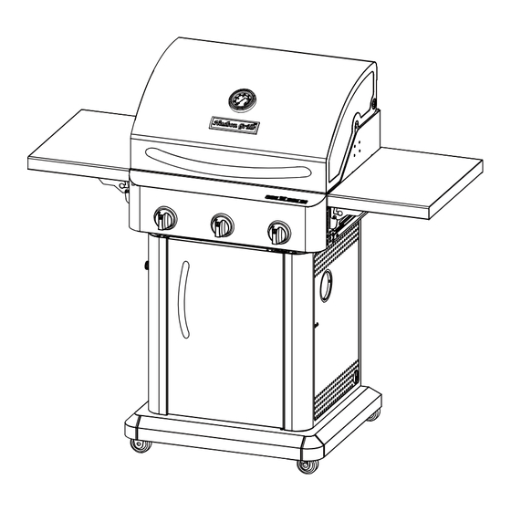
3-BURNER 304 STAINLESS STEEL GAS GRILL
ASSEMBLY AND CARE INSTRUCTIONS
WARNING
Improper installation, adjustment,
alteration, service or maintenance
can cause injury or property
damage.
Read the installation, operation
and maintenance instructions
thoroughly before installing or
servicing this equipment.
DANGER
Failure to follow these
instructions could result in fire
or explosion that could cause
property damage, personal injury
or death.
DANGER
DO NOT use gas grill for indoor
cooking or heating. TOXIC fumes
can accumulate and cause
asphyxiation. DO NOT use in or on
boats or recreational vehicles.
WARNING
FOR YOUR SAFETY
For Outdoor Use Only
(Outside any enclosure)
IMPORTANT:
RETAIN FOR FUTURE REFERENCE: READ CAREFULLY.
FOR CUSTOMER SERVICE:
Please E-mail: Service@fjchengyi.com.
1
ITM. / ART.
239418 (U.K)
ITM. / ART.
555820 (ICELAND)
MODEL NO.
U.K PART NO.
RT2417S-UK
ICELAND PART NO. RT2417S-IS
RT2417S
Advertisement
Table of Contents

Summary of Contents for Hudson RT2417S
- Page 1 MODEL NO. RT2417S Improper installation, adjustment, U.K PART NO. RT2417S-UK alteration, service or maintenance ICELAND PART NO. RT2417S-IS can cause injury or property damage. Read the installation, operation and maintenance instructions thoroughly before installing or ...
-
Page 2: Grill Operation
Grill Operation 1-2-3 Before Grilling Step 1 Keep your grill a safe distance away from your property. Step 2 Always perform a Leak Test on all connections and hoses. Step 3 Keep children away from the grill. During Grilling (To avoid tripping safety valves, please follow these instructions carefully!) Step 1 First open lid and turn gas tank on slowly. -
Page 3: Table Of Contents
Table of Contents For Your Safety............3 Safe Locations for Use of This Outdoor Grill . - Page 4 WARNING This grill is for outside use only. It should not be used in a building, garage or any other enclosed area. Read the instructions before using the appliance. The use of alcohol, prescription or non-prescription drugs may impair an individual’s ability to properly assemble or safely operate this appliance.
-
Page 5: Safe Locations For Use Of This Outdoor Grill
Safe Locations for Use of This Outdoor Grill CAUTION Never use this outdoor grill inside any building, garage, shed or breezeway, or inside any boat, trailer or recreational vehicle to prevent a possible fire and to prevent the possibility of carbon monoxide poisoning or asphyxiation. -
Page 6: General Information
GENERAL INFORMATION A propane or butane gas cylinder is required for operation. This gas grill is NOT intended for commercial use. Don’t obstruct the ventilation opening of the cylinder enclosure. Gas Category I3+(28-30/37) I3B/P(30) G30 Butane,G31 Propane or G30 Butane at 28~30 mbar Gas and Supply Pressure their mixtures at 28~30 mbar... -
Page 7: Package Contents
PACKAGE CONTENTS ... -
Page 8: Hardware Contents
PACKAGE CONTENTS Part Description Quantity Part Description Quantity Burner Box Drip Tray Support Heat Tent Rear Panel Main Grid Right Panel Warming Rack Drip Tray Right Side Shelf Bottom Panel Bracket Locking Caster ... -
Page 9: Assembly Instructions
Assembly Instructions UNPACKING After removing all parts and hardware pack from the top of the shipping box, and when the only part showing is the grill head, use a box cutting knife to slice down the sides of the box. Be careful of staples along shipping box edges. - Page 10 3. Attach the left panel (J) and right panel (N) to the bottom panel (P). For both the left and right panels, there are three screws for the rear panel (L) and four for the bottom panel. Insert the four bottom panel screws first. Hardware Used 3/16-24 x 1/2 in.
- Page 11 5. Attach the front beam (K) to the left panel and the right panel with 2 screws (AA) on each side as shown. Hardware Used 3/16-24 x 1/2 in. Screw 6. Attach the drip tray support (L) to the front beam and rear panel with 4 screws (AA) as shown.
- Page 12 8. For the door (S), insert bottom hinge pin into hole on bottom panel. Push top hinge pin in the corner of the door to insert into hole in top corner of the right panel. Then, put the drip tray (O) onto the drip tray support. 9.
- Page 13 10. Attach the left side shelf bracket (H) to the left of the burner box (A) and the right side shelf bracket (E) to the right of the burner box with 2 screws (AA) on each bracket. Hardware Used 3/16-24 x 1/2 in. Screw Follow steps 11 - 13 for installing or removing the side shelves (G and F).
- Page 14 12. To fold up the shelves: Make sure the screws are in the slot as shown, then slowly rotate the side shelf up. When folding up to level position, press down the hinge area to lock the shelf. Adjust the side shelves to align it with the control box.
- Page 15 14. Plug the main burner igniter wires into the sockets in the igniter. Igniter wire 15. Place the heat tents (B), main grids(C) and warming rack (D) into the burner box (A). Remove the battery cap on the igniter (M) and insert a AA battery (BB) with the positive end facing outward.
- Page 16 16. Open the door of cart. Take the regulator head out of the cart through the hole of the right side panel of the cart. Connect LP tank with the regulator, Please note that the LP tank must be placed outside of the cart. It is forbidden to place the tank into the cart.
-
Page 17: Operating Your Grill
Fully Assembled View Operating Your Grill CAUTION Use only the regulator provided. If a replacement is necessary, call our customer service center. The use of unauthorized parts can create an unsafe condition and environment. -
Page 18: Connecting & Disconnecting Gas Cylinder
DANGER A fire causing death or serious injury may occur if the following is not followed exactly: Never store or use gasoline or other volatile substances in the vicinity of this grill. Never store a spare propane or butane cylinder in the vicinity of this grill, or in the vicinity of another potential heat source. -
Page 19: Checking For Leaks
(9).The gas cylinder must always be used in the upright position. Whenever used outdoors, the A310/A300 must be suitably protected against rain. ‐ Never look for leaks using a flame, just use a soapy-water solution. ‐ In case of any difficulties or problems. Shut off the gas supply and contact your dealer immediately. ‐... -
Page 20: Lighting Your Grill
Lighting Your Grill DANGER Failure to open lid while igniting the grill’s burners or not waiting five minutes to allow gas to clear if the grill does not light, may result in an explosion, which could cause serious bodily injury or death . ... -
Page 21: Excess Flow Safety Valve Reset Procedure
Flare-Ups “Flare-ups” sometimes occur when food drippings fall onto the hot heat distribution plate or burners and ignite. Some flaring is normal and desirable as it helps impart the unique flavors associated with grilled foods. Controlling the intensity of the flare-ups is necessary, however, in order to avoid burned or unevenly cooked foods and to prevent the possibility of accidental fire. -
Page 22: Care And Maintenance
WARNING The cylinder valve always has to be in the horizontal position, to ensure that only the propane vapor is withdrawn. The hose is prohibited to exceed 1.5 m/ 59.05 in. 580mm/ 22.83 in/ 22.83 po ... - Page 23 4. Cleaning the Burner Assembly Follow these instructions to clean and/or replace parts of burner assembly or if you have trouble igniting grill. 4.1 Turn gas off at control knobs and LP cylinder. 4.2 Remove cooking grates and heat diffusers. 4.3 Remove R pins from rear of burners.
-
Page 24: Troubleshooting
TROUBLESHOOTING Problem Possible Cause Corrective Action 1. The ignition wire came off the 1. Reconnect the ignition wire to the electrical igniter. electrical igniter. 2. Loosen the ignition pin and adjust the distance, 2. The distance between the ignition pin then fasten it again. -
Page 25: Warranty Program
GRILL LIMITED WARRANTY WITH PROOF OF SALE, the following warranty coverage applies when this appliance is correctly installed, operated and Warranty Program maintained according to all supplied instructions. ONE YEAR Overall Warranty: From the date of sale this appliance is warranted against defects in material or workmanship. A defective appliance will receive free repair or replacement at option of seller. -
Page 26: Illustrated Parts List
Illustrated Parts List S2 12 S3 ... - Page 27 Key Qty Description Manufacturer Part # HEAT TENT RT2417S-UK-2003 COOKING GRID RT2417S-UK-2010 WARMING RACK RT2417S-UK-2020 TEMPERATURE GAUGE RC3218-00-8025 TEMPERATURE GAUGE BEZEL RC3218-00-4001 TEMPERATURE GAUGE SLEEVE RC3218-00-4009 HOOD RT2417S-UK-4000 RUBBER PLUG 3219B-8083 ...
- Page 28 If you have any questions about our products or warranty, please please E-mail: Service@fjchengyi.com. Manufactured by: Fujian Changtai Chengyi Industry CO., Ltd. Xingtai Industrial District, Changtai , Zhangzhou, Fujian, China Imported by: Distributed by: Costco Wholesale UK Ltd / Costco Wholesale Iceland ehf.
Need help?
Do you have a question about the RT2417S and is the answer not in the manual?
Questions and answers