Table of Contents
Advertisement
Quick Links
Advertisement
Table of Contents

Related Manuals for Cambium PTP 800 Series

Summary of Contents for Cambium PTP 800 Series
-
Page 1: User Guide
Cambium PTP 800 Series User Guide System Release 800-06-02... - Page 2 Cambium does not assume any liability arising out of the application or use of any product, software, or circuit described herein; neither does it convey license under its patent rights or the rights of others.
-
Page 3: Important Safety Information
PTP 800 Series User Guide Important safety information This section describes important safety guidelines that must be observed by personnel installing or operating PTP 800 equipment. Warning To prevent loss of life or physical injury, observe the safety guidelines in this section. -
Page 4: Electrical Safety
Important safety information Electrical safety The power cable connections must meet International Electrotechnical Commission (IEC) safety standards. Always power down and unplug the equipment before servicing. When using alternative DC supplies, such as battery-backed DC power source, the supply must be SELV rated. -
Page 5: Table Of Contents
PTP 800 Series User Guide Contents Important safety information ......................... I About This User Guide .......................... 1 General information ..........................2 Version information ........................2 Contacting Cambium Networks ....................2 Problems and warranty ........................4 Security advice ............................6 Warnings, cautions, and notes ......................7 Warnings ............................ - Page 6 Contents IRFU description ........................1-19 Transceivers ..........................1-20 Branching unit (BU) ........................1-20 IRFU frequency bands....................... 1-21 IRFU interfaces .......................... 1-21 Further reading on the IRFU ..................... 1-22 Antennas and couplers ........................1-23 Antennas ............................ 1-23 Remote Mounting Kit (RMK) ....................1-25 Coupler mounting kits ......................
- Page 7 PTP 800 Series User Guide Web server ..........................1-49 Installation wizard ........................1-51 Configuration pages ........................1-51 RADIUS authentication ......................1-51 Email alerts ..........................1-52 SNMP............................1-53 Simple Network Time Protocol (SNTP) ................... 1-54 SNMPv3 security ........................1-54 System logging (syslog) ......................1-57 AES license ..........................
- Page 8 Contents The need for power surge protection ..................2-7 Standards ............................. 2-7 Lightning protection zones ......................2-8 General protection requirements ....................2-9 Protection requirements for a mast or tower installation ............. 2-11 Protection requirements for the ODU on a high rise building ..........2-13 Protection requirements for the IRFU ..................
- Page 9 Ordering network connection components ................2-118 Ordering capacity upgrades and AES capability ..............2-119 Chapter 3: Legal information ......................3-1 Cambium Networks end user license agreement ................3-2 Acceptance of this agreement ....................3-2 Definitions ............................ 3-2 Grant of license ........................... 3-2 Conditions of use ........................
- Page 10 Contents Entire agreement ......................... 3-7 Third party software ........................3-7 Hardware warranty .......................... 3-18 Limit of liability ..........................3-19 Chapter 4: Reference information ....................4-1 Equipment specifications ........................4-2 CMU specifications ........................4-2 ODU specifications ........................4-5 IRFU specifications ........................4-9 Flexible waveguide specifications ...................
- Page 11 PTP 800 Series User Guide Grounding and lightning protection requirements ..............5-2 Preparing personnel ........................5-2 Preparing inventory ........................5-3 Designating primary and secondary units ................5-3 Installing antennas and ODUs ......................5-4 Mounting the antenna ........................ 5-5 Connecting the waveguide to the antenna ................5-6 Connecting the ODU to the antenna ..................
- Page 12 Contents Grounding the IRFU ........................5-75 Assembling the DC connector ....................5-76 Connecting power to the IRFU transceiver ................5-81 Replacing IRFU components ......................5-84 Locating IRFU components ...................... 5-84 Replacing a transceiver......................5-85 Replacing a BU .......................... 5-88 Replacing filters ......................... 5-90 Replacing a fan assembly ......................
- Page 13 PTP 800 Series User Guide Configuring the management PC ....................6-5 Updating the ARP table ......................6-8 Connecting to the PC and powering up ..................6-9 Using the web interface ........................6-10 Logging into the web interface ....................6-10 Layout of the web interface ...................... 6-11 Using the menu options ......................
- Page 14 Contents Configuring web-based management attributes ..............6-95 Configuring QoS ..........................6-97 Configuring QoS ........................6-97 Configuring for FIPS 140-2 applications ..................6-100 Prerequisites for FIPS 140-2 configuration ................6-100 Configuration procedures for FIPS 140-2 ................6-101 Checking that the unit is in FIPS 140-2 secure mode ............6-101 HTTPS key size warning ......................
- Page 15 Entering a license key ....................... 7-77 Starting the full capacity trial ....................7-79 Upgrading system software ......................7-80 Checking the installed software version ................. 7-80 Obtaining software images from Cambium ................7-81 Upgrading to a new software version ..................7-81 Chapter 8: Troubleshooting ......................8-1 Connecting to the web management interface ................
- Page 16 Contents Check the DC supply to the CMU ....................8-2 Check the CMU status indicator ....................8-3 CMU out of service ........................8-4 Check the Management port Ethernet connection ..............8-4 Check the copper Data port Ethernet connection ..............8-5 Check the fiber Data port Ethernet connection ................
-
Page 17: About This User Guide
PTP 800 Series User Guide About This User Guide This guide describes the planning, installation and operation of the Cambium PTP 800. It is intended for use by the system designer, system installer and the system administrator. Users of this guide should have knowledge of the following areas: •... -
Page 18: General Information
System Release 800-05-01 004v000 Oct 2012 System Release 800-05-02 005v000 Oct 2013 System Release 800-06-00 006v000 Oct 2013 System Release 800-06-01 Contacting Cambium Networks Support website: http://www.cambiumnetworks.com/support Main website: http://www.cambiumnetworks.com Sales enquiries: solutions@cambiumnetworks.com Support enquiries: support@cambiumnetworks.com Telephone number list: http://www.cambiumnetworks.com/support/contact-support... -
Page 19: Cross References
It is recommended that all personnel engaged in such activities be properly trained. Cambium disclaims all liability whatsoever, implied or express, for any risk of damage, loss or reduction in system performance arising directly or indirectly out of the failure of the customer, or anyone acting on the customer's behalf, to abide by the instructions, system parameters, or recommendations made in this document. -
Page 20: Problems And Warranty
Cambium shall within this time, at its own option, either repair or replace the defective product within thirty (30) days of receipt of the defective product. Repaired or replaced product will be subject to the original warranty period but not less than thirty (30) days. - Page 21 PTP 800 Series User Guide Problems and warranty Caution Portions of Cambium equipment may be damaged from exposure to electrostatic discharge. Use precautions to prevent damage. phn-2513_007v000 (March 2014)
-
Page 22: Security Advice
About This User Guide Security advice Cambium Networks systems and equipment provide security parameters that can be configured by the operator based on their particular operating environment. Cambium recommends setting and using these parameters following industry recognized security practices. Security aspects to be considered are protecting the confidentiality, integrity, and availability of information and assets. -
Page 23: Warnings, Cautions, And Notes
Warnings, cautions, and notes Warnings, cautions, and notes The following describes how warnings and cautions are used in this document and in all documents of the Cambium Networks document set. Warnings Warnings precede instructions that contain potentially hazardous situations. Warnings are used to alert the reader to possible hazards that could cause loss of life or physical injury. -
Page 24: Caring For The Environment
EU countries. Disposal of Cambium equipment European Union (EU) Directive 2002/96/EC Waste Electrical and Electronic Equipment (WEEE) Do not dispose of Cambium equipment in landfill sites. For disposal instructions, refer to http://www.cambiumnetworks.com/support Disposal of surplus packaging Do not dispose of surplus packaging in landfill sites. In the EU, it is the individual recipient’s responsibility to ensure that packaging materials are collected and recycled according to the requirements of EU environmental law. -
Page 25: Licensing Requirements
United States of America This device has been verified by Cambium Networks as being in compliance with the requirements of the rules of the Federal Communications Commission (FCC), 47 C.F.R. Part 101, and may not be operated without a station license. -
Page 27: Chapter 1: Product Description
PTP 800 Series User Guide Chapter 1: Product description This chapter provides a high level description of the PTP 800 product. It describes in general terms the function of the product, the main product variants and typical deployment. It also describes the main hardware components. -
Page 28: Overview
Chapter 1: Product description Overview Cambium PTP 800 Licensed Ethernet Microwave products are designed for Ethernet bridging at up to 368 Mbps over licensed point-to-point microwave links in selected licensed bands from 6 GHz to 38 GHz. The products offer exceptional cost efficiency and scalability. -
Page 29: Supported Bands And Frequencies
PTP 800 Series User Guide Overview Supported bands and frequencies The PTP 800 ODU platform supports the licensed bands and frequencies listed in Table 1 (ODU-A) Table 2 (ODU-B). The PTP 800 IRFU platform supports the licensed bands and frequencies listed... -
Page 30: Typical Users And Applications
Overview Chapter 1: Product description Table 3 PTP 800 licensed bands and frequencies (IRFU platform) Licensed band Regions Frequency coverage Lower 6 GHz FCC, IC 5.925 – 6.425 GHz Upper 6 GHz 6.525 – 6.875 GHz 7 GHz 6.875 – 7.125 GHz 11 GHz 10.70 –... -
Page 31: System Components
PTP 800 Series User Guide Overview System components The main components of the PTP 800 are shown in Figure 1 (ODU platform) and Figure 2 (IRFU platform). Figure 1 Typical PTP 800 deployment (ODU platform) Figure 2 Typical PTP 800 deployment (IRFU platform) -
Page 32: Supported Link Types
• Antennas and couplers: Cambium supplies high performance, low profile antennas for PTP 800 frequency bands in sizes from 0.3 m (1 ft) to 3.7 m (12 ft). These can be mounted directly to the ODUs, or remotely via waveguide. - Page 33 PTP 800 Series User Guide Overview • 1+1 Hot Standby (1+1 HSB): A 1+1 HSB link provides protection against single point equipment failure. This is achieved by the deployment of either two ODUs for outdoor deployments or a 1+1 capable IRFU for indoor deployments at each end, with two CMUs installed at each end. A 1+1 HSB link can also be configured to support Receive Spatial Diversity (Rx SD);...
-
Page 34: Compact Modem Unit (Cmu)
Compact Modem Unit (CMU) Chapter 1: Product description Compact Modem Unit (CMU) This section describes the PTP 800 CMU and its interfaces. CMU description The PTP 800 CMU (Figure 3) is mounted indoors and provides the Ethernet interface to the network. -
Page 35: Cmu Interfaces
PTP 800 Series User Guide Compact Modem Unit (CMU) CMU interfaces The CMU front panel interfaces are illustrated in Figure 4 and described in Table 4. The CMU front panel indicator LEDs and their states are described in Table Figure 4 CMU front panel... - Page 36 Compact Modem Unit (CMU) Chapter 1: Product description Interface Function Recovery This switch is used to start the CMU in recovery mode. Recovery mode provides a means to recover from serious configuration errors including lost or forgotten passwords and unknown IP addresses. For more information see Recovery mode on page 1-60.
- Page 37 PTP 800 Series User Guide Compact Modem Unit (CMU) Table 5 CMU LED states Indicator State Description Green steady RFU ready for use and transmitting Green slow blink RFU available for use but muted, or RFU incompatible with radio license configuration...
-
Page 38: Further Reading On The Cmu
• Ordering CMUs on page 2-73 describes how to order CMUs for the link and specifies the Cambium part number of the CMU kit. • CMU specifications on page contains specifications of the CMU, such as dimensions, weight and environmental requirements. -
Page 39: Outdoor Unit (Odu)
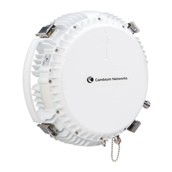
PTP 800 Series User Guide Outdoor Unit (ODU) Outdoor Unit (ODU) This section describes the PTP 800 ODU and its interfaces. ODU description The ODU is a Radio Frequency Unit (RFU) which provides the necessary frequency conversion and amplification of signals which pass between the CMU and antenna. -
Page 40: Odu Interfaces
Outdoor Unit (ODU) Chapter 1: Product description For more information about the capabilities and availability of ODU-A and ODU-B, refer to Ordering ODUs on page 2-87. ODU interfaces The ODU interfaces are illustrated in: Figure Figure Figure Figure 8 Figure 9. - Page 41 PTP 800 Series User Guide Outdoor Unit (ODU) Figure 6 ODU-B front view 1 – Waveguide polarization arrow. 2 – Spring loaded catches. 4 – Ground connector. 5 – RSSI connector. 6 – CMU connector. phn-2513_007v000 (March 2014) 1-15...
- Page 42 Outdoor Unit (ODU) Chapter 1: Product description Figure 7 ODU rear view 3 – Waveguide interface. phn-2513_007v000 (March 2014) 1-16...
- Page 43 PTP 800 Series User Guide Outdoor Unit (ODU) Figure 8 ODU-A side view 4 – Ground connector. 5 – RSSI connector. 6 – CMU connector. Figure 9 ODU-B side view 4 – Ground connector. 5 – RSSI connector. 6 – CMU connector.
-
Page 44: Further Reading On The Odu
These four spring loaded latches are used to fasten the ODU to the antenna, Remote Mounting Kit (RMK) or coupler. Waveguide interface This connects to a Cambium direct mount antenna, an ODU coupler kit, or an RMK. Ground connector This is used to ground the ODU to the top LPU. -
Page 45: Indoor Radio Frequency Unit (Irfu)
PTP 800 Series User Guide Indoor Radio Frequency Unit (IRFU) Indoor Radio Frequency Unit (IRFU) This section describes the PTP 800 IRFU and its interfaces. IRFU description The PTP 800 IRFU (Figure 10) can be chosen as an alternative to the ODU in cases where an all indoor solution is required. -
Page 46: Transceivers
The result is a fixed IF signal which is passed to the CMU for demodulation. Each transceiver is powered via its own dedicated power socket. Cambium Networks do not provide the power supply, but they do provide the power connector. For power supply... -
Page 47: Irfu Frequency Bands
PTP 800 Series User Guide Indoor Radio Frequency Unit (IRFU) IRFU frequency bands IRFUs are available at 6 GHz and 11 GHz. The supported licensed bands and frequencies are listed Table 3. Although the transceivers are designed to cover the entire frequency range of a given band, the BU is factory tuned for a specific transmit frequency and a specific receive frequency. -
Page 48: Further Reading On The Irfu
• Ordering IRFUs and accessories on page 2-111 lists the IRFUs, IRFU components, waveguides, antennas and antenna accessories for IRFU deployments, with Cambium part numbers. • IRFU specifications on page contains specifications of the IRFU, such as dimensions, weight, electrical and environmental requirements. -
Page 49: Antennas And Couplers
Antennas A typical antenna is shown in Figure Figure 12 Typical PTP 800 antenna with ODU (Cambium direct mount interface) Antenna diameter In each band, the antennas are provided in a number of diameters, the larger the diameter, the greater the gain. - Page 50 Antennas and couplers Chapter 1: Product description Figure 13 Direct mount mechanical interface Figure 14 ODU clipped onto direct mount mechanical interface Figure 15 Remote mount antenna waveguide interface phn-2513_007v000 (March 2014) 1-24...
-
Page 51: Remote Mounting Kit (Rmk)
PTP 800 Series User Guide Antennas and couplers Antenna polarization Antennas can be provided as single-polar or dual-polar: • Single-polar : A single-polar antenna provides a single interface to the RFU. The antennas are normally supplied with vertical polarization. For horizontal polarization, the antennas can be modified by the user using the instructions provided. -
Page 52: Coupler Mounting Kits
Antennas and couplers Chapter 1: Product description Figure 16 RMK showing the ODU interface Figure 17 RMK showing the waveguide interface Coupler mounting kits Note Applies to ODU deployments only. The signals from two ODUs can be coupled to a single antenna. The ODUs mount directly to the coupler (Figure 18) which then provides an interface to the antenna which is identical to that of an... - Page 53 PTP 800 Series User Guide Antennas and couplers • Symmetric coupler: The symmetric coupler splits the power evenly between the two ODUs. A nominal 3 dB is lost in each arm of the coupler. Symmetric couplers are required in 2+0 Co- Polar links.
-
Page 54: Direct Mount Dual-Polar Antennas
2-75. However, if a previously purchased antenna is to be upgraded to support a 2+0 cross-polar direct mount configuration, Cambium can supply separate Orthogonal Mounting Kits (OMKs), as listed in Ordering OMKs on page 2-111. The OMK can only be fitted to an antenna that is in the same band, for example, a 6 GHz antenna can only accept a 6 GHz OMK. -
Page 55: Further Reading On Antennas And Couplers
Cambium part numbers. • Ordering RMKs and waveguides on page 2-106 lists the RMKs, waveguides, hangers and transitions required for PTP 800 installations, with Cambium part numbers. • Ordering coupler mounting kits on page 2-109 lists the couplers required for PTP 800 installations, with Cambium part numbers. -
Page 56: Cabling And Lightning Protection
Caution The PTP 800 Series is not designed to survive direct lightning strikes. For this reason the antenna and ODU should not be installed at the highest point in a localized area. - Page 57 PTP 800 Series User Guide Cabling and lightning protection Figure 21 Cable grounding kit for 1/4 inch and 3/8 inch cable Lightning protection units (LPUs) The PTP 800 LPU end kit (Figure 22) is required for IF cables. One LPU is installed next to the ODU and the other is installed near the building entry point.
-
Page 58: Further Reading On Cabling And Lightning Protection
Cabling and lightning protection Chapter 1: Product description Further reading on cabling and lightning protection For more information on cabling and lightning protection, refer to the following: • Maximum IF cable length on page gives the maximum permitted lengths of IF cables in PTP 800 installations. -
Page 59: Wireless Operation
PTP 800 Series User Guide Wireless operation Wireless operation This section describes how the PTP 800 wireless link is operated, including modulation modes, power control and security. Channel separation The PTP 800 wireless link supports the following channel separations: •... -
Page 60: Modulation Modes
Wireless operation Chapter 1: Product description The available selection of channel bandwidths varies depending on band and region. Modulation modes The PTP 800 wireless link operates using single carrier modulation with the following fixed modulation modes: • QPSK • 8PSK •... -
Page 61: Automatic Transmitter Power Control (Atpc)
PTP 800 Series User Guide Wireless operation Automatic transmitter power control (ATPC) PTP 800 provides closed-loop ATPC. ATPC avoids overload of the receivers in links with low link loss by automatically adjusting transmitter power. The ATPC threshold is –40 dBm received power. -
Page 62: Maximum Transmit Power
Wireless operation Chapter 1: Product description Maximum transmit power Maximum transmit power is the maximum power that the PTP 800 is permitted to generate at the waveguide interface assuming that ATPC is disabled, or the link loss is high enough such that ATPC is not activated. - Page 63 PTP 800 Series User Guide Wireless operation • Monitoring performance on page 7-57 describes how to manage the performance of a PTP 800 link. phn-2513_007v000 (March 2014) 1-37...
-
Page 64: Ethernet Bridging
Customer network Transparent Ethernet service The PTP 800 Series provides an Ethernet service between the data port at a local CMU and the data port at an associated remote CMU. The Ethernet service is based on conventional layer two transparent bridging, and is equivalent to the Ethernet Private Line (EPL) service defined by the Metro Ethernet Forum (MEF). -
Page 65: Management Network
Ethernet bridging Quality of Service for bridged Ethernet traffic The PTP 800 Series supports eight traffic queues for Ethernet frames waiting for transmission over the wireless link. Ethernet frames are classified by inspection of the Ethernet destination address, the Ethernet priority code point in the outermost VLAN tag, the Differentiated Services Code Point (DSCP) in an IPv4 or IPv6 header, or the Traffic Class in an MPLS header. - Page 66 Ethernet bridging Chapter 1: Product description Out-of-band management PTP 800 supports an end-to-end out-of-band management mode in which the management agent can be reached from the management port at the local CMU, and (assuming that the wireless link is established) the management port at the remote CMU. This management mode allows communication from the CMU management port to Ethernet end stations reached through the remote CMU, supporting construction of an extended management network that is isolated from the customer network.
-
Page 67: Protocol Model
Wireless link down alert The PTP 800 Series can be configured to alert a loss of link to the connected network equipment. It does this by means of a brief disconnection of the copper data port or fiber data port. When the PTP 800 Series is configured for out-of-band operation, it also briefly disconnects the management port. - Page 68 Ethernet bridging Chapter 1: Product description Frames are transmitted at the Wireless port over a proprietary point-to-point circuit-mode link layer between ends of the PTP 800 link. For a single CMU configuration or the active CMU in a 1+1 HSB configuration, Ethernet frames received at the data or management ports, or generated internally within the management agent, are encapsulated within a lightweight MAC layer for transmission over the wireless link.
- Page 69 PTP 800 Series User Guide Ethernet bridging Figure 24 Forwarding behavior in out-of-band management mode Figure 25 Forwarding behavior in in-band mode Forwarding behavior for 1+1 HSB links Forwarding behavior for the active CMU is as for a non-protected link.
- Page 70 Ethernet bridging Chapter 1: Product description Figure 26 Inactive unit frame forwarding – out-of-band management Figure 27 Inactive unit frame forwarding – in-band management Protocol layers Protocol layers involved in bridging between Ethernet and wireless interfaces are shown in Figure 28.
- Page 71 PTP 800 Series User Guide Ethernet bridging Figure 28 Protocol layers between Ethernet and wireless interfaces Figure 29 Protocol layers between external interfaces and the management agent phn-2513_007v000 (March 2014) 1-45...
-
Page 72: Further Reading On Ethernet Bridging
Ethernet bridging Chapter 1: Product description Further reading on Ethernet bridging For more information on Ethernet bridging, refer to the following: • Data network planning on page 2-18 describes factors to be considered when planning PTP 800 data networks. • Data network specifications on page 4-74 contains specifications of the PTP 800 Ethernet interfaces. -
Page 73: System Management
PTP 800 Series User Guide System management System management This section introduces the PTP 800 management system, including the web interface, installation, configuration, alerts and upgrades. Management agent PTP 800 equipment is managed through an embedded management agent. Management workstations, network management systems or PCs can be connected to this agent using an in- band mode, or a choice of two out-of-band modes. -
Page 74: Ipv6
System management Chapter 1: Product description IPv6 The PTP 800 management agent supports the following IPv6 features: Neighbor discovery PTP 800 supports neighbor discovery for IPv6 as specified in RFC 4861 including: • Neighbor un-reachability detection (NUD), • Sending and receiving of neighbor solicitation (NS) and neighbor advertisement (NA) messages, •... -
Page 75: Web Server
PTP 800 Series User Guide System management DHCPv6 PTP 800 does not support address assignment using DHCPv6. The address of the management agent must be configured statically. Multicast listener discovery for IPv6 The PTP 800 management agent supports Multicast Listener Discovery version 1 (MLDv1) as specified in RFC 2710. - Page 76 Security planning on page Note The PTP 800 has no default public key certificate, and Cambium Networks is not able to generate private keys or public key certificates for specific network applications. Note PTP 800 supports a single public key certificate for HTTPS. This certificate must be based on an IPv4 or IPv6 address as the Common Name.
-
Page 77: Installation Wizard
PTP 800 Series User Guide System management SNMP control of passwords PTP 800 allows the role-based and identity-based passwords for the web-based interface to be updated using the proprietary SNMP MIB. This capability is controlled by the SNMP Control of Passwords, and is disabled by default. -
Page 78: Email Alerts
System management Chapter 1: Product description Remote authentication can be used in addition to local authentication, or can be used as a replacement for local authentication. If remote and local authentications are used together, PTP 800 checks log in attempts against locally stored user credentials before submitting a challenge and response for remote authentication. -
Page 79: Snmp
PTP 800 Series User Guide System management SNMP The management agent supports fault and performance management by means of an SNMP interface. The management agent is compatible with SNMP v1 and SNMP v2c, using the following MIBs: • PTP 800 enterprise MIB •... -
Page 80: Simple Network Time Protocol (Sntp)
System management Chapter 1: Product description • Wireless receive status • Licensed transmit capacity • Wireless receive mismatch • Data port Ethernet speed mismatch • Management port Ethernet speed mismatch SNMP notifications are described in Managing alarms and events on page 7-13. Simple Network Time Protocol (SNTP) The clock supplies accurate date and time information to the system. - Page 81 PTP 800 Series User Guide System management • MD5, AES, • SHA-1, AES. Use of AES privacy requires the AES upgrade described in AES license on page 1-58. The system will allow the creation of users configured with AES privacy protocol, regardless of license key.
- Page 82 System management Chapter 1: Product description The system creates the initial user and template users with localized authentication and privacy keys derived from the passphrase string 123456789. Authentication keys for the templates users are fixed and cannot be changed. Any or all of the template users can be deleted. The default user is created with a view of the entire MIB, requiring authentication for SET initial...
-
Page 83: System Logging (Syslog)
PTP 800 Series User Guide System management • The SNMP Engine ID Format is IPv4 Address or IPv6 Address and the IP Address has been changed. • The SNMP Engine ID Format is Text String and the text string has been changed. -
Page 84: Aes License
PTP 800 provides optional encryption using the AES. Encryption is not available in the standard system. AES upgrades are supplied as an access key purchased from a Cambium Point-to-Point distributor or solutions provider. The access key authorizes AES operation for one CMU. Two access keys are needed to operate AES on a link. -
Page 85: Login Information
There is no need to reboot the CMU, and the upgrade process does not involve a service interruption. Once applied, the capacity upgrade is bound to a single CMU and is not transferrable. For ordering details including Cambium part numbers, refer to Ordering capacity upgrades and AES capability on page 2-119. -
Page 86: Software Upgrade
The management agent supports application software upgrade using the web-based interface. PTP 800 software images are digitally signed, and the CMU will accept only images that contain a valid Cambium PTP digital signature. The CMU always requires a reboot to complete a software upgrade. -
Page 87: Further Reading On System Management
PTP 800 Series User Guide System management Recovery mode supports a single IPv4 interface, with IP address 169.254.1.1. Recovery mode does not support IPv6. Note If recovery mode has been entered either because of a checksum error or Short Power Cycle, by default the CMU will reboot with existing software and configuration following a 30 second wait. -
Page 88: 1+1 Hot Standby Link Protection
1+1 Hot Standby link protection Chapter 1: Product description 1+1 Hot Standby link protection This section is an overview of the concept, operation and interfaces of 1+1 HSB links. 1+1 HSB overview The 1+1 HSB feature provides an option for protecting against a single point equipment failure. It also enables maintenance to be carried out with insignificant impact on customer traffic. -
Page 89: 1+1 Hsb Link Antenna Options
PTP 800 Series User Guide 1+1 Hot Standby link protection Primary and secondary units At each end of the link, one CMU must be configured as a Primary unit, the other as a Secondary unit. The decision of whether the Primary or Secondary CMU becomes active is automatically controlled by the CMU application software. -
Page 90: Bridging In 1+1 Links
1+1 Hot Standby link protection Chapter 1: Product description Bridging in 1+1 links Only the active CMU forwards customer data from the wireless interface to the Ethernet switch. Also, when Out of Band Management is enabled, only the active CMU forwards management data received from the wireless interface to the Ethernet Switch. - Page 91 PTP 800 Series User Guide 1+1 Hot Standby link protection Receive Diversity Ethernet frames An important aspect of Receive Diversity is how the data received at the wireless interface of the Inactive CMU arrives at the Active CMU. This is achieved by the Inactive CMU encapsulating the received wireless data into Ethernet frames and sending the frames out on the Data port at a constant rate.
-
Page 92: Further Reading On 1+1 Hsb
1+1 Hot Standby link protection Chapter 1: Product description • The Fiber-Y configuration is useful in a network which requires a single Ethernet interface for customer traffic. In order to support Receiver Diversity in Fiber-Y configurations, the CMU copper data ports must also be connected to the same Ethernet Switch as the Fiber-Y interface. This is because the Fiber port of the Inactive CMU is necessarily disabled in Fiber-Y configurations. - Page 93 PTP 800 Series User Guide 1+1 Hot Standby link protection • Testing protection switchover on page 8-13 describes the tests to be performed if any problems are experienced with protection switchovers in a newly installed (or operational) 1+1 HSB link.
-
Page 94: Fips 140-2
FIPS 140-2 Chapter 1: Product description FIPS 140-2 This section describes the (optional) FIPS 140-2 cryptographic mode of operation. PTP 800 provides an optional secure cryptographic mode of operation validated to Level 1 of Federal Information Processing Standards Publication 140-2. FIPS 140-2 capability A PTP 800 unit is capable of operating in the FIPS 140-2 mode when all of the following are true: •... -
Page 95: Fips 140-2 Mode
PTP 800 Series User Guide FIPS 140-2 Indication of FIPS 140-2 capability The FIPS 140-2 capability is indicated by a distinctive symbol displayed at the top of the navigation bar in the web-based interface, as shown in Figure Figure 32 Indication of FIPS 140-2 capability... -
Page 96: Further Reading On Fips 140-2
FIPS 140-2 Chapter 1: Product description Indication of FIPS 140-2 mode The PTP 800 is operating in FIPS 140-2 mode when the FIPS 140-2 capability logo is displayed in the navigation bar and the FIPS Operational Mode Alarm is absent from the Home page. Exiting from the FIPS 140-2 operational mode A PTP 800 in FIPS 140-2 operational mode can be prepared to accept new security configuration by zeroizing CSPs. -
Page 97: Chapter 2: Planning Considerations
• Ordering components on page describes how to select components for a planned 2-73 PTP 800 link (as an alternative to PTP LINKPlanner). It specifies Cambium part numbers for PTP 800 components. phn-2513_007v000 (March 2014) -
Page 98: Link Planning
Link planning Chapter 2: Planning considerations Link planning When planning the link, follow the high level process described in this section. Take account of factors such as site selection, wind loading, cable length and power supply. Use PTP LINKPlanner as a tool to plan the link. Process The majority of the 6 to 38 GHz spectrum is licensed on a link by link basis. -
Page 99: Site Selection
Conduct a site survey to ensure that there are no other obstacles. Wind loading Select a site where the wind load will not be too high. For all the antennas supplied by Cambium, the maximum permitted wind velocities are: •... -
Page 100: Power Supply Considerations
Confirm that the planned site has a power supply that meets the following requirements: • The CMU requires either a mains power supply (with the AC to DC power supply convertor available from Cambium) or a -48 V dc power supply. • The IRFU (if deployed) requires a -48 V dc power supply. -
Page 101: Ptp Linkplanner
Link planning PTP LINKPlanner Use the Cambium PTP LINKPlanner to design PTP 800 links. This is a link planning and optimization tool designed for use with all PTP products. PTP LINKPlanner is free and available from the support web page (see Contacting Cambium Networks on page 2). - Page 102 Link planning Chapter 2: Planning considerations The PTP LINKPlanner also provides configuration and performance details as shown in Figure and Bill of Materials data as shown in Figure This is necessarily a brief introduction to the PTP LINKPlanner. Please download and evaluate this free software in further detail.
-
Page 103: Grounding And Lightning Protection
(typically caused by lightning) by conducting the surge current to ground via a separate preferential solid path. The actual degree of protection required depends on local conditions and applicable local regulations. Cambium recommends that PTP 800 installation is contracted to a professional installer. -
Page 104: Lightning Protection Zones
Grounding and lightning protection Chapter 2: Planning considerations Lightning protection zones Use the rolling sphere method (Figure 37) to determine where it is safe to mount equipment. An imaginary sphere, typically 50 meters in radius, is rolled over the structure. Where the sphere rests against the ground and a strike termination device (such as a finial or ground bar), consider the space under the sphere to be in the zone of protection (Zone B). -
Page 105: General Protection Requirements
PTP 800 Series User Guide Grounding and lightning protection General protection requirements Ensure that the PTP 800 installation meets the general protection requirements described in this section. Basic requirements Install the outdoor equipment, that is antenna and ODU (if deployed), in Zone B (see... - Page 106 Applies to ODU deployments only. Use LPUs and IF cables that meet the following requirements: • An LPU (Cambium part number WB3657) is installed within 600 mm (24 in) of the point at which the IF cable enters the building or equipment room. •...
-
Page 107: Protection Requirements For A Mast Or Tower Installation
PTP 800 Series User Guide Grounding and lightning protection Protection requirements for a mast or tower installation Note Applies to ODU deployments only. For equipment (ODU or antenna) mounted on a metal tower or mast, ensure that the installation meets the following requirements: •... - Page 108 Grounding and lightning protection Chapter 2: Planning considerations Mast or tower protection diagrams Figure 38 shows the protection requirements for an ODU mounted on a metal tower or mast. Figure 39 shows the protection requirements for a 1+1 HSB protected end. Figure 38 Grounding and lightning protection on mast or tower phn-2513_007v000 (March 2014) 2-12...
-
Page 109: Protection Requirements For The Odu On A High Rise Building
PTP 800 Series User Guide Grounding and lightning protection Figure 39 Grounding and lightning protection on mast or tower (protected end) Protection requirements for the ODU on a high rise building Note Applies to ODU deployments only. If the antenna or ODU is mounted on a high rise building, with cable entry at roof level... - Page 110 Grounding and lightning protection Chapter 2: Planning considerations • A grounding conductor is installed around the roof perimeter, to form the main roof perimeter lightning protection ring. • Air terminals are installed along the length of the main roof perimeter lightning protection ring typically every 6.1m (20ft).
- Page 111 PTP 800 Series User Guide Grounding and lightning protection Protection inside the building Inside multi-story or high rise buildings (Figure 41), ensure that the installation meets the following requirements: • The IF cable shield is bonded to the building grounding system at the entry point to the building.
- Page 112 Grounding and lightning protection Chapter 2: Planning considerations Figure 42 Grounding and lightning protection inside high building (protected end) phn-2513_007v000 (March 2014) 2-16...
-
Page 113: Protection Requirements For The Irfu
PTP 800 Series User Guide Grounding and lightning protection Protection requirements for the IRFU Note Applies to IRFU deployments only. Ensure that all IRFU installations meet the following requirements: • The CMU and IRFU are grounded at their chassis bonding points to the building grounding... -
Page 114: Data Network Planning
Data network planning Chapter 2: Planning considerations Data network planning When planning PTP 800 data networks, consider the factors described in this section. Management mode Decide how the PTP 800 will be managed. There are three modes of management: out-of-band local, out-of-band and in-band. -
Page 115: Vlan Membership
PTP 800 Series User Guide Data network planning VLAN membership Decide if the IP interface of the CMU management agent will be connected in a VLAN. If so, decide if this is a standard (IEEE 802.1Q) VLAN or provider bridged (IEEE 802.1ad) VLAN, and select the VID for this VLAN. - Page 116 Data network planning Chapter 2: Planning considerations Layer 2 control protocols Select the transmission queue for each of the recognized layer 2 control protocols (L2CP). These protocols are essential to correct operation of the Ethernet network, and are normally mapped to a high priority queue.
-
Page 117: Fast Ethernet Port Shutdown
PTP 800 Series User Guide Data network planning Out-of-band management When the wireless link is configured for out-of-band management, select an appropriate setting for the Management CIR attribute. A high CIR will provide greater capacity for management traffic, at the cost of allowing bursty management traffic to have a greater impact on capacity remaining for customer traffic. -
Page 118: Security Planning
Security planning Chapter 2: Planning considerations Security planning When planning PTP 800 links to operate in secure mode, follow the process described in this section. Planning for SNTP operation To prepare for SNTP operation: • Identify the time zone and daylight saving requirements that apply to the system. •... -
Page 119: Planning For Https/Tls Operation
PTP 800 Series User Guide Security planning Planning for HTTPS/TLS operation To prepare for HTTPS/TLS operation, obtain the cryptographic material listed in Table Table 8 HTTPS/TLS security material Item Description Quantity required Key of Keys An encryption key generated using a One per unit. -
Page 120: Planning For Fips 140-2 Operation
Security planning Chapter 2: Planning considerations Planning for FIPS 140-2 operation To prepare for FIPS 140-2 secure mode operation, generate the following cryptographic material using a FIPS-approved cryptographic generator: • Key of Keys • TLS Private Key and Public Certificates. FIPS 140-2 now recommends 2048 bit keys. •... -
Page 121: Planning For Snmpv3 Operation
PTP 800 Series User Guide Security planning Planning for SNMPv3 operation SNMP security mode Select one of the following SNMPv3 security modes: • Use MIB-based security management to tailor views and security levels appropriate for different types of user. MIB-based security management uses standard SNMPv3 MIBs to configure the user-based security model and the view-based access control model. - Page 122 Security planning Chapter 2: Planning considerations • • Select one of the following privacy protocols (if required): • • AES: This is only available to users who have purchased an appropriate license key. For authentication and privacy protocols, identify passphrases for each protocol for each SNMP user.
- Page 123 PTP 800 Series User Guide Security planning SNMPv3 default configuration (MIB-based) When SNMPv3 MIB-based Security Mode is enabled, the default configuration for the table is based on one initial user and four template users as listed in Table usmUserTable Table 10 Default SNMPv3 users...
-
Page 124: Planning For Radius Operation
Security planning Chapter 2: Planning considerations Planning for RADIUS operation Configure RADIUS where remote authentication is required for users of the web-based interface. Remote authentication has the following advantages: • Control of passwords can be centralized. • Management of user accounts can be more sophisticated For example, users can be prompted by email to change passwords at regular intervals. - Page 125 PTP 800 Series User Guide Security planning If the vendor-specific auth-role attribute is absent, but the standard service-type (Type 6) attribute is present, PTP 800 selects the role for the authenticated user according to service-type. The supported values of service-type are as follows: •...
-
Page 126: 1+0 Links
1+0 links Chapter 2: Planning considerations 1+0 links This section defines the concept of a 1+0 link. It also describes the supported radio hardware options and network configurations for 1+0 links. Concept of a 1+0 link A 1+0 link is the simplest link to deploy. There is no redundant equipment deployed and so costs are minimized. - Page 127 PTP 800 Series User Guide 1+0 links Figure 44 1+0 with ODU and direct mount phn-2513_007v000 (March 2014) 2-31...
- Page 128 1+0 links Chapter 2: Planning considerations Figure 45 1+0 with ODU and remote mount phn-2513_007v000 (March 2014) 2-32...
- Page 129 PTP 800 Series User Guide 1+0 links Figure 46 1+0 with IRFU phn-2513_007v000 (March 2014) 2-33...
-
Page 130: Network Configurations For 1+0
1+0 links Chapter 2: Planning considerations Network configurations for 1+0 Install the 1+0 network connections as shown in Figure 47. For out-of-band management, provide both Data port and Management port cables. For in-band management, provide Data port cables only. For part numbers, see Ordering network connection components on page 2-118. -
Page 131: 1+1 Hsb Links
PTP 800 Series User Guide 1+1 HSB links 1+1 HSB links This section defines the concepts of 1+1 Hot Standby (HSB) and 1+1 Hot Standby with Spatial Diversity (HSB SD). It also describes the supported radio hardware options and network configurations for 1+1 HSB and 1+1 HSB SD links. -
Page 132: Radio Hardware Options For 1+1 Hsb Links
1+1 HSB links Chapter 2: Planning considerations Spatial Diversity can significantly improve the availability of a link, particularly for long links. Regulations can recommend or even mandate that Spatial Diversity is deployed for links which are longer than a specific range. LINKPlanner calculates link availability for all link configurations and provides a very convenient way of seeing the effect of enabling Spatial Diversity. - Page 133 PTP 800 Series User Guide 1+1 HSB links Figure 48 1+1 HSB with ODUs and direct mount phn-2513_007v000 (March 2014) 2-37...
- Page 134 1+1 HSB links Chapter 2: Planning considerations Figure 49 1+1 HSB with ODUs and remote mount phn-2513_007v000 (March 2014) 2-38...
- Page 135 PTP 800 Series User Guide 1+1 HSB links Figure 50 1+1 HSB with IRFU phn-2513_007v000 (March 2014) 2-39...
- Page 136 1+1 HSB links Chapter 2: Planning considerations Figure 51 1+1 HSB SD with ODUs and direct mount phn-2513_007v000 (March 2014) 2-40...
- Page 137 PTP 800 Series User Guide 1+1 HSB links Figure 52 1+1 HSB SD with ODUs and remote mount phn-2513_007v000 (March 2014) 2-41...
- Page 138 1+1 HSB links Chapter 2: Planning considerations Figure 53 1+1 HSB SD with IRFU phn-2513_007v000 (March 2014) 2-42...
-
Page 139: Network Configurations For 1+1
PTP 800 Series User Guide 1+1 HSB links Network configurations for 1+1 1+1 HSB link management In a 1+1 HSB Link, each CMU is managed separately and must be assigned its own Internet address. Choosing Ethernet switches The Ethernet switch must react to a brief disconnection of an Ethernet port by flushing its... - Page 140 1+1 HSB links Chapter 2: Planning considerations The Fiber-Y arrangement can be a useful feature in complex networks, such as ring architectures, where there is a requirement for the link to provide a single interface at the Ethernet Switch. The Ethernet Switch must provide a single fiber port.
- Page 141 PTP 800 Series User Guide 1+1 HSB links Figure 55 Schematic of 1+1 out-of-band network connections (Fiber-Y) 1+1 HSB link with in-band management In Band management provides a single network which multiplexes customer data with management data. Please refer to...
-
Page 142: Planning For Receive Diversity
1+1 HSB links Chapter 2: Planning considerations Figure 56 Schematic of 1+1 in-band network connections Planning for Receive Diversity PTP 800 supports the Receive Diversity feature, which provides hitless protection against receiver faults. This feature can be enabled (at the CMU) in any of the supported 1+1 HSB configurations described in Radio hardware options for 1+1 HSB links on page 2-36. - Page 143 PTP 800 Series User Guide 1+1 HSB links • The Ethernet Switch must support the configuration of Virtual LANs using either 802.1Q or 802.1ad. Configuring a dedicated VLAN to bridge Receive Diversity Ethernet Frames from the Inactive CMU to the Active CMU prevents these frames from flooding the network.
- Page 144 1+1 HSB links Chapter 2: Planning considerations Table 12 Frame size and latency relationship in Rx SD links Maximum Customer Frame Size Latency increase with Receive (octets) Diversity enabled (µs) 1500 9600 In all cases, the minimum latency does not change hence jitter is increased. Link planning for Spatial Diversity SD can significantly improve the availability of a link, particularly for long links.
-
Page 145: 2+0 Links
PTP 800 Series User Guide 2+0 links 2+0 links This section defines the concepts of 2+0 links (2+0 Co-Polar and 2+0 Cross-Polar). It describes the supported radio hardware options and network configurations for 2+0 links. It also defines the required frequency separations for 2+0 links. -
Page 146: Radio Hardware Options For 2+0 Links
Select one of the following radio hardware options for a 2+0 Cross-Polar link: • 2+0 Cross-Polar with ODUs and direct mount (Figure • 2+0 Cross-Polar with ODUs and remote mount (Figure Note To upgrade any standard antenna to dual-polar direct mount, purchase an OMK from Cambium. phn-2513_007v000 (March 2014) 2-50... - Page 147 PTP 800 Series User Guide 2+0 links Figure 57 2+0 Co-Polar with ODUs and direct mount phn-2513_007v000 (March 2014) 2-51...
- Page 148 2+0 links Chapter 2: Planning considerations Figure 58 2+0 Co-Polar with ODUs and remote mount phn-2513_007v000 (March 2014) 2-52...
- Page 149 PTP 800 Series User Guide 2+0 links Figure 59 2+0 Co-Polar with IRFU phn-2513_007v000 (March 2014) 2-53...
- Page 150 2+0 links Chapter 2: Planning considerations Figure 60 2+0 Cross-Polar with ODUs and direct mount phn-2513_007v000 (March 2014) 2-54...
-
Page 151: Frequency Separation In 2+0 Links
PTP 800 Series User Guide 2+0 links Figure 61 2+0 Cross-Polar with ODUs and remote mount Frequency separation in 2+0 links 2+0 Co-Polar (ODU-based) For Co-Polar 2+0 ODU-based deployments the transmit and receive frequencies at a given end must meet the following requirements: •... - Page 152 2+0 links Chapter 2: Planning considerations Table 13 Frequency separation in 2+0 links Frequency Standard ODU T/R Spacing Maximum Minimum Separation Band Channel between transmit and Bandwidth receive frequencies for ODUs at same end of link (*1) Lower 6 GHz FCC, ETSI 252 MHz 30 MHz (*2)
- Page 153 PTP 800 Series User Guide 2+0 links Frequency Standard ODU T/R Spacing Maximum Minimum Separation Band Channel between transmit and Bandwidth receive frequencies for ODUs at same end of link (*1) 15 GHz Mexico 315 MHz 28 MHz 150 MHz...
- Page 154 2+0 links Chapter 2: Planning considerations • Link A Tx and Link B Rx must be separated by at least 150 MHz. • Link B Tx and Link A Rx must be separated by at least 150 MHz. (*2): In the 6 GHz bands, 2+0 is not supported with 60 MHz bandwidth. 2+0 Co-Polar (IRFU-based) In a 2+0 IRFU-based link, plan the four transmit frequencies to meet the following requirements: •...
- Page 155 PTP 800 Series User Guide 2+0 links • Link B Tx and Link A Rx must be separated by at least 70 MHz. • Link B Tx and Link B Rx must be separated by at least 70 MHz. 2+0 Cross-Polar (ODU-based)
- Page 156 2+0 links Chapter 2: Planning considerations Frequency Standard ODU T/R Maximum Minimum Separation Band Spacing Channel between transmit and receive Bandwidth frequencies for ODUs at same end of link (*1) 8 GHz ETSI 266 MHz 28 MHz 100 MHz 8 GHz ETSI 311 MHz 28 MHz...
-
Page 157: Network Configurations For 2+0
PTP 800 Series User Guide 2+0 links Frequency Standard ODU T/R Maximum Minimum Separation Band Spacing Channel between transmit and receive Bandwidth frequencies for ODUs at same end of link (*1) 23 GHz 1200 MHz 50 MHz 230 MHz 23 GHz... - Page 158 IRFU branching configurations Chapter 2: Planning considerations IRFU branching configurations Note Applies to IRFU deployments only. This section describes the available IRFU branching configurations and shows how to select the correct branching configuration for each link type (Table 17). Table 17 Selecting the correct IRFU branching configuration Link type IRFU branching configuration IRFU 1+0...
- Page 159 PTP 800 Series User Guide IRFU branching configurations IRFU 1+0 Used for: 1+0 links. This consists of a single transceiver with the BU providing a single waveguide interface (Figure 62 Figure 63). With this option, the right hand transceiver position is not populated.
-
Page 160: Irfu Branching Configurations
IRFU branching configurations Chapter 2: Planning considerations Figure 63 IRFU 1+0 internal configuration PA = Power Amplifier HPA = High Power Amplifier LNA = Low Noise Amplifier IRFU 1+0 Tx MHSB Ready Used for: 1+0 links, if a future upgrade to 1+1 HSB is anticipated. Available with equal or unequal transceiver coupling. - Page 161 PTP 800 Series User Guide IRFU branching configurations Figure 64 IRFU 1+0 Tx MHSB Ready Antenna port (at back) Transceiver Tx filter Rx filter with splitter (50 Ohm termination on unused port) RF switch phn-2513_007v000 (March 2014) 2-65...
-
Page 162: Irfu 1+1 Tx Mhsb
IRFU branching configurations Chapter 2: Planning considerations Figure 65 IRFU 1+0 Tx MHSB Ready internal configuration PA = Power Amplifier HPA = High Power Amplifier LNA = Low Noise Amplifier IRFU 1+1 Tx MHSB Used for: 1+1 HSB links. Available with equal or unequal transceiver coupling. This option consists of two transceivers with the BU providing a single waveguide interface for connection to an antenna (Figure 66... - Page 163 PTP 800 Series User Guide IRFU branching configurations Figure 66 IRFU 1+1 Tx MHSB front and back views Antenna port (at back) Transceiver A Tx filter Rx filter with splitter RF switch Transceiver B phn-2513_007v000 (March 2014) 2-67...
- Page 164 IRFU branching configurations Chapter 2: Planning considerations Figure 67 IRFU 1+1 Tx MHSB internal configuration PA = Power Amplifier HPA = High Power Amplifier LNA = Low Noise Amplifier phn-2513_007v000 (March 2014) 2-68...
-
Page 165: Irfu 1+1 Tx Mhsb / Rx Sd
PTP 800 Series User Guide IRFU branching configurations IRFU 1+1 Tx MHSB / Rx SD Used for: 1+1 HSB SD links. This option consists of two transceivers with the BU providing two waveguide interfaces (Figure 68 Figure 69). As well as providing MHSB operation in the event of single point equipment failure, it also provides Receive Spatial Diversity (Rx SD) by providing a second waveguide interface which connects to a diverse antenna. - Page 166 IRFU branching configurations Chapter 2: Planning considerations Main antenna port (at back) Transceiver A Tx filter Rx filter A RF switch Transceiver B Diversity antenna port (at back) Rx filter B Figure 69 IRFU 1+1 Tx MHSB / Rx SD internal configuration phn-2513_007v000 (March 2014) 2-70...
-
Page 167: Irfu 2 Coupled Transceiver
PTP 800 Series User Guide IRFU branching configurations PA = Power Amplifier HPA = High Power Amplifier LNA = Low Noise Amplifier IRFU 2 Coupled Transceiver Used for: 2+0 Co-Polar links. This option consists of two transceivers which couple together through filters and circulators to a... - Page 168 IRFU branching configurations Chapter 2: Planning considerations Antenna port (at back) Transceiver A Tx filter A Rx filter A Transceiver B Tx filter B Rx filter B Figure 71 IRFU 2 Coupled Transceiver internal configuration PA = Power Amplifier HPA = High Power Amplifier LNA = Low Noise Amplifier phn-2513_007v000 (March 2014) 2-72...
-
Page 169: Ordering Components
PTP 800 Series User Guide Ordering components Ordering components This section describes how to select components for a planned PTP 800 link. Ordering CMUs Determine the number of CMUs required per link, as follows: • 1+0 links: 2 CMUs. •... - Page 170 Ordering components Chapter 2: Planning considerations Item Cambium description, part number and notes Mains Lead (for AC to DC converter) “Mains Lead- US 3pin to C5 (PTP800 AC-DC PSU)”. Cambium part number WB3618. “Mains Lead- UK 3pin to C5 (PTP800 AC-DC PSU)”.
-
Page 171: Ordering Antennas
Not all antennas are supported for IRFU based installations. Use PTP LINKPlanner to confirm that the selected antenna is compatible with the required IRFU configuration. In the Interface column of these tables, “Direct” means Cambium direct mount and a flange size, for example “PDR70”, means remote mount. - Page 172 85009294004 3.7 m (12 ft) CPR137G 44.9 dBi 0.9° 245 kg (540 lb) (*1): Lower 6 GHz only (*2): Upper 6 GHz only Table 20 Antennas: 6 GHz dual-polarization Cambium number Diameter Interface Mid-band Vertical Weight gain beamwidth 85009302001 1.0 m (3 ft)
- Page 173 PTP 800 Series User Guide Ordering components Cambium number Diameter Interface Mid-band Vertical Weight gain beamwidth 85010092021 1.8 m (6 ft) PDR70 39 dBi 1.8° 62 kg (137 lb) N060080L001 (*2) 1.2 m (4 ft) CPR137G 34.4 dBi 3.0° 69 kg (152 lb) N060080L011 (*3) 1.2 m (4 ft)
- Page 174 55 kg (121 lb) 85010092025 1.8 m (6 ft) PDR84 40.6 dBi 1.5 ° 62 kg (137 lb) (*) The antenna includes an OMT. Table 23 Antennas: 11 GHz single-polarization Cambium number Diameter Interface Mid-band Vertical Weight gain beamwidth 85010089049 0.6 m (2 ft)
- Page 175 PTP 800 Series User Guide Ordering components Cambium number Diameter Interface Mid-band Vertical Weight gain beamwidth 85010091017 1.0 m (3 ft) PDR100 (*1) 38.4 dBi 2.0° 24 kg (53 lb) 85010091026 1.2 m (4 ft) PDR100 (*1) 40.4 dBi 1.5°...
- Page 176 Chapter 2: Planning considerations Note The 11 GHz waveguide interface antennas require an extra component, the 11 GHz tapered transition. This is supplied by Cambium (Table 60) and is required to convert between the antenna interface and the waveguide flange.
- Page 177 PTP 800 Series User Guide Ordering components Cambium Diameter Interface Mid- Vertical Weight number band beamwidth gain 85009305005 1.8 m (6 ft) Direct (*) 45.2 dBi 0.9° 85010092026 0.3 m (1 ft) PBR120 30.9 dBi 4.7° 7 kg (15 lb) 85010092056 0.6 m (2 ft)
- Page 178 Ordering components Chapter 2: Planning considerations Cambium Diameter Interface Mid- Vertical Weight number band beamwidth gain 85009306005 1.8 m (6 ft) Direct (*) 46.2 dBi 0.8° 85010092031 0.3 m (1 ft) PBR140 32.0 dBi 4.3° 7 kg (15 lb) 85010092057 0.6 m (2 ft)
- Page 179 PTP 800 Series User Guide Ordering components Cambium Diameter Interface Mid- Vertical Weight number band beamwidth gain 85009307005 1.8 m (6 ft) Direct (*) 47.6 dBi 0.7° 85010092006 0.3 m (1 ft) PBR220 34.2 dBi 3.3° 6 kg (13 lb) 85010092053 0.6 m (2 ft)
- Page 180 Ordering components Chapter 2: Planning considerations Cambium Diameter Interface Mid- Vertical Weight number band beam gain -width 85009308005 1.8 m (6 ft) Direct (*) 49.2 dBi 0.5° 85010092011 0.3 m (1 ft) PBR220 35.3 dBi 3.0° 6 kg (13 lb) 85010092054 0.6 m (2 ft)
- Page 181 PTP 800 Series User Guide Ordering components Table 35 Antennas: 28 GHz single-polarization Cambium Diameter Interface Mid- Vertical Weight number band beam- gain width 85010089064 0.3 m (1 ft) Direct 38.1 dBi 2.2° 7 kg (14 lb) 85010089041 0.6 m (2 ft) Direct 42.6 dBi...
- Page 182 7 kg (15 lb) 85010092058 0.6 m (2 ft) PBR320 45.2 dBi 0.9° 11 kg (25 lb) Table 41 Parabolic radomes (optional) Cambium number Description 85009295001 10 Foot Radome For Par10 Antenna 85009295002 11 Foot Radome For Par12 Antenna phn-2513_007v000 (March 2014) 2-86...
-
Page 183: Ordering Odus
PTP 800 Series User Guide Ordering components Ordering ODUs Note Applies to ODU deployments only. A link consists of one ODU operating in the low sub-band paired with another ODU operating in the high sub-band. For example in Table 42,... - Page 184 Ordering components Chapter 2: Planning considerations Table 42 ODUs: Lower 6 GHz ODU-A Cambium part Standard Sub-band Sub-band frequency number spacing 01010411007 FCC, ETSI B1-Lo 5925 – 6025 MHz 252 MHz 01010411008 B1-Hi 6175 – 6275 MHz 01010411009 B2-Lo 6000 – 6100 MHz...
- Page 185 PTP 800 Series User Guide Ordering components Cambium part Standard Sub-band Sub-band frequency number spacing 01010411015 B2-Lo 6520 – 6630 MHz 01010411016 B2-Hi 6860 – 6970 MHz 01010411017 B3-Lo 6600 – 6710 MHz 01010411018 B3-Hi 6940 – 7050 MHz 01010411019 B4-Lo 6670 –...
- Page 186 Ordering components Chapter 2: Planning considerations Cambium part Standard Sub-band Sub-band frequency number spacing 01010610021 B5-Lo 7239 – 7302 MHz 01010610022 B5-Hi 7400 – 7463 MHz 01010610023 B6-Lo 7274 – 7337 MHz 01010610024 B6-Hi 7435 – 7498 MHz 01010610025 B7-Lo 7309 –...
- Page 187 PTP 800 Series User Guide Ordering components Cambium part Standard Sub-band Sub-band frequency number spacing 01010610044 B26-Hi 7805 – 7868 MHz 01010610062 ETSI B1-Lo 7443 – 7499 MHz 168 MHz 01010610063 B1-Hi 7611 – 7667 MHz 01010610064 B2-Lo 7485 – 7541 MHz...
- Page 188 Ordering components Chapter 2: Planning considerations Cambium part Standard Sub-band Sub-band frequency number spacing 01010610068 NTIA B1-Lo 7090 – 7210 MHz 300 MHz 01010610069 B1-Hi 7390 – 7510 MHz 01010610070 B2-Lo 7210 – 7330 MHz 01010610071 B2-Hi 7510 – 7630 MHz...
- Page 189 PTP 800 Series User Guide Ordering components Cambium part Standard Sub-band Sub-band frequency number spacing 01010611021 B2-Lo 8099 – 8169 MHz 01010611022 B2-Hi 8307 – 8377 MHz 01010611023 B3-Lo 8155 – 8225 MHz 01010611024 B3-Hi 8363 – 8433 MHz 01010611025 B4-Lo 8211 –...
- Page 190 Ordering components Chapter 2: Planning considerations Cambium part Standard Sub-band Sub-band frequency number spacing 85009317001 B5-Lo 10700 – 10890 MHz 490 MHz 85009317002 B5-Hi 11200 – 11390 MHz 500 MHz 85009317003 B6-Lo 10855 – 11045 MHz 85009317004 B6-Hi 11355 – 11545 MHz...
- Page 191 PTP 800 Series User Guide Ordering components phn-2513_007v000 (March 2014) 2-95...
- Page 192 Ordering components Chapter 2: Planning considerations Table 48 ODUs: 13 GHz ODU-A Cambium part Standard Sub-band Sub-band frequency number spacing 01010583001 ETSI B1-Lo 12751 – 12814 MHz 266 MHz 01010583002 B1-Hi 13017 – 13080 MHz 01010583003 B2-Lo 12807 – 12870 MHz...
- Page 193 PTP 800 Series User Guide Ordering components Cambium part Standard Sub-band Sub-band frequency number spacing 01010584011 B5-Lo 14515 – 14634 MHz 01010584012 B5-Hi 15005 – 15124 MHz 01010584013 B6-Lo 14627 – 14746 MHz 01010584014 B6-Hi 15117 – 15236 MHz 01010584015 B7-Lo 14739 –...
- Page 194 Ordering components Chapter 2: Planning considerations Table 50 ODUs: 18 GHz ODU-B Cambium part Standard Sub-band Sub-band frequency number spacing 85009318001 B3-Lo 17700 – 18140 MHz 1560 MHz 85009318002 B3-Hi 19260 – 19700 MHz Table 51 ODUs: 18 GHz ODU-A...
- Page 195 PTP 800 Series User Guide Ordering components Cambium part Standard Sub-band Sub-band frequency number spacing 85009319005 B7-Lo 22000 – 22400 MHz 85009319006 B7-Hi 23200 – 23600 MHz Table 53 ODUs: 23 GHz ODU-A Cambium part Standard Sub-band Sub-band frequency number...
- Page 196 Ordering components Chapter 2: Planning considerations Table 54 ODUs: 26 GHz ODU-A Cambium part Standard Sub-band Sub-band frequency number spacing 01010403003 ETSI B1-Lo 24549 – 24885 MHz 1008 MHz 01010403004 B1-Hi 25557 – 25893 MHz 01010403005 B2-Lo 24829 – 25165 MHz...
- Page 197 PTP 800 Series User Guide Ordering components Cambium part Standard Sub-band Sub-band frequency number spacing 01010612004 B2-Hi 32991 – 33383 MHz Table 57 ODUs: 38 GHz ODU-A Cambium part Standard Sub-band Sub-band frequency number spacing 01010433002 B1-Lo 38595 – 38805 MHz...
-
Page 198: Ordering If Cable, Grounding And Lpus
For ODU based installations, select cable and LPU components from Table Table 58 Cable and LPU components Item Cambium description, part number and notes CNT-400 coaxial cable, 50 Ohm “50 Ohm Braided Coaxial Cable - 75 meter”. (IF cable) Cambium part number 30010194001. - Page 199 PTP 800 Series User Guide Ordering components Item Cambium description, part number and notes Coaxial cable installation assembly kit (for “Coaxial Cable Installation Assembly Kit”. CNT-400 cable) Cambium part number WB3616. For kit contents, see Table Cable grounding kit “Cable Grounding Kits For 1/4" And 3/8" Cable”.
- Page 200 Ordering components Chapter 2: Planning considerations Table 59 Inventory of the assembly kit (for CNT-400 cable) Item Notes Braided cable assembly Quantity per kit: 1. 0.7 meter long cable to go between the ODU and the top LPU. Cable grounding kits for 1/4" and 3/8" Quantity per kit: 2.
- Page 201 PTP 800 Series User Guide Ordering components Item Notes Ground lead Quantity per kit: 2. Green, 0.6 meter long with M5 lugs fitted one end and M10 the other. Use for grounding the top and bottom LPUs to the supporting structure.
-
Page 202: Ordering Rmks And Waveguides
Applies to ODU deployments only. For remote mounted ODUs (or couplers) select RMKs, waveguides and accessories from Table Table 60 RMKs, waveguides and accessories Item Cambium description, part number and notes Quantity per remote mounted ODU: 1. Part numbers: listed in Table Flexible waveguide Quantity per remote mounted ODU: 1. - Page 203 PTP 800 Series User Guide Ordering components Item Cambium description, part number and notes Flex-twist hanger kit Quantity per remote mounted ODU: 2. Part numbers: listed in Table To provide adequate support for a 900mm flexible waveguide, two hangers are required.
- Page 204 Ordering components Chapter 2: Planning considerations Table 62 Flexible waveguides Cambium description Cambium Atten- VSWR Min bend part uation twist radius (length, band, antenna number (E/H plane) flange/RMK flange) Flexible 58010076016 0.3 dB/m 1.10 214°/m E: 102 mm Twist,WR137,PDR70,35.0 (4.0 in) inch,CPR137G,5.85-8.2...
-
Page 205: Ordering Coupler Mounting Kits
PTP 800 Series User Guide Ordering components Table 63 Flex-twist hanger kits Cambium description Cambium part number WR137 Flex Twist Hanger Kit,6 GHz 07010118001 WR112 Flex Twist Hanger Kit,7 ~ 8 GHz 07010118002 WR90 Flex Twist Hanger Kit N000080L001A WR75 Flex Twist Hanger Kit,11~13GHz... - Page 206 Ordering components Chapter 2: Planning considerations Cambium description Coupler type Cambium part number ODU Coupler Mounting Kit 11 GHz - 6dB Asymmetric 07010110006 ODU Coupler Mounting Kit 13 GHz - 3dB Symmetric 07010110007 ODU Coupler Mounting Kit 13 GHz - 6dB...
-
Page 207: Ordering Omks
ODU Orthogonal Mounting Kit 18 GHz 85009316007 ODU Orthogonal Mounting Kit 23 GHz 85009316008 Note Cambium also supply dual-polar direct mount antennas complete with OMTs. See Ordering antennas on page 2-75.. Ordering IRFUs and accessories Note Applies to IRFU deployments only. - Page 208 Table 73 Note When ordering IRFUs, specify the Tx and Rx center frequencies. Table 66 IRFUs – 6 GHz and 11 GHz Cambium description Cambium part number IRFU,ANSI,6G,1+0,HP 58009282002 IRFU,ANSI,6G,1+0 MHSB Ready to upgrade to 1+1,EQ,HP 58009282013 IRFU,ANSI,6G,1+0 MHSB Ready to upgrade to 1+1,UNEQ,HP...
- Page 209 PTP 800 Series User Guide Ordering components Cambium description Cambium part number IRFU,ANSI,11G,Coupled Tcvrs,10/30MHz,HP 58009281010 IRFU,ANSI,11G,1+0,40MHz,HP 58009281003 IRFU,ANSI,11G,1+0 MHSB Ready to upgrade to 58009281020 1+1,EQ,40MHz,HP IRFU,ANSI,11G,1+0 MHSB Ready to upgrade to 58009281022 1+1,UNEQ,40MHz,HP IRFU,ANSI,11G,1+1,EQ,40MHz,HP 58009281005 IRFU,ANSI,11G,1+1,EQ,40MHz,HP 58009281005 IRFU,ANSI,11G,1+1,UNEQ,40MHz,HP 58009281007 IRFU,ANSI,11G,1+1 with SD,40MHz,HP...
- Page 210 Ordering components Chapter 2: Planning considerations Table 68 IRFU transceivers, fan and covers – 6 GHz and 11 GHz Cambium description Cambium part number XCVR,ANSI,6G,HP 58009282001 XCVR,ANSI,11G,HP 58009281001 FAN Assembly of IRFU 64009324003 IRFU Shelf Frontal Cover 64009324001 IRFU Shelf Frontal Extended Cover 64009324002 Table 69 RF cables between transceiver and BU –...
- Page 211 PTP 800 Series User Guide Ordering components Table 70 IRFU filter assemblies – 6 GHz and 11 GHz Cambium description Cambium part number Tx Filter Assembly,6G, 10/30MHz 91009315001 (*) Rx Filter Assembly,6G, 10/30MHz 91009315004 (*) Tx Filter Assembly,11G, 40 MHz...
- Page 212 Ordering components Chapter 2: Planning considerations Cambium description Cambium part number IRFU,ANSI,11G,HP,1+0 MHSB Ready to 1+1 MHSB with SD Upgrade 58009281025 (*) Kit,40 MHz IRFU,ANSI,11G,HP,1+0 to 1+1 MHSB with SD Upgrade Kit,40 MHz 58009281026 (*) (*) When ordering these kits, specify Rx center frequency.
- Page 213 PTP 800 Series User Guide Ordering components Cambium description Cambium part number Flexible Twist,WR137,PDR70,24.0 inch,CPR137G,6.425 - 7.125 GHz,VSWR 1.03 30009404005 Flexible Twist,WR137,PDR70,35.0 inch,CPR137G,6.425 - 7.125 GHz,VSWR 1.03 30009404006 Flexible Twist,WR90,PDR100,12.0 inch,CPR90G,10.7 - 11.7 GHz,VSWR 1.03 30009407001 Flexible Twist,WR90,PDR100,24.0 inch,CPR90G,10.7 - 11.7 GHz,VSWR 1.03 30009407002 Flexible Twist,WR90,PDR100,35.0 inch,CPR90G,10.7 - 11.7 GHz,VSWR 1.03...
-
Page 214: Ordering Network Connection Components
Table 75 (fiber interfaces). Table 74 Copper network cables and connectors Item Cambium description, part number and notes Screened Cat5e cable To minimise radiated emissions, use screened Cat5e cable for all copper connections from the CMU Ethernet ports (Data or Management) to any Ethernet switch. -
Page 215: Ordering Capacity Upgrades And Aes Capability
CMUs are shipped with a data throughput capacity of 10 Mbps and without AES encryption capability. If the link is planned to operate at higher capacity or with AES encryption, then order the necessary upgrades from a Cambium authorized Point-To-Point dealer. The dealer will send one or more access keys by email. - Page 216 PTP800/PTP810 Modem Capacity CAP – 400 Mbps (per Unit) WB3546 Table 77 Step-by-step capacity upgrades (per CMU) Cambium description Cambium part number PTP800/PTP810 Modem Capacity CAP upgrade from 20 -> WB3547 30 Mbps key (per Unit) PTP800/PTP810 Modem Capacity CAP upgrade from 30 ->...
- Page 217 400 Mbps key (per Unit) Table 78 AES encryption capability (per CMU) Cambium description Cambium part number PTP 800 Series AES Licence Key 128Bit - End Only WB3555 PTP 800 Series AES Licence Key 256Bit - End Only WB3556 phn-2513_007v000 (March 2014)
-
Page 219: Chapter 3: Legal Information
PTP 800 Series User Guide Chapter 3: Legal information This chapter provides legal notices including software license agreements. Caution Changes or modifications must not be made to the equipment without the express consent of the party responsible for compliance. Any such modifications could void the user’s authority to operate the equipment and will void the manufacturer’s... -
Page 220: Cambium Networks End User License Agreement
In connection with Cambium’s delivery of certain proprietary software or products containing embedded or pre-loaded proprietary software, or both, Cambium is willing to license this certain proprietary software and the accompanying documentation to you only on the condition that you accept all the terms in this End User License Agreement (“Agreement”). -
Page 221: Title And Restrictions
Software or Documentation; (iv) rent or transfer all or some of the Software or Documentation to any other party without Cambium’s prior written consent; or (v) utilize any computer software or hardware which is designed to defeat any copy protection device, should the Software and Documentation be equipped with such a protection device. -
Page 222: Confidentiality
(iii) was given to you free of any obligation to keep it confidential; (iv) is independently developed by you; or (v) is disclosed as required by law provided that you notify Cambium prior to such disclosure and provide Cambium with a reasonable opportunity to respond. -
Page 223: Maintenance
PTP 800 Series User Guide Cambium Networks end user license agreement Major features may be available from time to time for an additional license fee. If Cambium makes available to you major features and no other end user license agreement is provided, then the terms of this Agreement will apply. -
Page 224: U.s. Government
Software will terminate immediately without notice upon a breach of this Agreement by you. Within 30 days after termination of this Agreement, you will certify to Cambium in writing that through your best efforts, and to the best of your knowledge, the original and all copies, in... -
Page 225: Entire Agreement
Entire agreement This agreement contains the parties’ entire agreement regarding your use of the Software and may be amended only in writing signed by both parties, except that Cambium may modify this Agreement as necessary to comply with applicable laws. - Page 226 Cambium Networks end user license agreement Chapter 3: Legal information 6. Redistributions of any form whatsoever must retain the following acknowledgment: "This product includes software developed by the OpenSSL Project for use in the OpenSSL Toolkit (http://www.openssl.org/)". THIS SOFTWARE IS PROVIDED BY THE OpenSSL PROJECT ``AS IS'' AND ANY EXPRESSED OR IMPLIED WARRANTIES, INCLUDING, BUT NOT LIMITED TO, THE IMPLIED WARRANTIES OF MERCHANTABILITY AND FITNESS FOR A PARTICULAR PURPOSE ARE DISCLAIMED.
- Page 227 PTP 800 Series User Guide Cambium Networks end user license agreement "This product includes cryptographic software written by Eric Young (eay@cryptsoft.com)" The word 'cryptographic' can be left out if the routines from the library being used are not cryptographic related :-).
- Page 228 Cambium Networks end user license agreement Chapter 3: Legal information CMU AND THE REGENTS OF THE UNIVERSITY OF CALIFORNIA DISCLAIM ALL WARRANTIES WITH REGARD TO THIS SOFTWARE, INCLUDING ALL IMPLIED WARRANTIES OF MERCHANTABILITY AND FITNESS. IN NO EVENT SHALL CMU OR THE REGENTS OF THE...
- Page 229 PTP 800 Series User Guide Cambium Networks end user license agreement • The name of Cambridge Broadband Ltd. may not be used to endorse or promote products derived from this software without specific prior written permission. THIS SOFTWARE IS PROVIDED BY THE COPYRIGHT HOLDER ``AS IS'' AND ANY EXPRESS OR IMPLIED WARRANTIES, INCLUDING, BUT NOT LIMITED TO, THE IMPLIED WARRANTIES OF MERCHANTABILITY AND FITNESS FOR A PARTICULAR PURPOSE ARE DISCLAIMED.
- Page 230 Cambium Networks end user license agreement Chapter 3: Legal information ---- Part 5: Sparta, Inc copyright notice (BSD) ----- Copyright (c) 2003-2008, Sparta, Inc All rights reserved. Redistribution and use in source and binary forms, with or without modification, are permitted provided that the following conditions are met: •...
- Page 231 PTP 800 Series User Guide Cambium Networks end user license agreement THIS SOFTWARE IS PROVIDED BY THE COPYRIGHT HOLDERS AND CONTRIBUTORS ``AS IS'' AND ANY EXPRESS OR IMPLIED WARRANTIES, INCLUDING, BUT NOT LIMITED TO, THE IMPLIED WARRANTIES OF MERCHANTABILITY AND FITNESS FOR A PARTICULAR PURPOSE ARE DISCLAIMED.
- Page 232 Cambium Networks end user license agreement Chapter 3: Legal information Explorer Canvas JavaScript Library Apache License Version 2.0, January 2004 http://www.apache.org/licenses/ TERMS AND CONDITIONS FOR USE, REPRODUCTION, AND DISTRIBUTION 1. Definitions. "License" shall mean the terms and conditions for use, reproduction, and distribution as defined by Sections 1 through 9 of this document.
- Page 233 PTP 800 Series User Guide Cambium Networks end user license agreement "Contribution" shall mean any work of authorship, including the original version of the Work and any modifications or additions to that Work or Derivative Works thereof, that is intentionally submitted to Licensor for inclusion in the Work by the copyright owner or by an individual or Legal Entity authorized to submit on behalf of the copyright owner.
- Page 234 Cambium Networks end user license agreement Chapter 3: Legal information (d) If the Work includes a "NOTICE" text file as part of its distribution, then any Derivative Works that You distribute must include a readable copy of the attribution notices contained...
- Page 235 PTP 800 Series User Guide Cambium Networks end user license agreement 9. Accepting Warranty or Additional Liability. While redistributing the Work or Derivative Works thereof, You may choose to offer, and charge a fee for, acceptance of support, warranty, indemnity, or other liability obligations and/or rights consistent with this License. However, in...
-
Page 236: Hardware Warranty
Chapter 3: Legal information Hardware warranty Cambium’s standard hardware warranty is for one (1) year from date of shipment from Cambium or a Cambium Point-To-Point Distributor. Cambium warrants that hardware will conform to the relevant published specifications and will be free from material defects in material and workmanship under normal use and service. -
Page 237: Limit Of Liability
Limit of liability Limit of liability IN NO EVENT SHALL CAMBIUM NETWORKS BE LIABLE TO YOU OR ANY OTHER PARTY FOR ANY DIRECT, INDIRECT, GENERAL, SPECIAL, INCIDENTAL, CONSEQUENTIAL, EXEMPLARY OR OTHER DAMAGE ARISING OUT OF THE USE OR INABILITY TO USE THE PRODUCT (INCLUDING,... -
Page 239: Chapter 4: Reference Information
The following topics are described in this chapter: • Equipment specifications on page contains specifications of the CMU, RFU and other equipment supplied by Cambium for PTP 800 installations. • Wireless specifications on page 4-21 contains specifications of the PTP 800 wireless interface, including RF bands, channel width and link loss. -
Page 240: Equipment Specifications
Equipment specifications Chapter 4: Reference information Equipment specifications This section contains specifications of the CMU, RFU and other equipment supplied by Cambium for PTP 800 installations. CMU specifications The PTP 800 CMU (Cambium part number WB3480) conforms to the specifications listed in... - Page 241 PTP 800 Series User Guide Equipment specifications Table 82 ODU and CMU power consumption (ODU-A only) Band (GHz) ODU in ODU in CMU (W) Mute (W) Transmit Configuration Configuration (*1) (W) (*2) (*1) Typical ODU DC power consumption in Mute condition (W)
- Page 242 Equipment specifications Chapter 4: Reference information AC to DC converter specifications The PTP 800 AC to DC converter conforms to the specifications listed in Table Table 83 AC to DC converter specifications Category Specification Input range 90 to 264 V ac (wide range) Output voltage Single output 48 V dc nominal Maximum output power...
-
Page 243: Odu Specifications
PTP 800 Series User Guide Equipment specifications ODU specifications The PTP 800 ODU conforms to the specifications listed in Table 84 Table Table 84 ODU physical specifications Category ODU-A ODU-B Dimensions Diameter 26.7 cm (10.5 in), Diameter 25.2 cm (9.9 in), Depth 8.9 cm (3.5 in) - Page 244 Equipment specifications Chapter 4: Reference information Channel separation Bandwidth Bandwidth Bandwidth (dBm) 7, 13.75, 14, 27.5, 28, 29.65, 10, 20 or 30 MHz 50 MHz 55, 56, 60 or 80 MHz 40 MHz 4.35 4.44 4.52 4.38 4.29 4.38 4.46 4.32 4.22 4.31...
- Page 245 PTP 800 Series User Guide Equipment specifications Channel separation Bandwidth Bandwidth Bandwidth (dBm) 7, 13.75, 14, 27.5, 28, 29.65, 10, 20 or 30 MHz 50 MHz 55, 56, 60 or 80 MHz 40 MHz 2.95 3.05 3.13 2.98 2.89 2.98 3.06...
- Page 246 Equipment specifications Chapter 4: Reference information Channel separation Bandwidth Bandwidth Bandwidth (dBm) 7, 13.75, 14, 27.5, 28, 29.65, 10, 20 or 30 MHz 50 MHz 55, 56, 60 or 80 MHz 40 MHz 1.56 1.65 1.73 1.59 1.50 1.59 1.67 1.53 1.43 1.52...
-
Page 247: Irfu Specifications
PTP 800 Series User Guide Equipment specifications Channel separation Bandwidth Bandwidth Bandwidth (dBm) 7, 13.75, 14, 27.5, 28, 29.65, 10, 20 or 30 MHz 50 MHz 55, 56, 60 or 80 MHz 40 MHz 0.16 0.26 0.34 0.19 0.10 0.19 0.27... - Page 248 Equipment specifications Chapter 4: Reference information Table 89 IRFU environmental specifications Category Specification Operational temperature range -5 to +50 °C Storage -45 to + 80 °C Humidity Up to 95%, non-condensing Altitude 0 to 5000 m AMSL Vibration EN 300 019-2-3, class 3.2 Transit vibration (packaged equipment) EN 300 019-2-2, class 2.3 Transit shock (packaged equipment)
-
Page 249: Flexible Waveguide Specifications
PTP 800 Series User Guide Equipment specifications Table 91 IRFU transceiver power consumption Transceiver type and status 6 GHz Power Consumption 11 GHz Power Consumption @ 48 V (W) @ 48 V (W) 1+0 IRFU transceiver with fans operating 1+1 Active IRFU transceiver... - Page 250 Equipment specifications Chapter 4: Reference information Figure 72 Locations of waveguide flanges The numbered call-outs in Figure 72 are: 1. RMK flange 2. Flexible waveguide size 3. Flexible waveguide RMK flange 4. Flexible waveguide antenna flange 5. Tapered transition flanges (11 GHz only) 6.
- Page 251 PTP 800 Series User Guide Equipment specifications Frequency Wave Waveguide Waveguide Tapered Antenna flange guide flange (RMK) flange transition flange size (antenna) flanges 11 GHz UBR120 WR90 PDR100 CPR90G UDR100/ CPR90G PBR120 13 GHz UBR120 WR75 PBR120 UBR120 PBR120 15 GHz...
- Page 252 Equipment specifications Chapter 4: Reference information Figure 73 Waveguide flanges – 6 GHz phn-2513_007v000 (March 2014) 4-14...
- Page 253 PTP 800 Series User Guide Equipment specifications Figure 74 Waveguide flanges – 7 to 15 GHz phn-2513_007v000 (March 2014) 4-15...
- Page 254 Equipment specifications Chapter 4: Reference information Figure 75 Waveguide flanges – 18 to 38 GHz Figure 76 Waveguide flanges – 11 GHz tapered transition phn-2513_007v000 (March 2014) 4-16...
-
Page 255: Coupler Mounting Kit Specifications
PTP 800 Series User Guide Equipment specifications Torque values for waveguide flanges To obtain the correct torque values for fastening waveguides, refer to Table Table 93 Torque value in Nm (lb ft) for each fastener size Material Stainless 18.7 steel (0.6) - Page 256 ETSI EN 300 019-2-4 (class 4.1E) IEC class 4M5 Coupler losses and isolation Table 96 contains ODU port return losses and isolation figures for Cambium-supplied ODU couplers. These figures apply to both symmetric and asymmetric couplers. Table 96 ODU coupler return losses and isolation...
-
Page 257: Protection Interface Specifications
PTP 800 Series User Guide Equipment specifications Protection interface specifications Out-of-band protection splitter specifications The out-of-band splitter (Cambium part number WB3807) conforms to the specifications in Table Table 98 Out-of-band protection splitter specifications Category Specification Operating temperature range –33°C to 55°C Storage temperature range -40°C to 60°C... - Page 258 Equipment specifications Chapter 4: Reference information Fiber-Y kit specifications The fiber-Y kit (Cambium part number WB3806) conforms to the specifications listed in Table 100. Table 100 Fiber-Y kit specifications Category Specification Operating mode 1000-BASE-SX operating in Multi-Mode with a wavelength of 850 nm Operating temperature range –33°C to 55°C...
-
Page 259: Wireless Specifications
PTP 800 Series User Guide Wireless specifications Wireless specifications This section contains specifications of the PTP 800 wireless interface, including RF bands, channel width and link loss. General wireless specifications The PTP 800 conforms to the general wireless specifications listed in Table 101. -
Page 260: Frequency Bands And Channel Separation
Wireless specifications Chapter 4: Reference information Frequency bands and channel separation EN 302 217 refers to the relevant ITU-R and CEPT recommendations which are appropriate for operation in ETSI regions. These are summarized in Table 102. Table 102 ETSI band plan (ODU-A and ODU-B) Band Frequency Channel... - Page 261 PTP 800 Series User Guide Wireless specifications Band Frequency Channel ITU-R range separation spacing (CEPT/ERC) (GHz) (MHz) (MHz) 32 GHz 31.8-33.4 7, 14, 28, 56 Rec 01(02) F.1520-2 An 1, 2 38 GHz 37-39.5 7, 14, 28, 56 1260 T/R 12-01 F.749-2 An 1...
- Page 262 Wireless specifications Chapter 4: Reference information Table 104 FCC and IC band plan (IRFU platforms) Band Frequency Bandwidth FCC/IC Reference range (MHz) spacing (GHz) (MHz) Lower 5.9-6.4 10, 30 252.04 FCC, IC FCC Part 101 6 GHz SRSP 305.9 Upper 6.5-6.9 10, 30 160, 170...
-
Page 263: Capacity, Transmit Power And Sensitivity
PTP 800 Series User Guide Wireless specifications Capacity, transmit power and sensitivity This section contains tables of wireless performance for PTP 800 links. The tables specify, for each frequency band, region (FCC and ETSI), bandwidth and modulation mode, the following data: •... - Page 264 Wireless specifications Chapter 4: Reference information • Wireless performance in the 11 GHz band (IRFU) on page 4-42 • Wireless performance in the 13 GHz band on page 4-45 • Wireless performance in the 15 GHz band on page 4-46 •...
- Page 265 PTP 800 Series User Guide Wireless specifications Table 108 Lower 6 GHz FCC and Canada with 30 MHz bandwidth Modulation Sens ACM-o ACM-i Max tx Min tx mode mode (Mbps) (dBm) (dBm) (dBm) (dBm) (dBm) 256QAM 0.80 177.4 -67.8 -60.1 -57.5...
- Page 266 Wireless specifications Chapter 4: Reference information Table 110 Lower 6 GHz ETSI with 29.65 MHz channel separation Modulation Sens ACM-o ACM-i Max tx Min tx mode mode (Mbps) (dBm) (dBm) (dBm) (dBm) (dBm) 256QAM 0.80 170.5 -68.1 -61.2 -59.2 128QAM 0.84 151.1 -70.9 -67.5...
- Page 267 PTP 800 Series User Guide Wireless specifications Modulation Sens ACM-o ACM-i Max tx Min tx mode mode (Mbps) (dBm) (dBm) (dBm) (dBm) (dBm) 8PSK 0.85 20.4 -81.3 -80.1 QPSK 0.86 13.8 -89.9 Table 112 Upper 6 GHz FCC with 30 MHz bandwidth...
- Page 268 Wireless specifications Chapter 4: Reference information Table 114 Upper 6 GHz ETSI with 14 MHz channel separation Modulation Sens ACM-o ACM-i Max tx Min tx mode mode (Mbps) (dBm) (dBm) (dBm) (dBm) (dBm) 128QAM 0.76 -73.4 -68.6 -67.2 64QAM 0.82 61.8 -75.7 -71.1...
- Page 269 PTP 800 Series User Guide Wireless specifications Modulation Sens ACM-o ACM-i Max tx Min tx mode mode (Mbps) (dBm) (dBm) (dBm) (dBm) (dBm) 32QAM 0.92 150.7 -70.7 -69.5 16QAM 0.79 103.8 -75.9 -74.7 8PSK 0.80 78.9 -77.6 -76.3 QPSK 0.80 52.5...
- Page 270 Wireless specifications Chapter 4: Reference information Wireless performance in the 6 GHz band (IRFU) Note Applies to IRFU deployments only. The following tables contain capacity, transmit power and sensitivity data for PTP 800 links operating in the 6 GHz band. For column definitions, refer to Capacity, transmit power and sensitivity on page 4-25.
- Page 271 PTP 800 Series User Guide Wireless specifications Table 119 6 GHz FCC with 25 MHz bandwidth for IRFU Modulation Sens ACM-o ACM-i Max tx Min tx mode mode (Mbps) (dBm) (dBm) (dBm) (dBm) (dBm) 256QAM 0.81 151.4 -69.5 -62.5 -60.4 128QAM 0.81...
- Page 272 Wireless specifications Chapter 4: Reference information Table 121 Transmit BU losses for 6 GHz IRFU IRFU branching configuration Tx A Tx B BU loss BU loss RFU 1plus0 RFU 1plus1 MHSB Equal RFU 1plus1 MHSB Unequal RFU 1plus0 MHSB Ready Equal RFU 1plus0 MHSB Ready Unequal RFU 1plus1 Tx MHSB Rx SD RFU 2plus0...
- Page 273 PTP 800 Series User Guide Wireless specifications Wireless performance in the 7 GHz band The following tables contain capacity, transmit power and sensitivity data for PTP 800 links operating in the 7 GHz band. For column definitions, refer to Capacity, transmit power and sensitivity on page 4-25.
- Page 274 Wireless specifications Chapter 4: Reference information Table 125 7 GHz ETSI with 28 MHz channel separation Modulation Sens ACM-o ACM-i Max tx Min tx mode mode (Mbps) (dBm) (dBm) (dBm) (dBm) (dBm) 256QAM 0.80 170.5 -68.1 -61.2 -59.2 128QAM 0.84 151.1 -70.9 -67.5...
- Page 275 PTP 800 Series User Guide Wireless specifications Table 127 8 GHz ETSI with 14 MHz channel separation Modulation Sens ACM-o ACM-i Max tx Min tx mode mode (Mbps) (dBm) (dBm) (dBm) (dBm) (dBm) 128QAM 0.76 -73.4 -68.6 -67.2 64QAM 0.82 61.8...
- Page 276 Wireless specifications Chapter 4: Reference information Modulation Sens ACM-o ACM-i Max tx Min tx mode mode (Mbps) (dBm) (dBm) (dBm) (dBm) (dBm) 64QAM 0.82 125.3 -73.9 -70.4 -69.2 32QAM 0.85 101.2 -76.4 -73.2 -71.9 16QAM 0.79 74.8 -80.3 -77.3 -76.1 8PSK 0.80 56.8 -77.8...
- Page 277 PTP 800 Series User Guide Wireless specifications Table 131 11 GHz FCC and Canada with 10 MHz bandwidth (ODU-B) Modulation Sens ACM-o ACM-i Max tx Min tx mode mode (Mbps) (dBm) (dBm) (dBm) (dBm) (dBm) 128QAM 0.83 50.8 -74.7 -70.8 -69.4...
- Page 278 Wireless specifications Chapter 4: Reference information Modulation Sens ACM-o ACM-i Max tx Min tx mode mode (Mbps) (dBm) (dBm) (dBm) (dBm) (dBm) 32QAM 0.83 102.6 -77.2 -72.8 16QAM 0.85 83.3 -80.3 -77.3 -76.1 8PSK 0.80 58.9 -82.6 -79.2 -77.9 QPSK 0.80 39.3 -86.3 Table 134 11 GHz FCC and Canada with 40 MHz bandwidth (ODU-A)
- Page 279 PTP 800 Series User Guide Wireless specifications Modulation Sens ACM-o ACM-i Max tx Min tx mode mode (Mbps) (dBm) (dBm) (dBm) (dBm) (dBm) 8PSK 0.80 78.5 -81.3 -77.9 -76.6 QPSK 0.80 52.4 -85.1 Table 136 11 GHz FCC with 80 MHz bandwidth (ODU-B)
- Page 280 Wireless specifications Chapter 4: Reference information Modulation Sens ACM-o ACM-i Max tx Min tx mode mode (Mbps) (dBm) (dBm) (dBm) (dBm) (dBm) QPSK 0.80 52.5 Wireless performance in the 11 GHz band (IRFU) Note Applies to IRFU deployments only. The following tables contain capacity, transmit power and sensitivity data for PTP 800 links operating in the 11 GHz band.
- Page 281 PTP 800 Series User Guide Wireless specifications Modulation Sens ACM-o ACM-i Max tx Min tx mode mode (Mbps) (dBm) (dBm) (dBm) (dBm) (dBm) QPSK 0.79 12.6 -90.4 Table 139 11 GHz FCC and Canada with 30 MHz bandwidth for IRFU...
- Page 282 Wireless specifications Chapter 4: Reference information Table 141 Transmit BU losses for 11 GHz IRFU IRFU branching configuration Tx A Tx B BU loss BU loss RFU 1plus0 RFU 1plus1 MHSB Equal RFU 1plus1 MHSB Unequal RFU 1plus0 MHSB Ready Equal RFU 1plus0 MHSB Ready Unequal RFU 1plus1 Tx MHSB Rx SD RFU 2plus0...
- Page 283 PTP 800 Series User Guide Wireless specifications Wireless performance in the 13 GHz band The following tables contain capacity, transmit power and sensitivity data for PTP 800 links operating in the 13 GHz band. For column definitions, refer to Capacity, transmit power and sensitivity on page 4-25.
- Page 284 Wireless specifications Chapter 4: Reference information Table 145 13 GHz ETSI with 28 MHz channel separation Modulation Sens ACM-o ACM-i Max tx Min tx mode mode (Mbps) (dBm) (dBm) (dBm) (dBm) (dBm) 256QAM 0.80 170.5 -68.6 -61.7 -59.7 128QAM 0.84 151.1 -71.4 -66.8...
- Page 285 PTP 800 Series User Guide Wireless specifications Table 147 15 GHz ETSI with 14 MHz channel separation Modulation Sens ACM-o ACM-i Max tx Min tx mode mode (Mbps) (dBm) (dBm) (dBm) (dBm) (dBm) 128QAM 0.76 -73.9 -69.1 -67.7 64QAM 0.82 61.8...
- Page 286 Wireless specifications Chapter 4: Reference information Modulation Sens ACM-o ACM-i Max tx Min tx mode mode (Mbps) (dBm) (dBm) (dBm) (dBm) (dBm) 64 QAM 0.82 255.2 -71.3 -67.8 -66.6 32 QAM 0.84 202.7 -70.7 -69.4 16 QAM 0.79 152.4 -77.7 -74.7 -73.5 8PSK 0.80...
- Page 287 PTP 800 Series User Guide Wireless specifications Table 151 18 GHz FCC and Canada with 10 MHz bandwidth (ODU-B) Modulation Sens ACM-o ACM-i Max tx Min tx mode mode (Mbps) (dBm) (dBm) (dBm) (dBm) (dBm) 128QAM 0.83 50.8 -74.7 -70.8 -69.4...
- Page 288 Wireless specifications Chapter 4: Reference information Modulation Sens ACM-o ACM-i Max tx Min tx mode mode (Mbps) (dBm) (dBm) (dBm) (dBm) (dBm) 64QAM 0.83 85.5 -75.9 -72.1 -70.9 32QAM 0.85 68.8 -78.4 -74.9 -73.6 16QAM 0.91 58.4 -80.6 -77.3 -76.1 8PSK 0.83 40.4 -83.7...
- Page 289 PTP 800 Series User Guide Wireless specifications Modulation Sens ACM-o ACM-i Max tx Min tx mode mode (Mbps) (dBm) (dBm) (dBm) (dBm) (dBm) 16QAM 0.85 83.3 -80.3 -77.3 -76.1 8PSK 0.80 58.9 -82.6 -79.2 -77.9 QPSK 0.80 39.3 -86.3 Table 156 18 GHz FCC and Canada with 40 MHz bandwidth (ODU-A)
- Page 290 Wireless specifications Chapter 4: Reference information Modulation Sens ACM-o ACM-i Max tx Min tx mode mode (Mbps) (dBm) (dBm) (dBm) (dBm) (dBm) QPSK 0.80 52.4 -85.1 Table 158 18 GHz FCC and Canada with 50 MHz bandwidth (ODU-A) Modulation Sens ACM-o ACM-i Max tx...
- Page 291 PTP 800 Series User Guide Wireless specifications Table 160 18 GHz FCC and Canada with 80 MHz bandwidth (ODU-B) Modulation Sens ACM-o ACM-i Max tx Min tx mode mode (Mbps) (dBm) (dBm) (dBm) (dBm) (dBm) 256QAM 0.91 368.6 -63.7 -58.6 -56.6...
- Page 292 Wireless specifications Chapter 4: Reference information Table 162 18 GHz ETSI with 13.75 MHz channel separation Modulation Sens ACM-o ACM-i Max tx Min tx mode mode (Mbps) (dBm) (dBm) (dBm) (dBm) (dBm) 128QAM 0.76 69.8 -69.2 -67.8 64QAM 0.82 60.7 -76.3 -71.7 -70.4...
- Page 293 PTP 800 Series User Guide Wireless specifications Modulation Sens ACM-o ACM-i Max tx Min tx mode mode (Mbps) (dBm) (dBm) (dBm) (dBm) (dBm) 128QAM 0.82 300.4 -68.3 -63.8 64QAM 0.82 252.6 -71.3 -67.9 -66.6 32QAM 0.84 200.7 -70.7 -69.5 16QAM 0.79 150.9...
- Page 294 Wireless specifications Chapter 4: Reference information Modulation Sens ACM-o ACM-i Max tx Min tx mode mode (Mbps) (dBm) (dBm) (dBm) (dBm) (dBm) 16QAM 0.79 73.3 -80.8 -77.9 -76.7 8PSK 0.80 55.7 -79.6 -78.4 QPSK 0.80 -86.6 25.5 Table 167 18 GHz Brazil with 55 MHz channel separation Modulation Sens ACM-o...
- Page 295 PTP 800 Series User Guide Wireless specifications Wireless performance in the 23 GHz band The following tables contain capacity, transmit power and sensitivity data for PTP 800 links operating in the 23 GHz band. For column definitions, refer to Capacity, transmit power and sensitivity on page 4-25.
- Page 296 Wireless specifications Chapter 4: Reference information Table 170 23 GHz FCC and Canada with 20 MHz bandwidth (ODU-A) Modulation Sens ACM-o ACM-i Max tx Min tx mode mode (Mbps) (dBm) (dBm) (dBm) (dBm) (dBm) 256QAM 0.76 113.7 -69.9 -61.3 -58.4 128QAM 0.83 102.2 -68.2...
- Page 297 PTP 800 Series User Guide Wireless specifications Modulation Sens ACM-o ACM-i Max tx Min tx mode mode (Mbps) (dBm) (dBm) (dBm) (dBm) (dBm) 64QAM 0.82 130.4 -73.7 -70.3 32QAM 0.84 103.6 -76.3 -73.1 -71.9 16QAM 0.79 77.9 -80.1 -77.1 -75.9 8PSK 0.80...
- Page 298 Wireless specifications Chapter 4: Reference information Modulation Sens ACM-o ACM-i Max tx Min tx mode mode (Mbps) (dBm) (dBm) (dBm) (dBm) (dBm) 16QAM 0.79 103.8 -78.8 -75.9 -74.7 8PSK 0.80 78.9 -77.6 -76.3 QPSK 0.80 52.5 -84.6 Table 175 23 GHz FCC and Canada with 40 MHz bandwidth (ODU-B) Modulation Sens ACM-o...
- Page 299 PTP 800 Series User Guide Wireless specifications Modulation Sens ACM-o ACM-i Max tx Min tx mode mode (Mbps) (dBm) (dBm) (dBm) (dBm) (dBm) QPSK 0.80 65.7 -83.7 Table 177 23 GHz FCC and Canada with 50 MHz bandwidth (ODU-B) Modulation...
- Page 300 Wireless specifications Chapter 4: Reference information Table 179 23 GHz ETSI with 14 MHz channel separation Modulation Sens ACM-o ACM-i Max tx Min tx mode mode (Mbps) (dBm) (dBm) (dBm) (dBm) (dBm) 128QAM 0.76 -73.4 -68.6 -67.2 64QAM 0.82 61.8 -75.7 -71.1 -69.8...
- Page 301 PTP 800 Series User Guide Wireless specifications Modulation Sens ACM-o ACM-i Max tx Min tx mode mode (Mbps) (dBm) (dBm) (dBm) (dBm) (dBm) 64QAM 0.82 255.2 -70.8 -67.3 -66.1 32QAM 0.84 202.7 -70.2 -68.9 16QAM 0.79 152.4 -77.2 -74.2 8PSK 0.80 115.8...
- Page 302 Wireless specifications Chapter 4: Reference information Table 183 26 GHz FCC with 20 MHz bandwidth Modulation Sens ACM-o ACM-i Max tx Min tx mode mode (Mbps) (dBm) (dBm) (dBm) (dBm) (dBm) 256QAM 0.76 113.7 -69.9 -61.3 -58.4 128QAM 0.83 102.2 -68.2 -66.9 64QAM 0.81...
- Page 303 PTP 800 Series User Guide Wireless specifications Table 185 26 GHz ETSI with 7 MHz channel separation Modulation Sens ACM-o ACM-i Max tx Min tx mode mode (Mbps) (dBm) (dBm) (dBm) (dBm) (dBm) 128QAM 0.76 34.4 -76.4 -71.7 -70.3 64QAM 0.82 -78.8...
- Page 304 Wireless specifications Chapter 4: Reference information Modulation Sens ACM-o ACM-i Max tx Min tx mode mode (Mbps) (dBm) (dBm) (dBm) (dBm) (dBm) 32QAM 0.85 101.2 -76.4 -73.2 -71.9 16QAM 0.79 74.8 -80.3 -77.3 -76.1 8PSK 0.80 56.8 -77.8 QPSK 0.80 37.8 -86.1 Table 188 26 GHz ETSI with 56 MHz channel separation...
- Page 305 PTP 800 Series User Guide Wireless specifications Wireless performance in the 28 GHz band The following tables contain capacity, transmit power and sensitivity data for PTP 800 links operating in the 28 GHz band. For column definitions, refer to Capacity, transmit power and sensitivity on page 4-25.
- Page 306 Wireless specifications Chapter 4: Reference information Table 191 28 GHz ETSI with 28 MHz channel separation Modulation Sens ACM-o ACM-i Max tx Min tx mode mode (Mbps) (dBm) (dBm) (dBm) (dBm) (dBm) 256QAM 0.80 170.5 -67.6 -60.7 -58.7 128QAM 0.84 151.1 -70.4 -65.8...
- Page 307 PTP 800 Series User Guide Wireless specifications Wireless performance in the 32 GHz band The following tables contain capacity, transmit power and sensitivity data for PTP 800 links operating in the 32 GHz band. For column definitions, refer to Capacity, transmit power and sensitivity on page 4-25.
- Page 308 Wireless specifications Chapter 4: Reference information Table 195 32 GHz ETSI with 28 MHz channel separation Modulation Sens ACM-o ACM-i Max tx Min tx mode mode (Mbps) (dBm) (dBm) (dBm) (dBm) (dBm) 256QAM 0.80 170.5 -67.1 -60.2 -58.2 128QAM 0.84 151.1 -69.9 -66.5...
- Page 309 PTP 800 Series User Guide Wireless specifications Wireless performance in the 38 GHz band The following tables contain capacity, transmit power and sensitivity data for PTP 800 links operating in the 38 GHz band. For column definitions, refer to Capacity, transmit power and sensitivity on page 4-25.
- Page 310 Wireless specifications Chapter 4: Reference information Table 199 38 GHz ETSI with 7 MHz channel separation Modulation Sens ACM-o ACM-i Max tx Min tx mode mode (Mbps) (dBm) (dBm) (dBm) (dBm) (dBm) 128QAM 0.76 34.4 -74.4 -69.7 -68.3 64QAM 0.82 -76.8 -72.2 -70.9...
- Page 311 PTP 800 Series User Guide Wireless specifications Table 201 38 GHz ETSI with 28 MHz channel separation Modulation Sens ACM-o ACM-i Max tx Min tx mode mode (Mbps) (dBm) (dBm) (dBm) (dBm) (dBm) 256QAM 0.80 170.5 -66.1 -59.2 -57.2 128QAM 0.84 151.1...
-
Page 312: Data Network Specifications
Data network specifications Chapter 4: Reference information Data network specifications This section contains specifications of the PTP 800 Ethernet interface. Ethernet interfaces The PTP 800 CMU Ethernet ports conform to the specifications listed in Table 203, Table 204, and Table 205. Table 203 Copper data port specifications Feature Specification... -
Page 313: Ethernet Bridging
PTP 800 Series User Guide Data network specifications Table 205 Management port specifications Feature Specification Ethernet Speed 100 Base-T Auto-negotiation advertisement options 100 Mbps or 10 Mbps Full Duplex Forced configuration options 100 Mbps or 10 Mbps Full Duplex Auto MDI / MDIX... -
Page 314: Syslog Message Formats
Syslog message formats Chapter 4: Reference information Syslog message formats This section describes the format and content of Syslog messages. Format of Syslog server messages PTP 800 generates Syslog messages in this format: SP = “ ” = %x20 CO = “:” = %x3A SC = “;”... -
Page 315: Event Messages
PTP 800 Series User Guide Syslog message formats This is an example of a status message: PTP800: status; Data Port Status; was=Down; now=Up; Event messages Event messages are listed in Table 207. Definition of abbreviations: SC = ";" SP = " "... - Page 316 Syslog message formats Chapter 4: Reference information Facility Severity Identifier Message content security(4) warning(4) radius_auth_fail "RADIUS user=" user-name SC SP "server " ("1" | "2") " at " IP-address SP ("failed" | "succeeded" | "failed (no response)") SC security(4) alert(1) resource_low "Potential DoS attack on packet ingress "...
- Page 317 PTP 800 Series User Guide Syslog message formats Facility Severity Identifier Message content local6(22) info(6) tftp_complete "TFTP software upgrade finished" SC local6(22) info(6) tftp_failure "TFTP software upgrade failed, reason=" reason SC local6(22) info(6) tftp_start "TFTP software upgrade started" SC NTP(12)
-
Page 318: Network Management Specifications
Network management specifications Chapter 4: Reference information Network management specifications This section lists supported SNMP objects from the standard MIB-II, IF-MIB and Bridge-MIB. Standard SNMP MIBs PTP 800 supports the following SNMP objects from the standard MIB-II, IF-MIB and Bridge-MIB: Table 208 Standard SNMP objects Object identifier Object name... - Page 319 PTP 800 Series User Guide Network management specifications Object identifier Object name .1.3.6.1.2.1.2.2.1.10 ifInOctets .1.3.6.1.2.1.2.2.1.11 ifInUcastPkts .1.3.6.1.2.1.2.2.1.12 ifInNUcastPkts .1.3.6.1.2.1.2.2.1.13 ifInDiscards .1.3.6.1.2.1.2.2.1.14 ifInErrors .1.3.6.1.2.1.2.2.1.15 ifInUnknownProtos .1.3.6.1.2.1.2.2.1.16 ifOutOctets .1.3.6.1.2.1.2.2.1.17 ifOutUcastPkts .1.3.6.1.2.1.2.2.1.18 ifOutNUcastPkts .1.3.6.1.2.1.2.2.1.19 ifOutDiscards .1.3.6.1.2.1.2.2.1.20 ifOutErrors .1.3.6.1.2.1.2.2.1.21 ifOutQLen .1.3.6.1.2.1.2.2.1.22 ifSpecific .1.3.6.1.2.1.31.1.1.1.1 ifName .1.3.6.1.2.1.31.1.1.1.2...
- Page 320 Network management specifications Chapter 4: Reference information Object identifier Object name .1.3.6.1.2.1.31.1.1.1.11 ifHCOutUcastPkts .1.3.6.1.2.1.31.1.1.1.12 ifHCOutMulticastPkts .1.3.6.1.2.1.31.1.1.1.13 ifHCOutBroadcastPkts .1.3.6.1.2.1.31.1.1.1.14 ifLinkUpDownTrapEnable .1.3.6.1.2.1.31.1.1.1.15 ifHighSpeed .1.3.6.1.2.1.31.1.1.1.16 ifPromiscuousMode .1.3.6.1.2.1.31.1.1.1.17 ifConnectorPresent .1.3.6.1.2.1.31.1.1.1.18 ifAlias .1.3.6.1.2.1.31.1.1.1.19 ifCounterDiscontinuityTime .1.3.6.1.2.1.17.1.1 dot1dBaseBridgeAddress .1.3.6.1.2.1.17.1.2 dot1dBaseNumPorts .1.3.6.1.2.1.17.1.3 dot1dBaseType .1.3.6.1.2.1.17.4.1.1 dot1dBasePort .1.3.6.1.2.1.17.4.1.2 dot1dBasePortIfIndex .1.3.6.1.2.1.17.4.1.3 dot1dBasePortCircuit .1.3.6.1.2.1.17.4.1.4 dot1dBasePortDelayExceededDiscards...
- Page 321 PTP 800 Series User Guide Network management specifications Interfaces The standard interface MIB for PTP 800 always reports five interfaces as follows: Table 209 Identification of interfaces ifIndex ifDescr ifType ifOperStatus wireless interface propWirelessP2P(157) up | down ethernet data interface...
- Page 322 Network management specifications Chapter 4: Reference information MIB object Detailed counter in the web-based interface ifHCOutUcastPkts 64-bit version of ifOutUcastPkts Table 211 Counters for the data interface MIB object Detailed counter in the web-based interface ifInOctets EthernetDataRxOctets ifInUcastPkts EthernetDataRxFrames – EthernetDataRxBroadcastFrames ifInNUcastPkts EthernetDataRxBroadcastFrames ifInErrors...
- Page 323 PTP 800 Series User Guide Network management specifications MIB object Detailed counter in the web-based interface ifInNUcastPkts EthernetManagementRxMulticastFrames + EthernetManagementRxBroadcastFrames ifInErrors EthernetManagementRxFramesCRCError + EthernetManagementRxFramesUndersize + EthernetManagementRxFramesOversize ifInMulticastPkts EthernetManagementRxMulticastFrames ifInBroadcastPkts EthernetManagementRxBroadcastFrames ifHCInOctets 64-bit version of ifInOctets ifHCInUcastPkts 64-bit version of ifInUcastPkts...
- Page 324 Network management specifications Chapter 4: Reference information Table 213 Supported standard notifications Object identifier Object name .1.3.6.1.6.3.1.1.5.1 coldStart .1.3.6.1.6.3.1.1.5.3 linkDown .1.3.6.1.6.3.1.1.5.4 linkUp .1.3.6.1.6.3.1.1.5.5 authenticationFailure phn-2513_007v000 (March 2014) 4-86...
-
Page 325: Electromagnetic Compliance
PTP 800 Series User Guide Electromagnetic compliance Electromagnetic compliance This section describes how the PTP 800 complies with the regulations that are in force in various countries, and contains notifications made to regulatory bodies for the PTP 800. Electrical safety compliance... -
Page 326: Compliance Testing
Class 3 @ 10 V/m Compliance testing Changes or modifications not expressly approved by Cambium could void the user’s authority to operate the system. This system has achieved Type Approval in various countries around the world. This means that the system has been tested against various local technical regulations and found to comply. -
Page 327: Notifications
PTP 800 Series User Guide Electromagnetic compliance Notifications General notification Where necessary, the end user is responsible for obtaining any national licenses required to operate this product and these must be obtained before using the product in any particular country. Contact the appropriate national administrations for details on the conditions of use for the bands in question and any exceptions that might apply. - Page 328 See http://www.ero.dk for further information. Hereby, Cambium Networks declares that the PTP 800 product complies with the essential requirements and other relevant provisions of Directive 1999/5/EC. The declaration of conformity may be consulted at the support web page (see Contacting Cambium Networks on page 2).
-
Page 329: Radiation Hazard Assessment
Annex II and Table 1 define this to be 10 W/m Antenna directivity The Cambium recommended antennas have Hi-Performance polar patterns in accordance with ETSI EN302 217-4-1 classes 2 and 3. They have gains in excess of 30 dB and beamwidths of less than 5 degrees. - Page 330 Radiation hazard assessment Chapter 4: Reference information Calculation Calculation is used to identify the Compliance Boundary; outside this boundary the radiation levels meet the Basic Restriction, which is defined in 1999/519/EC as 10 W/m The distance from the antenna at which the Power Flux Density limit is equal to some specified value is calculated using the Cylindrical Wave model as follows: π...
-
Page 331: Fcc Method
PTP 800 Series User Guide Radiation hazard assessment Band Antenna diameter 32 and 38 GHz 2.4 m 2.1 m These separation distances are significantly lower than those calculated by the method specified by the FCC. The ETSI method recognises that radiation is distributed across the antenna aperture and is not in reality a point source. - Page 332 Radiation hazard assessment Chapter 4: Reference information Distances from antenna For ODU deployments, Table 217 specifies calculated minimum separation distances for a range of frequency bands and antenna sizes at the peak of the antenna beam. For IRFU deployments, refer Table 218.
- Page 333 PTP 800 Series User Guide Chapter 5: Installation This chapter describes how to install and test the hardware for a PTP 800 link. Before starting the installation, refer to: • Preparing for installation on page describes the checks to be performed before proceeding with the installation.
-
Page 334: Chapter 5: Installation
2-7. Preparing personnel In no event shall Cambium Networks be liable for any injury or damage caused during the installation of the Cambium PTP 800. Ensure that only qualified personnel undertake the installation of a PTP 800 link. -
Page 335: Preparing Inventory
PTP 800 Series User Guide Preparing for installation Preparing inventory Perform the following inventory checks: • Check that an installation report is available and that it is based on the principles described in Chapter 2: Planning considerations. • Check that the correct components are available, as described... -
Page 336: Installing Antennas And Odus
Installing antennas and ODUs Chapter 5: Installation Installing antennas and ODUs Note Applies to ODU deployments only. To select the correct antenna and ODU installation procedures for a given link type, refer to the following planning information: • Radio hardware options for 1+0 links on page 2-30 •... -
Page 337: Mounting The Antenna
PTP 800 Series User Guide Installing antennas and ODUs Mounting the antenna Use this procedure to mount an antenna. Preparation – Equipment and tools: • Antenna with mounting bracket • Mounting pole • Silicone grease • Spanners and Allen keys •... -
Page 338: Connecting The Waveguide To The Antenna
Installing antennas and ODUs Chapter 5: Installation Figure 79 Direct mount antenna – greasing the transition Connecting the waveguide to the antenna Use this procedure to connect a waveguide, antenna and tapered transition (if required). For dual- polar antennas, use this procedure to connect two waveguides to one antenna. Preparation –... - Page 339 PTP 800 Series User Guide Installing antennas and ODUs Precautions: Warning Follow applicable health and safety rules for use of silicone grease. If necessary use the latex gloves supplied with the products. Caution Protect the flexible waveguide from damage that may be caused by contamination, vibration or bending.
- Page 340 Installing antennas and ODUs Chapter 5: Installation Procedure: Remove the protective film from the antenna waveguide port and fit the supplied gasket. Fit a gasket to the antenna end of the waveguide. For all antennas other than 11 GHz antennas with PDR100 interface: Fit the flexible waveguide to the antenna, ensuring that the waveguide cavity orientation matches the opening in the antenna.
- Page 341 PTP 800 Series User Guide Installing antennas and ODUs For 11 GHz antennas with PDR100 interface only: Use the eight screws to fit the tapered transition to the antenna. Fit the supplied gasket to the other end of the tapered transition.
-
Page 342: Connecting The Odu To The Antenna
Connecting the ODU to the antenna Use this procedure to connect an ODU to a direct mount antenna. Preparation – Equipment and tools: • Direct mount antenna (Cambium ODU interface). • ODU. • Check that the antenna and ODU have compatible interfaces and are for the correct frequency band. - Page 343 PTP 800 Series User Guide Installing antennas and ODUs Fit the ODU to the antenna transition, ensuring that the antenna and ODU waveguide interfaces align correctly. Observe the polarization of the antenna waveguide interface. Secure the ODU to the antenna with the four latches, taking care to ensure they are correctly engaged.
-
Page 344: Mounting The Rmk
Installing antennas and ODUs Chapter 5: Installation Figure 80 Direct mount antenna with one ODU Mounting the RMK Use this procedure to mount an RMK on a pole. Preparation – Equipment and tools: • • Mounting pole Procedure: • Follow the manufacturer’s instructions to attach the RMK to the mounting pole (Figure 81). -
Page 345: Connecting The Waveguide To The Rmk
PTP 800 Series User Guide Installing antennas and ODUs Figure 81 RMK mounted on pole Connecting the waveguide to the RMK Use this procedure to connect a waveguide to an RMK. Preparation – Equipment and tools: • Antenna, waveguide and RMK mounted •... -
Page 346: Connecting The Odu To The Rmk
Installing antennas and ODUs Chapter 5: Installation Procedure: Fit the supplied gasket to the RMK end of the waveguide. For all antennas other than 11 GHz antennas with CPR90G interface: Fit the flexible waveguide to the RMK, ensuring that the waveguide cavity orientation matches the opening in the RMK. - Page 347 PTP 800 Series User Guide Installing antennas and ODUs • In a 1+1 HSB SD link, ensure that the Primary ODU is connected to the Primary antenna and the Secondary ODU is connected to the Secondary antenna. For more information, see Designating primary and secondary units on page 5-3.
- Page 348 Installing antennas and ODUs Chapter 5: Installation Fit the ODU to the RMK transition, ensuring that the locating pegs on the RMK transition fit into the peg holes in the ODU waveguide interface. Secure the ODU to the RMK with the four latches. Ensure they are correctly engaged. phn-2513_007v000 (March 2014) 5-16...
-
Page 349: Connecting The Odus To The Coupler
PTP 800 Series User Guide Installing antennas and ODUs Connecting the ODUs to the coupler Use this procedure to connect two ODUs to one coupler. Preparation – Equipment and tools: • Coupler mounting kit • ODU – quantity 2 •... - Page 350 Installing antennas and ODUs Chapter 5: Installation Procedure: Check the contents of the coupler mounting kit. Remove protective film from the coupler ODU ports. Apply silicone grease to the ring seals of the coupler transitions. phn-2513_007v000 (March 2014) 5-18...
- Page 351 PTP 800 Series User Guide Installing antennas and ODUs Fit the ODUs to the coupler transitions, ensuring that the waveguide interfaces align correctly for vertical or horizontal polarization. Fit both ODUs such that handles are at the top and connectors at the bottom. In a 1+1 HSB link, if the coupler is asymmetric, ensure that the Primary ODU is connected to the MAIN side of the coupler and the Secondary ODU is connected to the STANDBY side.
-
Page 352: Connecting The Coupler To The Antenna
Connecting the coupler to the antenna Use this procedure to connect a coupler to a direct mount antenna. Preparation – Equipment and tools: • Direct mount antenna (Cambium ODU interface) • Coupler mounting kit Procedure: Fit the correct spacers to each of the four legs: 11GHz - spacer length 27mm 18 GHz, 23 GHz, and 26 GHz - spacer length 7.75mm. - Page 353 PTP 800 Series User Guide Installing antennas and ODUs Take note of the word TOP embossed in the casting; ensure this edge is upper most when attached to the antenna. Remove protective film from coupler antenna port. Apply silicone grease to the ring seal of the antenna transition.
- Page 354 Installing antennas and ODUs Chapter 5: Installation Fit the coupler to the antenna by following this sequence: Initially, hand-tighten two of the diagonally opposed M8 bolts with the Allen key supplied in the kit. Using the latch clamp, clip the same two corners. Repeat the above on the remaining two diagonally opposed bolts and clips.
-
Page 355: Connecting The Coupler To The Rmk
PTP 800 Series User Guide Installing antennas and ODUs Connecting the coupler to the RMK Use this procedure to connect a coupler to an RMK. Preparation – Equipment and tools: • Coupler mounting kit • • Silicone grease • Spanners and Allen keys Warning Follow applicable health and safety rules for use of silicone grease. - Page 356 Installing antennas and ODUs Chapter 5: Installation Check that the circular transition on the coupler is correctly aligned for remote mount bracket polarity (vertical or horizontal). If necessary, rotate the circular transition according to the manufacturer’s instructions. Take note of the polarization marks on the remote mount bracket. Take note of the word TOP embossed in the casting;...
- Page 357 PTP 800 Series User Guide Installing antennas and ODUs Remove the protective film from the coupler antenna port. Apply silicone grease to the ring seal of the remote mount transition. Fit the coupler to the remote mount bracket by following this sequence: Initially, hand tighten two of the diagonally opposed M8 bolts with the Allen key supplied in the kit.
-
Page 358: Assembling The Waveguide Hangers
Installing antennas and ODUs Chapter 5: Installation Assembling the waveguide hangers Use this procedure to mount hangers to support flexible waveguides. Preparation – Equipment and tools: • Antenna, waveguide and RMK mounted • Flex-twist hanger kit (*) • Spanners and Allen keys •... - Page 359 PTP 800 Series User Guide Installing antennas and ODUs Use the 5mm Allen key to fit the pole clip to the studding. Temporarily fit the rubber mouldings. Check the finished assembly. Fit the rubber inserts from the hanger kit to the flex waveguide.
- Page 360 Installing antennas and ODUs Chapter 5: Installation Insert the rubber insert and flex waveguide into the hanger. Fit the hanger cover and tighten. When routing the flex waveguide ensure that the minimum bend radius is not exceeded. Check the complete assembly. Figure 84 is an example showing a remote mount antenna connected to two ODUs via one waveguide, an RMK and a coupler.
- Page 361 PTP 800 Series User Guide Installing antennas and ODUs Figure 84 Remote mount antenna with two ODUs (via coupler) Figure 85 2+0 Cross-Polar remote antenna with two ODUs phn-2513_007v000 (March 2014) 5-29...
-
Page 362: Connecting The Odus To The Omt
Direct mount dual-polar antennas are supplied with an OMT with two direct-mount interfaces. To upgrade any standard antenna to a direct mount dual-polar antenna, purchase an OMK from Cambium. Figure 86 Direct mount dual-polar antenna with two ODUs (via OMT) Preparation –... - Page 363 PTP 800 Series User Guide Installing antennas and ODUs Precautions: Warning Follow applicable health and safety rules for use of silicone grease. If necessary use the latex gloves supplied with the products. • Check that the antenna and ODUs and are for the correct frequency band.
- Page 364 Installing antennas and ODUs Chapter 5: Installation Apply silicone grease to the ring seals of the OMT transitions. Fit the ODUs to the transitions, ensuring that the waveguide interfaces align correctly for vertical or horizontal polarization. phn-2513_007v000 (March 2014) 5-32...
- Page 365 PTP 800 Series User Guide Installing antennas and ODUs Follow the manufacturer’s instructions to attach the assembly to the mounting pole. Place the supplied spirit level on the leveling flat and use it to achieve horizontal alignment of the antenna and OMT assembly.
-
Page 366: Installing The If And Ground Cables
Installing the IF and ground cables Chapter 5: Installation Installing the IF and ground cables Note Applies to ODU deployments only. To install the IF cables, LPUs and grounding cables, use the following procedures: • Installing and connecting the top LPU on page 5-34 •... - Page 367 Either – use the braided cable assembly supplied in the assembly kit (Cambium part number WB3616), as this is pre-fitted with N-type connectors. Or – IF cable (Cambium part number 30010194001 or 30010195001), cut to length, with N- type connectors supplied in the assembly kit (Cambium part number WB3616).
- Page 368 Installing the IF and ground cables Chapter 5: Installation Figure 88 Correct orientation of LPUs Procedure: If the supplied braided cable assembly is not suitable: Cut the length of IF cable required to connect the ODU and top LPU. Fit N-type connectors to both ends, as described in Fitting an N-type connector page 5-41.
- Page 369 PTP 800 Series User Guide Installing the IF and ground cables Attach one end of the ODU ground cable to the ODU. Attach the other end of the ODU ground cable to the top LPU, under the LPU mounting nut. Attach one end of the LPU ground cable to the LPU, under the LPU mounting nut.
- Page 370 Installing the IF and ground cables Chapter 5: Installation Attach one end of the ODU-LPU IF cable to the ODU. Attach the other end of the ODU-LPU IF cable to the EQUIPMENT port of the top LPU. Mount the top LPU on the supporting structure. Route and fasten the ODU ground cable and ODU-LPU IF cable.
-
Page 371: Preparing The Main If Cable
Preparing the main IF cable Use this procedure to make the main IF cable that will connect the top and bottom LPUs. Preparation – Equipment and tools: • IF cable (Cambium part number 30010194001 or 30010195001). • Cable cutter. Precautions: •... -
Page 372: Attaching A Hoisting Grip
Preparation – Equipment and tools: • Main IF cable (top LPU to bottom LPU) cut to length. • Hoisting grip (Cambium part number 07009304001). Quantity as required. • Crimp tool SG-IT (Andrew part number 243333). Procedure: Compress the grip ends towards each other and slide the grip heel (woven end) onto the cable (see photo). -
Page 373: Fitting An N-Type Connector
LPU to the CMU. Preparation – Equipment and tools: • IF cable cut to length. • Crimp tool (Cambium part number 66010063001). • N-type connectors supplied in the assembly kit (Cambium part number WB3616). phn-2513_007v000 (March 2014) 5-41... - Page 374 Installing the IF and ground cables Chapter 5: Installation • Grease, ruler, file, wire brush, cable cutter. Procedure – To prepare the cable end: Remove 21mm (0.827 inch) of the outer jacket: Slide ferrule over braid, ensure the chamfer is towards the braid: Comb braid straight with wire brush: Fold braid around ferrule, ensuring that it is straight and equally spaced.
- Page 375 PTP 800 Series User Guide Installing the IF and ground cables Remove foam insulation and trim centre conductor to 6mm (0.236 inch): Chamfer the centre conductor at a angle of 45°: Failure to correctly chamfer the centre conductor will cause damage to the connector when assembling the cable into the connector.
- Page 376 Installing the IF and ground cables Chapter 5: Installation Daub grease onto the braid uniformly: Procedure – To crimp the connector: Insert the cable into connector. The cable centre conductor must be inserted into the inner contact fingers: Ensure that the cable is not inserted beyond the line marked in Step 8. Crimp the connector body in the area shown: phn-2513_007v000 (March 2014) 5-44...
-
Page 377: Hoisting The Main If Cable
PTP 800 Series User Guide Installing the IF and ground cables Use the larger of the openings in the crimp tool: Check the finished part: Hoisting the main IF cable Use this procedure to hoist the main IF cable safely up a tower or building and provide permanent support so that mechanical connection to an antenna can be made. - Page 378 Installing the IF and ground cables Chapter 5: Installation • Use hoisting grips at intervals of no more than 60 m (200 ft). • Use the proper hoisting grip for the cable being installed. If the wrong hoisting grip is used, slippage or insufficient gripping strength will result.
- Page 379 PTP 800 Series User Guide Installing the IF and ground cables Figure 89 Attaching the hoist line phn-2513_007v000 (March 2014) 5-47...
-
Page 380: Connecting The Main If Cable
Installing the IF and ground cables Chapter 5: Installation Connecting the main IF cable Use this procedure to connect and ground the main IF cable. Preparation – Equipment and tools: • Main IF cable with N-type connector hoisted to site of top LPU. •... -
Page 381: Making An If Cable Ground Point
Preparation – Equipment and tools: • IF cable mounted on supporting structure. • Cable grounding kit (Cambium part number 01010419001) containing: 1 x grounding cable with grounding 2 hole lug fitted (M10) 1 x self-amalgamating tape 1 x PVC tape... - Page 382 Installing the IF and ground cables Chapter 5: Installation Procedure: Remove 60 mm (2.5 inches) of the IF cable outer jacket: Cut 38 mm (1.5 inches) of rubber tape (self-amalgamating) and fit to the ground cable lug. Wrap the tape completely around the lug and cable: phn-2513_007v000 (March 2014) 5-50...
- Page 383 PTP 800 Series User Guide Installing the IF and ground cables Fold the ground wire strap around the drop cable screen and fit cable ties. Tighten the cable ties with pliers. Cut the surplus from the cable ties. phn-2513_007v000 (March 2014)
- Page 384 Installing the IF and ground cables Chapter 5: Installation Cut a 38 mm (1.5 inches) section of self-amalgamating tape and fit to the ground cable lug. Wrap the self-amalgamating tape completely around the lug and cable. Use the remainder of the self-amalgamating tape to wrap the complete assembly. Press the tape edges together so that there are no gaps: phn-2513_007v000 (March 2014) 5-52...
- Page 385 PTP 800 Series User Guide Installing the IF and ground cables Wrap a layer of PVC tape from bottom to top, starting from 25 mm (1 inch) below and finishing 25 mm (1 inch) above the edge of the self-amalgamating tape, over lapping at half width.
-
Page 386: Installing And Connecting The Bottom Lpu
Installing the IF and ground cables Chapter 5: Installation Prepare the metal grounding point of the supporting structure to provide a good electrical contact with the grounding cable clamp. Remove paint, grease or dirt, if present. Apply anti-oxidant compound liberally between the two metals. Clamp the bottom lug of the grounding cable to the supporting structure using site approved methods. - Page 387 LPU connector: N-type connector supplied in the assembly kit (Cambium part number WB3616). • CMU connector: Either – N-type connector supplied in the assembly kit (Cambium part number WB3616). Or – Right-angle N-type connector (Cambium part number 01010589001). • Spanner, screwdriver and any other tools required.
-
Page 388: Testing The Odu And If Cable
Testing the ODU and IF cable Chapter 5: Installation Testing the ODU and IF cable Note Applies to ODU deployments only. To confirm that the installed cable between the ODU and the CMU has the correct loss and does not have any short or open circuits, use the following procedures: •... -
Page 389: Setting Up The Test Equipment
PTP 800 Series User Guide Testing the ODU and IF cable Setting up the test equipment Use this procedure to set up the equipment to perform the pre-power tests. Preparation: • Antenna, ODU, LPUs and IF cables installed and connected. - Page 390 Testing the ODU and IF cable Chapter 5: Installation Procedure: Select the Cable loss-one port mode of the cable analyzer (Figure 92). Set the frequency of measurement to: F1 = 350MHz F2 = 400MHz. Calibrate the instrument for the selected frequencies, using the correct calibration kit. Before connecting the ODU, obtain a plot of cable loss and check that it is within the expected limits for the given cable length (Table...
- Page 391 PTP 800 Series User Guide Testing the ODU and IF cable • Figure 95 is a plot of cable loss taken after the ODU was connected. Figure 94 Cable loss plot for a 17 meter cable with no ODU phn-2513_007v000 (March 2014)
- Page 392 Testing the ODU and IF cable Chapter 5: Installation Figure 95 Cable loss plot for a 17 meter cable with ODU connected Cable loss example using a 100 meter cable This is similar to the above example, except that there is now 100m of cable between the two LPUs (length “y”...
- Page 393 PTP 800 Series User Guide Testing the ODU and IF cable Figure 96 Cable loss plot for a 100 meter cable with no ODU Figure 97 Cable loss plot for a 100 meter cable with ODU connected phn-2513_007v000 (March 2014)
- Page 394 Testing the ODU and IF cable Chapter 5: Installation Expected cable loss Table 219 quotes the expected cable loss for given cable lengths when the ODU is not connected. All loss figures have a tolerance of plus or minus 10%, for example, 1.76 dB means that the loss is expected to be between 1.58 and 1.94 dB.
-
Page 395: Locating The Fault
PTP 800 Series User Guide Testing the ODU and IF cable Locating the fault If the cable is faulty, use this procedure to identify the location of the fault in the cable. This location is known as Distance To Fault (DTF). - Page 396 Testing the ODU and IF cable Chapter 5: Installation DTF return loss example This example shows typical DTF return loss in a good installation. The distances from the test equipment to first LPU (marker M2), and then the second LPU (marker M3) are clearly shown. The cable between them shows no discontinuity.
-
Page 397: Weatherproofing An N-Type Connector
PTP 800 Series User Guide Testing the ODU and IF cable Figure 99 DTF plot for a 17 meter cable with ODU connected Weatherproofing an N-type connector Use this procedure to weatherproof the N-type connectors fitted to the ODU and LPU. - Page 398 Testing the ODU and IF cable Chapter 5: Installation Procedure: Tighten N-type connectors using a torque wrench, set to 1.7 Nm (15 lb in): Wrap the connection with a layer of 19 mm (0.75 inch) PVC tape, starting 25 mm (1 inch) below the connector body.
- Page 399 PTP 800 Series User Guide Testing the ODU and IF cable Cut a 125mm (5 inches) length of rubber tape (self-amalgamating): Expand the width of the tape by stretching it so that it will wrap completely around the connector and cable: Press the tape edges together so that there are no gaps.
- Page 400 Testing the ODU and IF cable Chapter 5: Installation Wrap a layer of 50 mm (2 inch) PVC tape from bottom to top, starting from 25 mm (1 inch) below the edge of the self-amalgamating tape, overlapping at half width. Repeat with a further four layers of 19 mm (0.75 inch) PVC tape, always overlapping at half width.
- Page 401 PTP 800 Series User Guide Testing the ODU and IF cable Completed weatherproof connection: phn-2513_007v000 (March 2014) 5-69...
-
Page 402: Installing The Antenna And Flexible Waveguide
Installing IRFUs Chapter 5: Installation Installing IRFUs Note Applies to IRFU deployments only. To select the correct antenna and IRFU installation procedures for a given link type, refer to the following planning information: • Radio hardware options for 1+0 links on page 2-30 •... - Page 403 PTP 800 Series User Guide Installing IRFUs Preparation – Tools and equipment: • IRFU • ETSI or NEBS (ANSI) rack • Screwdriver – Phillips #2, medium tip • Mounting brackets assembled for either ETSI or NEBS (ANSI) rack-mounting. Warning To minimize risk of injury, use two persons to place a fully assembled IRFU (weighing approximately 12 kg) in the rack.
-
Page 404: Connecting The Flexible Waveguide To The Irfu
Installing IRFUs Chapter 5: Installation Connecting the flexible waveguide to the IRFU Use this procedure to connect the flexible waveguide from the antenna to the IRFU. Preparation – Tools and equipment: • Installed antenna and flexible waveguide (Table 220) • Screwdriver –... -
Page 405: Connecting The Cmu Cables To The Irfu
Use this procedure to connect the CMU to the IRFU using the supplied IF cable. Preparation – Tools and equipment: • IRFU mounted in rack • IF cable for CMU and IRFU (Cambium part number 30009403001) • Torque wrench for SMA connectors – 5/16, set to 0.1 kg•m (9.0 lb-inch) Procedure: •... - Page 406 Installing IRFUs Chapter 5: Installation Figure 102 Connecting the coaxial cable to the IRFU phn-2513_007v000 (March 2014) 5-74...
-
Page 407: Grounding The Irfu
PTP 800 Series User Guide Installing IRFUs Grounding the IRFU Use this procedure to connect a grounding cable to the IRFU. Preparation – Tools and equipment: • IRFU mounted in rack • Copper grounding cable – size 4.11 mm (6 AWG) -
Page 408: Assembling The Dc Connector
Installing IRFUs Chapter 5: Installation Figure 103 IRFU grounding terminal (front option) Figure 104 IRFU grounding terminal (rear option) Assembling the DC connector Use this procedure to assemble the DC connector kit supplied with IRFU (Figure 105). Preparation – Tools and equipment: •... - Page 409 PTP 800 Series User Guide Installing IRFUs Figure 105 IRFU DC connector kit Procedure: Strip 10 mm of insulator from both wires at the IRFU end of the cable. Pre-tin the exposed wires with lead-free solder. phn-2513_007v000 (March 2014) 5-77...
- Page 410 Installing IRFUs Chapter 5: Installation Slide insulator tubes (I) onto both wires. Insert the wires into the copper connectors as follows: F = female connector (with hollow end) on red wire (-48 V dc). M = male connector (with solid end) on black wire (0 V). Leave 2 to 3 mm of inner wire exposed to allow soldering.
- Page 411 PTP 800 Series User Guide Installing IRFUs Insert the side cover and cable holder on housing B to accommodate the cable dimensions. Insert the cable cover on housing A. phn-2513_007v000 (March 2014) 5-79...
- Page 412 Installing IRFUs Chapter 5: Installation Push the cable connectors into the connector housing as shown: F = female connector (with hollow end) on red wire (-48 V dc). M = male connector (with solid end) on black wire (0 V). Place the connector on housing B as shown.
-
Page 413: Connecting Power To The Irfu Transceiver
PTP 800 Series User Guide Installing IRFUs Insert the four screws into housing A. Place housing A on top of housing B and tighten the screws. Connecting power to the IRFU transceiver Use this procedure to power up each transceiver in the IRFU. - Page 414 Installing IRFUs Chapter 5: Installation It must be capable of supporting an inrush current as specified in ETSI EN 300 132-2. Procedure: • Check that the power supply is switched off. • Screw the DC connector into the IRFU power connector (Figure 106 Figure 107).
- Page 415 PTP 800 Series User Guide Installing IRFUs Figure 107 IRFU with power supply connected DC connector supplied with the IRFU Power supply cable (-48 V dc) phn-2513_007v000 (March 2014) 5-83...
-
Page 416: Replacing Irfu Components
Replacing IRFU components Chapter 5: Installation Replacing IRFU components Note Applies to IRFU deployments only. To locate IRFU replaceable components, refer to Locating IRFU components on page 5-84. To replace IRFU components in the field, use the following procedures: • Replacing a transceiver on page 5-85... -
Page 417: Replacing A Transceiver
PTP 800 Series User Guide Replacing IRFU components Figure 108 IRFU components (example) Replacing a transceiver Use this procedure to replace an IRFU transceiver (Figure 109). phn-2513_007v000 (March 2014) 5-85... - Page 418 Replacing IRFU components Chapter 5: Installation Preparation – Tools and equipment: • Replacement transceiver for IRFU • Screwdriver – Phillips #2, medium tip • Open-end wrench – size 5/16 • SMA torque wrench w/right-angle adaptor – model ST-SMA8 (Fairview Microwave) •...
- Page 419 PTP 800 Series User Guide Replacing IRFU components Removing the transceiver Procedure: Power off the CMU. Push the PWR button OFF for at least 3 seconds, until the PWR LED is Off. This ensures that there are no sparks at the DC power connectors when removing DC from the transceiver.
-
Page 420: Replacing A Bu
Replacing IRFU components Chapter 5: Installation Installing the new transceiver Procedure: Connect the RF switch ribbon cable (not present in 1+0 configurations) to the bottom of the new transceiver. Space permitting, use the standard or SMA torque wrench set to 0.1 kg-m (9.0 lb-inch) to tighten each connector nut. - Page 421 PTP 800 Series User Guide Replacing IRFU components Figure 110 BU replacement Removing the BU Procedure: Disconnect any flexible waveguide(s) from the antenna Port(s). Remove the transceiver, following the procedure Removing the transceiver on page 5-87. Remove the cable between the Tx filter and the RF switch.
-
Page 422: Replacing Filters
Replacing IRFU components Chapter 5: Installation Installing the new BU Procedure: • Assemble the BU. Reuse disassembled components only if they are sound. Use new components bearing the same specifications as the original ones. • Position the replacement BU assembly in its designated location, ensuring to align properly all screws on the filters with their corresponding holes on the bottom of the shelf. - Page 423 PTP 800 Series User Guide Replacing IRFU components Caution This procedure will interrupt traffic, whether the system is protected or non-protected. Figure 111 Filter replacement phn-2513_007v000 (March 2014) 5-91...
-
Page 424: Replacing A Fan Assembly
Replacing IRFU components Chapter 5: Installation Removing the filters Procedure: • Perform Removing the BU on page 5-89. • Deposit the BU (circulator and filters assembly) on a flat surface. • Unfasten all required socket-head screws, and keep them for reuse. •... - Page 425 PTP 800 Series User Guide Replacing IRFU components Figure 112 Fan assembly replacement Removing the fan assembly Procedure: • Unfasten the two front flat-head screws (#4-40), and keep them for re-use. • Insert a Phillips small-tip screwdriver in through-holes A and B to reach and unfasten the two captive screws 1 and 2.
-
Page 426: Replacing An Rf Cable
Replacing IRFU components Chapter 5: Installation Replacing an RF cable Use this procedure to replace an IRFU RF cable (Figure 113 Table 221). Preparation – Tools and equipment: • Replacement RF cable for IRFU with angled or straight connectors • Screwdriver –... - Page 427 PTP 800 Series User Guide Replacing IRFU components Removing the RF cable Procedure: • Note the Part Number printed on the label of the cable before removal, referring to Table 221 as an example. • Using the standard or SMA torque wrench set to 0.1 kg•m (9.0 lb-inch), unscrew each connector’s end nut for about three 1/4 turns, enough to reduce resistance, then continue by...
-
Page 428: Upgrading Irfus
Upgrading IRFUs Chapter 5: Installation Upgrading IRFUs Note Applies to IRFU deployments only. To upgrade IRFUs with the upgrade kits supplied by Cambium, use the following procedures: • Upgrading from 1+0 to 1+1 Tx MHSB on page 5-96 • Upgrading from 1+0 MHSB-ready to 1+1 Tx MHSB... - Page 429 PTP 800 Series User Guide Upgrading IRFUs Figure 114 Upgrade from 1+0 to 1+1 Tx MHSB (before) Figure 115 Upgrade from 1+0 to 1+1 Tx MHSB (after) phn-2513_007v000 (March 2014) 5-97...
- Page 430 Upgrading IRFUs Chapter 5: Installation Procedure: Remove the larger front cover plate (right side) from the IRFU by unfastening its captive thumbscrews. Follow the procedure Removing the transceiver on page 5-87. If changing frequencies, follow the procedure Removing the BU on page 5-89, then Installing the new BU on page 5-90.
-
Page 431: Upgrading From 1+0 Mhsb-Ready To 1+1 Tx Mhsb
PTP 800 Series User Guide Upgrading IRFUs SMA cable SMA cable connector from connector to (angled) (straight) Transceiver A RF switch Transceiver A Rx splitter (a) Upgrading from 1+0 MHSB-ready to 1+1 Tx MHSB Use this procedure to upgrade an IRFU from the 1+0 MHSB-ready to the 1+1 Tx MHSB configuration. - Page 432 Upgrading IRFUs Chapter 5: Installation Figure 117 Upgrade from 1+0 MHSB-ready to 1+1 Tx MHSB (after) Procedure: Remove the larger front cover plate (right side) from the IRFU by unfastening its captive thumbscrews. Connect the RF switch ribbon cable to the bottom of transceiver B, then slide the transceiver into the shelf.
-
Page 433: Upgrading From 1+0 Mhsb-Ready To 1+1 Tx Mhsb / Rx Sd
PTP 800 Series User Guide Upgrading IRFUs Upgrading from 1+0 MHSB-ready to 1+1 Tx MHSB / Rx SD Use this procedure to upgrade an IRFU from the 1+0 MHSB-ready to the 1+1 Tx MHSB / Rx SD configuration. When following this procedure, refer to... - Page 434 Upgrading IRFUs Chapter 5: Installation Figure 119 Upgrade from 1+0 MHSB-ready to 1+1 Tx MHSB / Rx SD (after) Procedure: Remove the larger front cover plate (right side) from the IRFU by unfastening its captive thumbscrews. Assemble the new BU components (Rx filter and circulator assembly) from the upgrade kit.
- Page 435 PTP 800 Series User Guide Upgrading IRFUs To remove the Rx splitter, first remove transceiver A from above the Rx splitter, then reinstall transceiver A and reconnect all cables. Install each RF cable from the upgrade kit, fastening its end-nuts by hand (Table 223).
-
Page 436: Installing The Cmu
Installing the CMU Chapter 5: Installation Installing the CMU To mount the CMU in the building or cabinet, and connect it to ground and power supply use the following procedures: • Mounting the CMU on page 5-104 • Grounding the CMU on page 5-107 •... - Page 437 -48 V dc power supply that meets the requirements defined in Power supply considerations on page 2-4. • CMU kit (Cambium part number WB3480) containing the CMU, CMU bracket, power connector and ground lug (Figure 120) •...
- Page 438 Installing the CMU Chapter 5: Installation Figure 121 CMU mounted on bench Mounting on a wall Procedure: • Place the bracket against the wall and mark positions for fixing holes. • Drill the fixing holes and insert wall plugs. • Screw the bracket to the base of the CMU.
-
Page 439: Grounding The Cmu
PTP 800 Series User Guide Installing the CMU Mounting in a 19-inch cabinet rack Procedure: • Screw the CMU into the rack mounting kit (Figure 123 Figure 124). This can be used for one or two CMUs. • Screw the assembly into the rack. - Page 440 Installing the CMU Chapter 5: Installation Caution It is a condition of the safety approval that the unit is grounded. Note For a 1+1 HSB link, ground both CMUs to the same grounding point. Procedure: • Attach the ground cable to the CMU using the supplied lug (Figure 125).
-
Page 441: Connecting The Cmu To The If Cable
PTP 800 Series User Guide Installing the CMU Connecting the CMU to the IF cable Use this procedure to connect the IF cable (from the bottom LPU) to the CMU. Note For links requiring two CMUs, repeat this procedure for the second CMU. -
Page 442: Connecting Power To The Cmu
• CMU installed and grounded. • If a mains power supply is available: the AC-DC power supply convertor (Cambium part number WB3622) with a suitable mains lead. • If a mains power supply is not available: a −48 V dc supply capable of supplying a maximum of 2 amps. - Page 443 PTP 800 Series User Guide Installing the CMU • Connect the CMU to its power supply. phn-2513_007v000 (March 2014) 5-111...
-
Page 444: Preparing Network Connections (1+0 And 2+0 Links)
Preparing network connections (1+0 and 2+0 links) Chapter 5: Installation Preparing network connections (1+0 and 2+0 links) To connect the CMU to router ports, switch ports or other equipment in the customer and (optionally) management networks, use the following procedures: •... -
Page 445: Installing A Fiber Data Interface
CMU and Ethernet switch installed • Fiber cables and connectors – quantity 2 • SFP Gig-E fiber pluggable modules – quantity 2: Either: 850 nm. Cambium part number 01010430001. Or: 1310 nm. Cambium part number 01010431001. phn-2513_007v000 (March 2014) 5-113... - Page 446 Preparing network connections (1+0 and 2+0 links) Chapter 5: Installation Procedure: • Cross the fiber cables over to produce the configuration shown in Figure 128. • Follow the instructions in Installing SFP modules and fiber connectors on page 5-115. Figure 128 Fiber data interface connections phn-2513_007v000 (March 2014) 5-114...
- Page 447 PTP 800 Series User Guide Preparing network connections (1+0 and 2+0 links) Installing SFP modules and fiber connectors Procedure: Insert an SFP module into the GigE port of the CMU with the PCB connector down and label up. Insert an SFP module into the GigE port of the Ethernet switch with the PCB connector down and label up.
-
Page 448: Installing A Management Interface
Preparing network connections (1+0 and 2+0 links) Chapter 5: Installation Plug the LC connectors into the Ethernet switch SFP module, ensuring they snap home. Installing a management interface Use this procedure if an unprotected configuration requires a management interface. Preparation – Tools and equipment: •... - Page 449 PTP 800 Series User Guide Preparing network connections (1+0 and 2+0 links) Figure 129 Management interface connections phn-2513_007v000 (March 2014) 5-117...
-
Page 450: Preparing Network Connections (1+1 Hsb)
Preparing network connections (1+1 HSB) Chapter 5: Installation Preparing network connections (1+1 HSB) This section describes how to prepare the cables to connect the CMU to the Ethernet switch in the customer and (optionally) management networks. It applies only to protected ends (1+1 HSB links). Note The CMU is not normally connected to the network equipment until antenna alignment is complete. -
Page 451: Installing An Out-Of-Band Protection Splitter
PTP 800 Series User Guide Preparing network connections (1+1 HSB) Management Network connection Procedures mode Management data Installing a protection cable on page 5-126 (*1) It is possible to combine the two types of redundant interface at one link end, that is, connect one CMU to the network via copper and the other CMU via fiber. - Page 452 Preparing network connections (1+1 HSB) Chapter 5: Installation Figure 130 Out-of-band protection splitter connections phn-2513_007v000 (March 2014) 5-120...
-
Page 453: Installing A Redundant Copper Interface
PTP 800 Series User Guide Preparing network connections (1+1 HSB) Installing a redundant copper interface Use this procedure if a 1+1 protected configuration requires a redundant copper interface. Preparation – Tools and equipment: • CMU and Ethernet switch installed. •... -
Page 454: Installing A Redundant Fiber Interface
• Fiber cables and connectors – quantity 4 • SFP Gig-E fiber pluggable modules – quantity 4: Either: 850 nm. Cambium part number 01010430001. Or: 1310 nm. Cambium part number 01010431001. Procedure: • Cross the fiber cables over to produce the configuration shown in Figure 132. - Page 455 PTP 800 Series User Guide Preparing network connections (1+1 HSB) Figure 132 Redundant fiber interface connections phn-2513_007v000 (March 2014) 5-123...
-
Page 456: Installing A Fiber-Y Interface
Preparation – Tools and equipment: • CMU and Ethernet switch installed • Fiber-Y kit (Cambium part number WB3806). The kit contains: Optical-Y cable assemblies – quantity 2. 1000-BASE-SX SFP modules – quantity 2. • Additional SFP module for Ethernet switch (if not already installed). - Page 457 PTP 800 Series User Guide Preparing network connections (1+1 HSB) Figure 133 Optical Y interface connections phn-2513_007v000 (March 2014) 5-125...
-
Page 458: Installing A Protection Cable
Preparing network connections (1+1 HSB) Chapter 5: Installation Installing a protection cable Use this procedure if a 1+1 protected configuration requires a protection cable. Preparation – Tools and equipment: • CMU and Ethernet switch installed • Screened Cat5e cable with RJ45 connectors, with pin-outs as specified in Protection cable page 4-19. - Page 459 PTP 800 Series User Guide Chapter 6: Configuration and alignment This chapter describes how to configure the features of a PTP 800 system, how to align PTP 800 antennas, and how to connect to the network. The following topics are described in this chapter: •...
-
Page 460: Chapter 6: Configuration And Alignment
Preparing for configuration and alignment Chapter 6: Configuration and alignment Preparing for configuration and alignment Before proceeding with unit configuration and antenna alignment, perform the checks described in this section. Safety precautions during configuration and alignment All national and local safety standards must be followed while configuring the units and aligning the antennas. -
Page 461: Selecting Configuration Options
PTP 800 Series User Guide Preparing for configuration and alignment Selecting configuration options Use the installation report to determine which configuration options are required. Refer to Link planning on page 2-2. Managing the units during configuration and alignment Choose the best way to manage the PTP 800 units during configuration and alignment. - Page 462 Preparing for configuration and alignment Chapter 6: Configuration and alignment • Using a local PC: Use in-band management and connect a PC locally to the copper data port. This is possible if VLAN tagging is disabled. Some reconfiguration may be needed, but if the data network is not fully commissioned this could be an alternative.
-
Page 463: Connecting To The Unit
PTP 800 Series User Guide Connecting to the unit Connecting to the unit To connect the CMU to a management PC, use the following procedures: • Configuring the management PC on page • Updating the ARP table on page •... - Page 464 Connecting to the unit Chapter 6: Configuration and alignment Open the Local Area Connection Properties dialog: The path to this dialog depends on Windows version and PC configuration. phn-2513_007v000 (March 2014)
- Page 465 PTP 800 Series User Guide Connecting to the unit Select Internet Protocol (TCP/IP) and click on Properties. The Internet Protocol (TCP/IP) Properties dialog is displayed: Enter an IP Address that is valid for the 169.254.X.X network, avoiding: 169.254.0.0 and 169.254.1.1 A good example is 169.254.1.3 as shown.
-
Page 466: Updating The Arp Table
Resolution Protocol (ARP) table of the management PC. All PTP 800 units are supplied by Cambium with the same default IP address. When the management PC is connected to a PTP 800 unit, it creates an association between the default IP address (169.254.1.1) and the MAC address of the PTP 800. -
Page 467: Connecting To The Pc And Powering Up
PTP 800 Series User Guide Connecting to the unit Connecting to the PC and powering up Preparation – Equipment and tools: • • • Management PC configured for communication with CMU • IF cable with connectors • Cat5e cable (straight-through or crossed) with connectors •... -
Page 468: Using The Web Interface
Using the web interface Chapter 6: Configuration and alignment Using the web interface To understand how to use the CMU web interface, refer to the following: • Logging into the web interface on page 6-10 • Layout of the web interface on page 6-11 •... -
Page 469: Layout Of The Web Interface
PTP 800 Series User Guide Using the web interface Figure 135 Web interface menu and System Summary page Figure 136 Login page Layout of the web interface The web interface consists of the title bar at the top, the menu bar on the left, and the web page... -
Page 470: Using The Menu Options
Using the web interface Chapter 6: Configuration and alignment Figure 137 Menu and System Summary page (wireless link up) Caution To maintain security, users must log out of the web interface at the end of a session. Caution The System Administration menu options are not password protected until a password has been set. - Page 471 PTP 800 Series User Guide Using the web interface Figure 138 Menu bar Table 225 lists the procedures that may be performed from each menu option. Some of the menu options will not be visible if the PTP 800 does not have a specific system configuration deployed.
- Page 472 Using the web interface Chapter 6: Configuration and alignment Table 225 Procedures performed from each menu option Menu option Procedures Viewing the system summary on page Viewing the system status on page Checking the installed software version on page 7-80 Configuring AES encryption on page 6-42...
- Page 473 PTP 800 Series User Guide Using the web interface Menu option Procedures Viewing diagnostics on page 7-62 Using the diagnostics plotter on page 7-63 Downloading diagnostic data on page 7-65 Upgrading to a new software version on page 7-81 Replacing a CMU in a 1+1 HSB link...
-
Page 474: Logging Out
Using the web interface Chapter 6: Configuration and alignment Menu option Procedures Monitoring event notification messages on page 7-28 Configuring Syslog on page 6-93 Configuring HTTPS/TLS on page 6-45 Zeroizing CSPs on page 7-50 Changing own user password on page 6-62 Logging out on page... -
Page 475: Configuring The Ip And Ethernet Interfaces
PTP 800 Series User Guide Configuring the IP and Ethernet interfaces Configuring the IP and Ethernet interfaces To configure the IP and Ethernet interfaces, use the following procedures: • Configuring the IP interface and management mode on page 6-17 •... - Page 476 Configuring the IP and Ethernet interfaces Chapter 6: Configuration and alignment Procedure: On the System, Configuration menu, click LAN Configuration. The LAN Configuration page is displayed (Figure 139). Review and update the IP Interface attributes (Table 226). If Management Mode has been set to Out-of-Band Local or Out-of-Band, review and update the Management Port attributes (Table 227).
- Page 477 PTP 800 Series User Guide Configuring the IP and Ethernet interfaces Figure 139 LAN Configuration page with VLAN disabled phn-2513_007v000 (March 2014) 6-19...
- Page 478 Configuring the IP and Ethernet interfaces Chapter 6: Configuration and alignment Table 226 IP Interface attributes Attribute Meaning IP Version The internet protocols to be supported by this ODU: IPv4: IPv4 protocols only. IPv4 attributes are displayed. IPv6: IPv6 protocols only. IPv6 attributes are displayed. Dual IPv4 and IPv6: Both IPv4 and IPv6 protocols.
- Page 479 PTP 800 Series User Guide Configuring the IP and Ethernet interfaces Attribute Meaning VLAN Management Only displayed when Use VLAN for Management Interfaces is enabled. Priority Enter the VLAN priority (range 0 to 7) that will be included in Ethernet frames generated by the management interfaces.
- Page 480 Configuring the IP and Ethernet interfaces Chapter 6: Configuration and alignment Table 227 Management Port attributes Attribute Meaning Management Port Only displayed when Management Mode is set to Out-of-Band Local. Wireless Down Alert If a condition is detected where the link can no longer forward management traffic in one or both directions, for example, a wireless fade or equipment failure, then if this attribute is enabled the management port will be briefly disconnected from the network.
- Page 481 PTP 800 Series User Guide Configuring the IP and Ethernet interfaces Table 228 Data Port attributes Attribute Meaning Data Port Wireless If a condition is detected where the link can no longer forward customer Down Alert data traffic in one or both directions, for example, a wireless fade or equipment failure, then if this attribute is enabled the data port will be briefly disconnected from the network.
- Page 482 Configuring the IP and Ethernet interfaces Chapter 6: Configuration and alignment Table 229 Bridging attributes Attribute Meaning Local Packet Filtering Enabled: The management agent learns the location of end stations from the source addresses in received management frames. The agent filters transmitted management frames to ensure that the frame is transmitted at the Ethernet (data or management) port, or over the wireless link as appropriate.
- Page 483 PTP 800 Series User Guide Configuring the IP and Ethernet interfaces Figure 140 Confirm LAN Configuration phn-2513_007v000 (March 2014) 6-25...
-
Page 484: Reconnecting To The Management Pc
Configuring the IP and Ethernet interfaces Chapter 6: Configuration and alignment Reconnecting to the management PC Use this procedure to reconnect the management PC to the CMU. Preparation: • The IP Address, Subnet Mask or Gateway IP Address of the CMU have been updated to meet network requirements. -
Page 485: Configuring The Wireless Interface
PTP 800 Series User Guide Configuring the wireless interface Configuring the wireless interface To view and update the settings that are necessary to comply with individual license conditions, use the following procedures: • Viewing the configuration summary on page 6-27 •... - Page 486 Configuring the wireless interface Chapter 6: Configuration and alignment Figure 141 Current Installation Summary page phn-2513_007v000 (March 2014) 6-28...
-
Page 487: Updating Link Configuration
PTP 800 Series User Guide Configuring the wireless interface Updating link configuration Use this procedure to update wireless configuration settings. Preparation: • Check that all license details are available, including maximum EIRP, antenna gain, transmit and receive frequencies, channel bandwidth. - Page 488 Configuring the wireless interface Chapter 6: Configuration and alignment Step 1: Enter equipment details This is the first Installation Wizard page: • If RFU Installation Platform is set to ODU-A or ODU-B, the page is displayed without IRFU attributes (Figure 142).
- Page 489 PTP 800 Series User Guide Configuring the wireless interface Figure 143 Step 1: Enter equipment details page (IRFU) Table 230 Step 1: Enter equipment details attributes Attribute Meaning Link Link Name A meaningful name for the PTP link. It is used to establish a connection with the PTP 800 at the other link end (site).
- Page 490 Configuring the wireless interface Chapter 6: Configuration and alignment Attribute Meaning Site Name The Site Name where the unit is to be installed. For 1+1 HSB links, it is recommended that the Primary and Secondary CMUs installed at the same end are configured with the same Site Name.
- Page 491 PTP 800 Series User Guide Configuring the wireless interface Attribute Meaning RFU Receive Branching Only displayed when RFU Installation Platform is set to IRFU-HP. Unit Loss The receiver BU loss between the IRFU waveguide port and the transceiver. RFU Transmit Branching Only displayed when RFU Installation Platform is set to IRFU-HP.
- Page 492 Configuring the wireless interface Chapter 6: Configuration and alignment Attribute Meaning Short Power Cycle For Enabled: A short power cycle will cause the CMU to boot in Recovery recovery mode. This is the better option when the CMU is installed in a location that is difficult to access.
- Page 493 PTP 800 Series User Guide Configuring the wireless interface Figure 145 Step 2: Enter details of the Radio License page (FCC adaptive modulation) Figure 146 Step 2: Enter details of the Radio License page (ETSI adaptive modulation) phn-2513_007v000 (March 2014)
- Page 494 Configuring the wireless interface Chapter 6: Configuration and alignment Table 231 Step 2: Enter details of the Radio License attributes Attribute Meaning Radio License Identifier An identifier for the radio license, for example a certificate number, if one was provided by the licensing authority. This attribute is for reference only.
- Page 495 PTP 800 Series User Guide Configuring the wireless interface Attribute Meaning Radio License Tx The licensed transmit frequency (MHz). Frequency Radio License Rx The licensed receive frequency (MHz). Frequency Step 3: Enter wireless configuration This page (Figure 147 or Figure 148) is the third Installation Wizard page.
- Page 496 Configuring the wireless interface Chapter 6: Configuration and alignment Table 232 Step 3: Enter wireless configuration attributes Attribute Meaning Maximum Transmit The maximum transmit power the wireless unit is permitted to Power use when establishing and maintaining the wireless link. This defaults to the lowest of the maximum allowed by the equipment, the maximum allowed by the license or the user maximum set in a previous installation.
- Page 497 PTP 800 Series User Guide Configuring the wireless interface Figure 149 Step 4: Confirm Installation page phn-2513_007v000 (March 2014) 6-39...
- Page 498 Configuring the wireless interface Chapter 6: Configuration and alignment Step 5: Start Antenna Alignment This page (Figure 150) is the fifth Installation Wizard page. Warning Do not start antenna alignment until it is safe for the antennas to radiate RF, that is, until the antennas and ODUs have been installed on the masts or poles and no personnel are in front of the antennas.
- Page 499 PTP 800 Series User Guide Configuring the wireless interface Step 6: Configuration Complete This page (Figure 151) is the sixth Installation Wizard page (if antenna alignment has been skipped). This confirms that the changes made in the Installation Wizard are complete.
-
Page 500: Configuring Security
Configuring security Chapter 6: Configuration and alignment Configuring security Perform this task to configure the PTP 800 in accordance with the network security policy. Choose from the following procedures: • Configuring AES encryption on page 6-42: to configure AES link encryption without HTTPS/TLS. - Page 501 PTP 800 Series User Guide Configuring security On the System menu, click Configuration. The Installation Configuration page is displayed (Figure 152). Select the Encryption Algorithm, either AES 128-bit or AES 256-bit. The same algorithm must be used at both ends of the link.
- Page 502 Configuring security Chapter 6: Configuration and alignment Figure 152 Installation Configuration page phn-2513_007v000 (March 2014) 6-44...
-
Page 503: Configuring Aes Encryption In An Operational Link
PTP 800 Series User Guide Configuring security Configuring AES encryption in an operational link Use this procedure to configure AES link encryption over an operational link. Caution Configuring link encryption over an operational link will necessitate a service outage. Therefore, perform this procedure during a period of low link utilization. -
Page 504: Using The Security Wizard
Configuring security Chapter 6: Configuration and alignment Ensure that the web browsers used are enabled for HTTPS/TLS operation. On the Management, Web menu, click Local User Accounts and check that: EITHER: Identity Based User Accounts are Disabled, OR: Identity Based User Accounts are Enabled and the current user's role is Security Officer. - Page 505 PTP 800 Series User Guide Configuring security Figure 153 Security Configuration Wizard page Step 1: Enter key of keys The Step 1: Enter Key of Keys page is displayed (Figure 154). Caution Erasing or changing the keys of keys erases all CSPs.
- Page 506 Configuring security Chapter 6: Configuration and alignment Procedure: • Enter the generated key of keys in both the Key Of Keys and Confirm Key Of Keys fields. • Click Next. Figure 154 Step 1: Enter Key of Keys page Step 2: TLS private key and public certificate The Step 2: TLS Private Key and Public Certificate page is displayed (Figure 155).
- Page 507 PTP 800 Series User Guide Configuring security Figure 155 Step 2: TLS Private Key and Public Certificate page Step 3: User security banner The Step 3: User Security Banner page is displayed (Figure 156). Procedure: • Update the User Defined Security Banner field. This banner will be displayed every time a user attempts to login to the wireless unit.
- Page 508 Configuring security Chapter 6: Configuration and alignment Figure 156 Step 3: User Security Banner page Step 4: Login information settings The Step 4: Login Information Settings page is displayed (Figure 157). Procedure: • Set Display Login Information to No or Yes. •...
- Page 509 PTP 800 Series User Guide Configuring security Figure 157 Step 4: Login Information Settings page Step 5: Random number entropy input The Step 5: Random Number Entropy Input page is displayed (Figure 158). Procedure: • If valid entropy input exists, then an SHA-1 thumbprint of the input is displayed. If this input is correct, then take no action.
- Page 510 Configuring security Chapter 6: Configuration and alignment Step 6: Enter the wireless link encryption key The Step 6: Enter The Wireless Link Encryption Key page is displayed (Figure 159). The wireless link encryption key is used to encrypt all traffic over the PTP 800 wireless link. Procedure: •...
- Page 511 PTP 800 Series User Guide Configuring security Figure 160 Step 7: HTTP and Telnet Settings page Table 233 HTTP and Telnet attributes Attribute Meaning HTTPS Port Number The port number for HTTPS access. A value of zero means the wireless unit uses the default port.
- Page 512 HTTP And Telnet SNMP. Enabled: Both HTTP and Telnet can be controlled remotely via SNMP. Debug Access Yes: Cambium Technical Support is allowed to access the system to Enabled investigate faults. Note If HTTP, Telnet and SNMP are all disabled (as required for FIPS 140-2 mode), the secure web server becomes the only management tool for the CMU web interface.
- Page 513 PTP 800 Series User Guide Configuring security Figure 161 Step 8: Commit Security Configuration page Note If the Key of keys is entered or modified in the Security Wizard, user accounts are reset when Commit Security Configuration is clicked. It is then necessary to reconfigure them.
-
Page 514: Configuring Local User Accounts
Configuring security Chapter 6: Configuration and alignment Configuring local user accounts Perform this procedure to ensure that user access to the web-based management interface is controlled in accordance with the network operator’s security policy. If identity-based user accounts are enabled, this procedure may only be performed by a Security Officer. Setting user account options Procedure: •... - Page 515 PTP 800 Series User Guide Configuring security Table 234 Local User account management attributes Attribute Meaning Identity Based Disabled: Access to the web interface is controlled by a single system User Accounts administration password. Enabled: The identity-based user account attributes are enabled. For...
- Page 516 Configuring security Chapter 6: Configuration and alignment Setting password complexity Use this procedure to configure password complexity rules for the web-based management interface. If identity-based user accounts are enabled, this task may only be performed by a Security Officer. Note If the unit is required to operate in FIPS 140-2 secure mode, reset all attributes to the best practice values.
- Page 517 PTP 800 Series User Guide Configuring security Attribute Meaning Best practice Maximum The maximum number of consecutive repeated Consecutive alphabetic, numeric and special characters permitted Repeated Characters in passwords. For example, if all values are set to 2, then aaa, XXX, 999 and $$$ will be rejected, but aa, XX, 99 or $$ will be accepted.
- Page 518 Configuring security Chapter 6: Configuration and alignment Attribute Meaning Best practice Password Reuse Permitted: A user may reuse a previous password. Prohibited Prohibited: A user must not reuse a previous password. Special Characters User defined set of special characters used in !"%&'()*+,- password construction.
- Page 519 PTP 800 Series User Guide Configuring security Figure 163 Identity-based user accounts phn-2513_007v000 (March 2014) 6-61...
-
Page 520: Changing Own User Password
Configuring security Chapter 6: Configuration and alignment Table 236 Identity-based user accounts attributes Attribute Meaning Name Enter a user name. Role Select a role from the list: Security Officer System Administrator Read Only At least one user must be assigned the Security Officer role. If RADIUS is enabled, then this rule is relaxed, in which case the RADIUS server(s) SHOULD be configured with at least one user with Security Officer privileges. -
Page 521: Protecting Access To The Summary And Status Pages
PTP 800 Series User Guide Configuring security Procedure: • On the menu, click Change Password. The Change Password page is displayed (Figure 164). • Enter and confirm the new password (the factory default is blank). The new password must comply with the complexity rules (Table 235). -
Page 522: Configuring Radius Authentication
Configuring security Chapter 6: Configuration and alignment Figure 165 Webpage Properties page Configuring RADIUS authentication Use this procedure when the PTP 800 link requires RADIUS authentication. RADIUS authentication is only available when PTP 800 is configured for Identity-based User Accounts and when RADIUS servers are connected to the network. Only users with Security Officer role are permitted to configure RADIUS authentication. - Page 523 PTP 800 Series User Guide Configuring security Figure 166 RADIUS Configuration page phn-2513_007v000 (March 2014) 6-65...
- Page 524 Configuring security Chapter 6: Configuration and alignment Table 237 RADIUS Authentication attributes Attribute Meaning RADIUS Client Enabled: PTP 800 users may be authenticated via the RADIUS servers. Enabled Disabled: RADIUS authentication is not used. This may only be selected if at least one user with Security Officer privileges exists. RADIUS Primary Specifies the primary server, determining the order in which the Server...
-
Page 525: Configuring Protection
PTP 800 Series User Guide Configuring protection Configuring protection If the PTP 800 link is to be unprotected (1+0 or 2+0), perform Configuring unprotected links page 6-68. If the PTP 800 link is to be protected using the 1+1 HSB feature, perform... -
Page 526: Configuring Unprotected Links
Configuring protection Chapter 6: Configuration and alignment Configuring 1+1 HSB links on page 6-69. To upgrade an existing unprotected link to use the 1+1 HSB, perform Upgrading an unprotected link to 1+1 HSB on page 6-74. Configuring unprotected links For 1+0 and 2+0 links, use this procedure to disable protection. Procedure: •... -
Page 527: Configuring 1+1 Hsb Links
PTP 800 Series User Guide Configuring protection Configuring 1+1 HSB links For 1+1 HSB links, use this procedure to configure link protection characteristics. Preparation: • At each link end, determine which unit (identified by IP Address) is designated Primary and which is Secondary. - Page 528 Configuring protection Chapter 6: Configuration and alignment Figure 168 Protection Configuration page for 1+1 (Primary) Figure 169 Protection Configuration page for 1+1 with Rx Diversity (Primary) phn-2513_007v000 (March 2014) 6-70...
- Page 529 PTP 800 Series User Guide Configuring protection Figure 170 Protection Configuration page for 1+1 (Secondary) Figure 171 Protection Configuration page for 1+1 with Rx Diversity (Secondary) phn-2513_007v000 (March 2014) 6-71...
- Page 530 Configuring protection Chapter 6: Configuration and alignment Table 238 Protection Configuration attributes Attribute Meaning Transmitter Muted: The RFU will not radiate and the CMU will not forward Ethernet frames between the wireless interface and the Ethernet ports. This applies in all conditions. Enabled: The RFU is allowed by the user to radiate and the CMU is allowed by the user to forward Ethernet frames between the wireless interface and the Ethernet ports.
- Page 531 PTP 800 Series User Guide Configuring protection Attribute Meaning Fiber-Y Enabled: The neighboring CMUs at the end of a 1+1 HSB link are connected to the network via a Fiber-Y interface (see Installing a Fiber-Y interface on page 5-124). Disabled: A Fiber-Y interface is not installed.
-
Page 532: Upgrading An Unprotected Link To 1+1 Hsb
Configuring protection Chapter 6: Configuration and alignment Upgrading an unprotected link to 1+1 HSB Use this procedure to upgrade a 1+0 link to 1+1 HSB. Caution Although the disruption to an existing link can be minimized, this process cannot be carried out without interrupting the operation of the link. - Page 533 PTP 800 Series User Guide Configuring protection To implement protection on an unprotected link, follow this process: Configure the two new CMUs by performing the following tasks from Chapter 6: Configuration and alignment: from Connecting to the unit on page...
-
Page 534: Setting Up Snmp Agent
Setting up SNMP agent Chapter 6: Configuration and alignment Setting up SNMP agent If SNMP is enabled, when an event occurs, the SNMP agent on the unit sends a trap to whatever SNMP trap receivers have been configured. Depending upon which SNMP version is required, choose one of the following procedures: •... - Page 535 PTP 800 Series User Guide Setting up SNMP agent Step 1: SNMP configuration (for SNMPv3) The Step 1: SNMP Configuration page is displayed. Set SNMP State to Enabled and set SNMP Version to v3. The page is redisplayed with SNMPv3 attributes (Figure 173).
- Page 536 Setting up SNMP agent Chapter 6: Configuration and alignment Attribute Meaning SNMP Engine ID Specifies whether the Engine ID is generated from the MAC Address, IPv4 Format Address, Text String or IPv6 Address SNMP Engine ID Text Text used to generate the SNMP Engine ID. Only available when SNMP Engine ID Format is set to Text String.
- Page 537 PTP 800 Series User Guide Setting up SNMP agent Figure 175 Step 3: SNMP User Policy Configuration page (for SNMPv3) Table 241 Step 3: SNMP User Policy Configuration attributes (for SNMPv3) Attribute Meaning Security Level Defines the security level and associated protocols that are required to allow SNMP users to access the system.
- Page 538 Setting up SNMP agent Chapter 6: Configuration and alignment Step 4: SNMP user accounts configuration (for SNMPv3) If the chosen SNMP Security Mode is Web-based, the Step 4: SNMP User Accounts Configuration page is displayed (Figure 176). Update the individual user attributes (Table 242) for up to 10 SNMP users, then select Next.
- Page 539 PTP 800 Series User Guide Setting up SNMP agent Attribute Meaning Passphrase The phrase to be entered by this SNMP user to access the system using an authentication or privacy protocol. Length must be between 8 and 32 characters. May contain spaces.
- Page 540 Setting up SNMP agent Chapter 6: Configuration and alignment Table 243 Step 5: SNMP Trap Configuration attributes (for SNMPv3) Attribute Meaning SNMP Enabled Traps The events that will generate SNMP traps. SNMP Trap Receiver 1 and SNMP Trap Receiver 2: SNMP Trap Receiver Disabled: SNMP traps are not sent to the corresponding SNMP Enabled...
- Page 541 PTP 800 Series User Guide Setting up SNMP agent Figure 178 Confirm SNMP Configuration page (for SNMPv3) phn-2513_007v000 (March 2014) 6-83...
-
Page 542: Configuring Snmpv1/2C Agent
Setting up SNMP agent Chapter 6: Configuration and alignment Configuring SNMPv1/2c agent Perform this task to enable the system to generate SNMP version 1 or 2c (SNMPv1 or SNMPv2c) traps. Start SNMP wizard To start the SNMP wizard, on the Management menu, click SNMP. The Current SNMP Summary page is displayed (Figure 172). - Page 543 PTP 800 Series User Guide Setting up SNMP agent Attribute Meaning SNMP State Enables or disables SNMP. SNMP Access Enables or disables access control to SNMP management by IP address. Control SNMP Access A list of up to three IPv4 or IPv6 Addresses permitted to perform SNMP Control Internet management.
- Page 544 Setting up SNMP agent Chapter 6: Configuration and alignment Figure 180 Step 3: SNMP Trap Configuration page (for SNMPv1/2c) Table 245 Step 3: SNMP Trap Configuration attributes (for SNMPv1/2c) Attribute Meaning SNMP Trap Version Select the SNMP protocol version to use for SNMP traps: v1 or v2c. SNMP Enabled Select the events that will generate SNMP traps.
- Page 545 PTP 800 Series User Guide Setting up SNMP agent Confirm SNMP Configuration (for SNMPv1/2c) When the Confirm SNMP Configuration page (Figure 181) is displayed, review the settings and select either Back or Confirm SNMP Configuration and Reboot. When the settings are confirmed, the unit reboots.
- Page 546 Setting up SNMP agent Chapter 6: Configuration and alignment Figure 181 Confirm SNMP Configuration page (for SNMPv1/2c) phn-2513_007v000 (March 2014) 6-88...
-
Page 547: Configuring Alarms And Messages
PTP 800 Series User Guide Configuring alarms and messages Configuring alarms and messages This task consists of the following procedures: • Configuring generation of diagnostics alarms on page 6-89 • Configuring generation of email messages on page 6-91 Configuring generation of diagnostics alarms To select which diagnostic alarms will be notified to the system administrator, on the Management menu, click Diagnostic Alarms. - Page 548 Configuring alarms and messages Chapter 6: Configuration and alignment Figure 182 Diagnostic Alarms page (with protection alarms) phn-2513_007v000 (March 2014) 6-90...
-
Page 549: Configuring Generation Of Email Messages
PTP 800 Series User Guide Configuring alarms and messages Configuring generation of email messages To enable the system to generate SMTP email messages to notify the system administrator when certain events occur, proceed as follows: On the Management menu, click Email. The Email Configuration page is displayed (Figure 183). - Page 550 Configuring alarms and messages Chapter 6: Configuration and alignment Table 246 Email Configuration attributes Attribute Meaning SMTP Email Alert Controls the activation of the SMTP client. SMTP Enabled Messages The SMTP Enabled Messages attribute controls which email alerts the unit will send. SMTP Server Internet Address The IPv4 or IPv6 address of the networked SMTP server.
-
Page 551: Configuring Syslog
PTP 800 Series User Guide Configuring Syslog Configuring Syslog Perform this task when Syslog is required. For more information about Syslog, refer to: • System logging (syslog on page 1-57 describes the Syslog feature. • Syslog message formats on page... - Page 552 Configuring Syslog Chapter 6: Configuration and alignment Table 247 Syslog Configuration attributes Attribute Meaning Syslog State Enabled: Syslog is enabled. Syslog Client Enabled: The Syslog client is enabled. Syslog Client Port The client port from which Syslog messages are sent. Syslog Server Internet The IPv4 or IPv6 address of the first Syslog server.
-
Page 553: Configuring Remote Access
PTP 800 Series User Guide Configuring remote access Configuring remote access Configuring web-based management attributes Caution If the HTTP, HTTPS, Telnet and SNMP interfaces are all disabled, then it will be necessary to use the Recovery image to reset IP & Ethernet Configuration back to factory defaults to re-enable the interfaces. - Page 554 Disabled: The unit will not respond to any TFTP software download requests. Enabled: Software can be downloaded via TFTP. Debug Access Enabled Yes: Cambium Technical Support is allowed to access the system to investigate faults. Cross Site Request Forgery Enabled: Cross Site Request Forgery Protection is enabled.
-
Page 555: Configuring Qos
PTP 800 Series User Guide Configuring QoS Configuring QoS Configuring QoS To configure the classification of priority encoded Ethernet frames into up to eight traffic classes, On the System, Configuration menu, click QoS Configuration. The QoS Configuration page is displayed... - Page 556 Configuring QoS Chapter 6: Configuration and alignment Figure 187 QoS Configuration page (IP/MPLS) phn-2513_007v000 (March 2014) 6-98...
- Page 557 PTP 800 Series User Guide Configuring QoS Table 249 Layer 2 Control Protocols Attribute Meaning Bridge The classification of each layer 2 control protocol (L2CP) to an egress queue at the wireless port. R-APS EAPS Priority Scheme Classification is based on fields in the Ethernet header (Layer 2) or in the Network header (Layer 3).
-
Page 558: Configuring For Fips 140-2 Applications
Configuring for FIPS 140-2 applications Chapter 6: Configuration and alignment Configuring for FIPS 140-2 applications Perform these procedure to allow the unit to operate in FIPS 140-2 secure mode. For more information, refer to FIPS 140-2 on page Planning for FIPS 140-2 operation on page 2-24. -
Page 559: Configuration Procedures For Fips 140-2
PTP 800 Series User Guide Configuring for FIPS 140-2 applications To confirm that the above steps have been completed, check that the “ FIPS 140-2 ” logo is displayed in the Navigation Bar: Validated Configuration procedures for FIPS 140-2 To activate FIPS 140-2 secure mode, perform the following procedures: •... -
Page 560: Https Key Size Warning
Configuring for FIPS 140-2 applications Chapter 6: Configuration and alignment Note If it is necessary to exit from FIPS 140-2 mode, refer to Exiting FIPS 140-2 mode page 7-50. HTTPS key size warning If the HTTPS key size warning alarm (Figure 188) is present in the Home page, no immediate action is necessary, as this alarm does not block the transition to FIPS 140-2 secure mode. -
Page 561: Aligning Antennas
PTP 800 Series User Guide Aligning antennas Aligning antennas To understand how to align PTP 800 antennas, refer to the following: • Introduction to antenna alignment on page 6-103 • Preparing for alignment on page 6-104 • Aligning protected antennas... -
Page 562: Preparing For Alignment
Aligning antennas Chapter 6: Configuration and alignment Preparing for alignment Before starting alignment, confirm the following: • The antennas, cables and CMUs have been installed at both ends of the link. • A link planning report is available (for example, from LINKPlanner). It should include predicted RSSI voltage ranges (or received signal levels) and bearings for both ends of the link. -
Page 563: Aligning A Pair Of Antennas
PTP 800 Series User Guide Aligning antennas Aligning a pair of antennas Use this procedure to align a linked pair of antennas whilst monitoring RFU output voltage and receive power. Preparation: • Connect the CMUs to a management PC and open the web interfaces at both ends of the link. - Page 564 Aligning antennas Chapter 6: Configuration and alignment Using the web interfaces at both link ends: a. On the menu, click Installation. b. On the Current Installation Summary page (Figure 141) click Continue to Installation Wizard. c. Click Next through Steps 1 to 4 of the Installation Wizard until the Step 5: Start Antenna Alignment page is displayed (Figure 150).
- Page 565 PTP 800 Series User Guide Aligning antennas Aligning one end Use this procedure to find the correct elevation and azimuth angles at one end of the link while keeping the antenna at the other end of the link stationary. Procedure: Perform a complete sweep of the elevation range of the antenna by adjusting the elevation angle incrementally.
- Page 566 Aligning antennas Chapter 6: Configuration and alignment Figure 190 Symmetrical relationship between voltage and alignment Figure 191 Typical RSSI voltage peaks and troughs Aligning the other end Procedure: • Repeat the procedure Aligning one end on page 6-107 at the other end of the link. •...
- Page 567 PTP 800 Series User Guide Aligning antennas Confirming alignment Note In a 1+1 HSB link, the tolerances in the ODUs may result in the Receive Power delta between the primary and secondary units at same end of the link being different from the delta predicted by the network designer.
- Page 568 Aligning antennas Chapter 6: Configuration and alignment Figure 192 Step 6: Antenna Alignment page (link established) Figure 193 Step 7: Installation Complete page Figure 194 Alignment Abandoned phn-2513_007v000 (March 2014) 6-110...
-
Page 569: Reviewing And Connecting To The Network
PTP 800 Series User Guide Reviewing and connecting to the network Reviewing and connecting to the network When antenna alignment is complete, use the following procedures: • Reviewing system configuration attributes on page 6-111 • Monitoring link performance on page 6-115 •... - Page 570 Reviewing and connecting to the network Chapter 6: Configuration and alignment Figure 195 Installation Configuration page phn-2513_007v000 (March 2014) 6-112...
- Page 571 PTP 800 Series User Guide Reviewing and connecting to the network Table 251 System Configuration attributes Attribute Meaning “ ”: The RFU will not radiate and the CMU will not forward Transmitter Muted Ethernet Frames between the wireless interface and the Ethernet ports.
- Page 572 Reviewing and connecting to the network Chapter 6: Configuration and alignment Attribute Meaning IF Cable Length Read only. This attribute is set in the Installation wizard (Table 230). Modem Short Power Cycle for Read only. This attribute is set in the Installation wizard (Table Recovery 230).
-
Page 573: Monitoring Link Performance
PTP 800 Series User Guide Reviewing and connecting to the network Monitoring link performance Use this procedure to check that the link is achieving predicted levels of performance for at least one hour of operation after alignment is complete. PTP LINKPlanner provides the predictions in the form of an installation report. - Page 574 Reviewing and connecting to the network Chapter 6: Configuration and alignment Connect the CMUs to the network equipment using the cables that were prepared in Preparing network connections (1+0 and 2+0 links) on page 5-112 Preparing network connections (1+1 HSB) on page 5-118.
-
Page 575: Setting The Real-Time Clock
PTP 800 Series User Guide Reviewing and connecting to the network Setting the real-time clock The clock supplies accurate date and time information to the CMU. It can be set to run with or without a connection to a network time server (SNTP): •... - Page 576 Reviewing and connecting to the network Chapter 6: Configuration and alignment Attribute Meaning Set Time Current time in hours, minutes and seconds. Set Date Current year, month and day. Time Zone The time zone offset from Greenwich Mean Time (GMT). Daylight Saving Disabled: Daylight saving adjustments will not be applied to the time.
- Page 577 PTP 800 Series User Guide Reviewing and connecting to the network Figure 197 Time Configuration page (SNTP enabled) phn-2513_007v000 (March 2014) 6-119...
- Page 578 Reviewing and connecting to the network Chapter 6: Configuration and alignment Table 253 SNTP clock attributes Attribute Meaning SNTP State Enabled: The CMU will obtain accurate date and time updates from a networked time server. SNTP Primary Server Specifies the primary SNTP server, determining the order in which the servers are tried.
- Page 579 PTP 800 Series User Guide Reviewing and connecting to the network Attribute Meaning Status: SNTP Sync The current status of SNTP synchronization. A change of state may generate an SNMP trap or SMTP email alert. If “ ” is displayed, then review the SNTP Server IP No Sync Address and Port Number.
-
Page 581: Chapter 7: Operation
6-10. Note Cambium recommends the following annual hardware checks: check cables are free from corrosion, chafing or other damage; check all joints are waterproof; check all grounding points are properly connected and free from corrosion.. phn-2513_007v000 (March 2014) -
Page 582: Managing The System
Managing the system Chapter 7: Operation Managing the system To view the PTP 800 system status and reboot the system, use the following procedures: • Viewing the system summary on page • Viewing the system status on page • Identifying a unit from the web browser title on page •... -
Page 583: Viewing The System Status
PTP 800 Series User Guide Managing the system Table 254 System Summary attributes Attribute Meaning Wireless Link Status Current status of the wireless link. A green background with status text “ ” means that the point- to-point link is established. - Page 584 Managing the system Chapter 7: Operation Procedure: • On the menu, click Status. The System Status page (Figure 199) is displayed. The contents of the System Status page depend upon the configuration of the PTP 800. For example, for in-band management of an unprotected unit, no status information is shown for the unused Management Port.
- Page 585 PTP 800 Series User Guide Managing the system Figure 200 System Status page (1+1 HSB link) Status attributes The System Status page contains a number of status attributes. These are highlighted in green for normal operation, or in red to indicate abnormal operation. The following status attributes are defined: •...
- Page 586 Progress is shown here. Incompatible The RFU firmware is too old. If possible, download will begin. Firmware Version The connected device is an RFU, but it is not a Cambium branded Incompatible Device product. IF Card Attached The connected device is an IF card, not an RFU.
- Page 587 PTP 800 Series User Guide Managing the system Value Meaning The transmission is enabled but the radio license is not Muted - Configuration compatible. Error Transmission is enabled but an RFU fault is preventing Muted - RFU Fault transmission. Table 257 Wireless Link Status attribute values...
- Page 588 Managing the system Chapter 7: Operation Value Meaning The transmit modulation is limited by the wireless Limited by wireless channel conditions conditions. phn-2513_007v000 (March 2014)
-
Page 589: Identifying A Unit From The Web Browser Title
Use this procedure to change the unit identification information displayed in browser and tab titles. By default, the web browser and tab titles display the following text Cambium PTP 800 - <current page> (IP = <ipAddress>) An example is shown in Figure 201. - Page 590 Managing the system Chapter 7: Operation Procedure: • On the Management, Web menu, click Web Properties. The Webpage Properties page is displayed (Figure 202). • In the Browser Title attribute, enter simple text and optional variables (prefixed with a $ character).
- Page 591 $ipv6LinkLocalAddress. $sysName Sys Name which is a part of the SNMP configuration. $productName This is a fixed value of Cambium PTP 800. $pageName Name of the page currently being browsed. Example Each unit in a 1+1 HSB link may be fully identified by the siteName, the primarySecondaryMode and the linkName.
-
Page 592: Rebooting
Managing the system Chapter 7: Operation Figure 203 Identifying units in the web browser title bar and tabs Rebooting Use this procedure to reboot the CMU. Note Use the Diagnostics page to view previous reboot reasons (see Viewing diagnostics page 7-62). Procedure: •... -
Page 593: Managing Alarms And Events
PTP 800 Series User Guide Managing alarms and events Managing alarms and events To manage PTP 800 system alarms and events, use the following procedures: • Managing alarms on page 7-13. • Managing SNMP traps on page 7-21. • Monitoring event notification messages on page 7-28. - Page 594 Managing alarms and events Chapter 7: Operation The alarms are defined as follows: <attribute name> Neighbor Compatibility Definition: In order for a 1+1 HSB link end to be correctly protected, a number of key attributes must be configured to be compatible in the two neighbor CMUs. If a key attribute is configured to be mismatched, an associated alarm will be displayed on the Home page of both neighbor CMUs.
- Page 595 PTP 800 Series User Guide Managing alarms and events Data port fiber status Definition: Reports the status of the fiber data port. Cause and action: There are two possible causes: • The interface could not be established even though a fiber carrier was detected. This could be due to a broken TX fiber, or because the interface is disabled at the other end of the fiber link.
- Page 596 Managing alarms and events Chapter 7: Operation Cause and action: • “ ”: The Security Wizard has not been completed. FIPS mode is not configured • “ ”: The Security Wizard has been FIPS mode is configured, but not active completed, but the HTTP and Telnet management interfaces have not been disabled.
- Page 597 PTP 800 Series User Guide Managing alarms and events Cause and action: This could be due to a difference between the configuration of the Management ports of the neighbor CMUs (see LAN configuration page) or in the configuration of the two ports at the network equipment.
- Page 598 Managing alarms and events Chapter 7: Operation Check that the neighbor CMU is powered up and functioning. Check that Protection has been configured as Protection 1+1 - see Protection Configuration page. Check the integrity of the protection cables. RFU Common IF Synth Lock Definition: This indicates a failure of the Common IF synthesizer in the RFU.
- Page 599 PTP 800 Series User Guide Managing alarms and events RFU RF Switch Definition: For a 1+1 IRFU, both the Primary and Secondary transceivers transmit but the energy from only one of the transceivers is switched to the antenna via an RF switch. The RF switch resides in the BU of the IRFU.
- Page 600 Managing alarms and events Chapter 7: Operation RFU Tx RF Synth Lock Definition: This indicates a failure of the Tx RF synthesizer in the RFU. Cause and action: This is a failure of the RFU hardware. Please inform Customer Support of this alarm.
-
Page 601: Managing Snmp Traps
PTP 800 Series User Guide Managing alarms and events • The Ethernet Switch is configured to prevent operation at 1000 Mbps. • If operating with Fiber-Y,the Data Port of the Inactive CMU has trained with fiber. This is incorrect for Fiber-Y. Check that the value of Data Port Status is set to Copper Link Up. This is displayed on the Status Page. - Page 602 Managing alarms and events Chapter 7: Operation Note The management agent can be configured to generate alerts by electronic mail when certain events occur. The email message configuration procedure is described in Configuring alarms and messages on page 6-89. The alerts mirror the SNMP traps defined in Table 262.
- Page 603 PTP 800 Series User Guide Managing alarms and events SNMP Trap name Description Cause and action protectionStateTrap In a 1+1 HSB link, this trap is sent A protection switch may have to indicate a change in the occurred due to a fault. Check...
- Page 604 Managing alarms and events Chapter 7: Operation SNMP Trap name Description Cause and action wirelessLinkStatusTrap The status of the wireless link has This shows the status that the changed. wireless link has entered. If the link remains in the state “...
- Page 605 PTP 800 Series User Guide Managing alarms and events SNMP Trap name Description Cause and action dataPortFiberStatusTra A problem has been detected with There are three possible the fiber interface on the data causes: Ethernet port. 1) The fiber interface has been...
- Page 606 Managing alarms and events Chapter 7: Operation SNMP Trap name Description Cause and action managementPortStatu Change of status of the out-of-band This may be due to failure of sTrap management Ethernet link. the link or equipment at the either end of the link. This may indicate a status of “...
- Page 607 PTP 800 Series User Guide Managing alarms and events SNMP Trap name Description Cause and action rxDiversityConfiguratio In order for Receive Diversity to Log into the web interface of nStatusTrap operate correctly in a 1+1 HSB link, either unit and check which a number of key attributes must be attribute is mismatched.
-
Page 608: Monitoring Event Notification Messages
Managing alarms and events Chapter 7: Operation SNMP Trap name Description Cause and action protectionInterfaceStat In a 1+1 HSB configuration, This may indicate that the other usTrap information is shared between unit is faulty, not available or neighbor CMUs over the Protection the protection interface is not Interface. -
Page 609: Controlling Rfu Transmission
PTP 800 Series User Guide Controlling RFU transmission Controlling RFU transmission To control RFU transmission from the web interface, use the following procedures: • Muting the transmitter on page 7-29 • Enabling the transmitter on page 7-30 Muting the transmitter Use this procedure to disable wireless transmission, that is, prevent antenna radiation. -
Page 610: Enabling The Transmitter
Controlling RFU transmission Chapter 7: Operation Enabling the transmitter Use this procedure to enable wireless transmission, that is, allow antenna radiation. This is necessary to restart the link when maintenance work is complete. Warning Do not enable the transmitter unless it is safe for the RFU to radiate. Note Wireless transmission can also be enabled from the Protection Configuration page (Figure... -
Page 611: Managing 1+1 Hsb Links
PTP 800 Series User Guide Managing 1+1 HSB links Managing 1+1 HSB links To manage 1+1 HSB links, use the following procedures: • Using the Protected Link page on page 7-31 • Forcing a protection switch on page 7-35 •... - Page 612 Managing 1+1 HSB links Chapter 7: Operation Figure 209 Protected Link page Table 263 Protected Link page symbols and text Symbols or text Meaning phn-2513_007v000 (March 2014) 7-32...
- Page 613 PTP 800 Series User Guide Managing 1+1 HSB links Symbols or text Meaning Site Name – this identifies each end of the link. The Site Name is configured using the Install Wizard or can be updated using the Configuration page. At a...
- Page 614 Managing 1+1 HSB links Chapter 7: Operation Symbols or text Meaning The IP address of the unit. These units are active (Tx Hi and Tx Lo). Active units are the units which radiate at the antenna and forward traffic between the wireless interface and the Ethernet ports.
-
Page 615: Forcing A Protection Switch
PTP 800 Series User Guide Managing 1+1 HSB links Viewing alarms and faults If the alarm warning triangle is displayed on the menu bar, click on it to view the outstanding alarm list for the unit that currently provides the management interface. See... - Page 616 Managing 1+1 HSB links Chapter 7: Operation Procedure: • Click the grey buttons at the bottom of the Protected Link page, for example Make Secondary Active or Make Tx Hi Secondary and Tx Lo Primary Active. The text in the buttons varies depending upon which units are active and which are inactive.
- Page 617 PTP 800 Series User Guide Managing 1+1 HSB links Click Make Secondary Active at the Tx Lo end. The result is: phn-2513_007v000 (March 2014) 7-37...
- Page 618 Managing 1+1 HSB links Chapter 7: Operation Click Make Tx Hi Secondary and Tx Lo Primary Active. The result is: phn-2513_007v000 (March 2014) 7-38...
- Page 619 PTP 800 Series User Guide Managing 1+1 HSB links Click Make Secondary Active at the Tx Lo end. The result is: phn-2513_007v000 (March 2014) 7-39...
-
Page 620: Disabling And Enabling Fault Protection
Managing 1+1 HSB links Chapter 7: Operation Click Make Tx Hi Primary and Tx Lo Primary Active. The initial status (Primary to Primary) is restored: Disabling and enabling fault protection Use this procedure to disable or enable fault protection switching during the operation of the link. When switching is disabled, a fault will not cause a protection switch, but the user may still manually switch. - Page 621 PTP 800 Series User Guide Managing 1+1 HSB links Note Protection switching can also be enabled or disabled from the Protection Configuration page, as described in Configuring protection on page 6-67. Procedure: • Click the grey buttons at the bottom of the Protected Link page: Disable Fault Protection or Enable Fault Protection.
- Page 622 Managing 1+1 HSB links Chapter 7: Operation Click Disable Fault Protection at the Tx Hi end. The result is: phn-2513_007v000 (March 2014) 7-42...
- Page 623 PTP 800 Series User Guide Managing 1+1 HSB links Click Disable Fault Protection at the Tx Lo end. The result is: phn-2513_007v000 (March 2014) 7-43...
- Page 624 Managing 1+1 HSB links Chapter 7: Operation Click Enable Fault Protection at the Tx Hi end. The result is: phn-2513_007v000 (March 2014) 7-44...
-
Page 625: Replacing A Cmu In A 1+1 Hsb Link
PTP 800 Series User Guide Managing 1+1 HSB links Replacing a CMU in a 1+1 HSB link Use this procedure to ensure that a CMU is replaced in an operational 1+1 HSB link without loss of service. Preparation – Tools and equipment: •... - Page 626 Managing 1+1 HSB links Chapter 7: Operation If Fiber-Y is enabled, make sure that: Application Software version is 800-04-00 or higher version. Boot Software is BOOT-03-00 or higher version. Recovery software is RECOVERY-04-00 or higher version If the requirements for boot or recovery are not met, contact customer support. Replacing the CMU on site Procedure: Identify the faulty CMU.
- Page 627 PTP 800 Series User Guide Managing 1+1 HSB links Making the Primary unit the active unit This procedure is optional. If the replacement CMU is configured as Primary, it may be desirable to make it the active unit. For example, this may be the better option if the Primary ODU is connected to the lower loss arm of an asymmetric coupler.
-
Page 628: Upgrading Software In An Operational 1+1 Hsb Link
Managing 1+1 HSB links Chapter 7: Operation Configuring 1+1 HSB links on page 6-69. Upgrading software in an operational 1+1 HSB link Use this procedure to ensure that the units in an operational 1+1 HSB link are upgraded in the correct order. - Page 629 PTP 800 Series User Guide Managing 1+1 HSB links Test that the upgrade is successful as follows: If the coupler is symmetric, or if the coupler is asymmetric but the secondary units provide a good quality link, perform these tests: a.
-
Page 630: Managing Security
Managing security Chapter 7: Operation Managing security This section describes how to manage security features such as FIPS 140-2 mode and AES encryption in operational PTP 800 links. Exiting FIPS 140-2 mode Use this procedure to exit from the FIPS 140-2 mode. Procedure: •... -
Page 631: Displaying Login Information
PTP 800 Series User Guide Managing security • Alternatively, select the Zeroize CSPs option in Recovery mode. Displaying login information Use this procedure to display details of the most recent successful login and the most recent unsuccessful login attempt. Procedure: •... - Page 632 Managing security Chapter 7: Operation Unprotected link Procedure: On the System menu, click Configuration. The System Configuration page is displayed (Figure 195). Set the Encryption Algorithm attribute to None. Click Submit Updated System Configuration. The Configuration Change Reboot dialog is displayed. Click Reboot Wireless Unit.
-
Page 633: Changing Aes Encryption Keys
PTP 800 Series User Guide Managing security Changing AES encryption keys Use this procedure to update the encryption key used for data transmitted over the PTP 800 bridge. For more information on AES encryption, see AES license on page 1-58... - Page 634 Managing security Chapter 7: Operation Note Before changing encryption keys, check that no alarms are outstanding for the units to be upgraded. See Managing alarms on page 7-13. It is expected that this procedure will normally take place from an initial status of Primary to Primary, especially for an asymmetric coupler or for a protected antenna when the inactive unit has a lower capacity.
-
Page 635: Changing The Log-Out Timer
PTP 800 Series User Guide Managing security Figure 211 Encryption key mismatch Changing the log-out timer Use this procedure to set the amount of time without user activity that is allowed to elapse before the user is logged off. Procedure: •... - Page 636 Managing security Chapter 7: Operation Figure 212 Web Page Properties page phn-2513_007v000 (March 2014) 7-56...
-
Page 637: Monitoring Performance
PTP 800 Series User Guide Monitoring performance Monitoring performance To view PTP 800 system statistics and diagnostics, use the following procedures: • Checking system statistics and counters on page 7-57 • Viewing diagnostics on page 7-62 • Using the diagnostics plotter... - Page 638 Monitoring performance Chapter 7: Operation Figure 213 System Statistics and Counters page phn-2513_007v000 (March 2014) 7-58...
- Page 639 PTP 800 Series User Guide Monitoring performance Table 264 System Statistics and Counters attributes Attribute Meaning System Statistics Transmit Power The maximum, mean, minimum and latest measurements of Transmit Power. Receive Power The maximum, mean, minimum and latest measurements of Receive Power.
- Page 640 Monitoring performance Chapter 7: Operation Attribute Meaning Receive Data Rate The data rate in the receive direction, expressed in Mbps and presented as: max, mean, min, and latest in an histogram format. The max, min and latest are true instantaneous measurements;...
- Page 641 PTP 800 Series User Guide Monitoring performance Attribute Meaning Wireless Data Rx Count of Ethernet frames received at the data channel of the Frames wireless port. Wireless Management Count of Ethernet frames transmitted at the management Tx Frames channel of the wireless port.
-
Page 642: Viewing Diagnostics
Monitoring performance Chapter 7: Operation Attribute Meaning Active Byte Error Count This reports the number of byte errors which have been detected over the wireless interface whilst the CMU/RFU is in the Active role of a 1+1 HSB configuration. This count is since the last statistics reset. -
Page 643: Using The Diagnostics Plotter
PTP 800 Series User Guide Monitoring performance Figure 215 Diagnostics page (1+1 link) Using the diagnostics plotter Use this procedure to plot of selected diagnostics over time. Procedure: • On the System, Diagnostics menu, click Diagnostics Plotter. The Diagnostics Plotter page is... - Page 644 Monitoring performance Chapter 7: Operation Protection State: In a 1+1 HSB configuration, only one CMU / RFU at a given end of the link is Active at any one time, the neighbor CMU / RFU being Inactive. The Protection State indicates whether a CMU / RFU is in the Active or Inactive state.
-
Page 645: Downloading Diagnostic Data
PTP 800 Series User Guide Monitoring performance Downloading diagnostic data Use this procedure to download snapshots of the system diagnostics to a CSV file. The CSV file contains at most 5784 entries, recorded over a 32 day period: • 3600 entries recorded in the last hour. -
Page 646: Saving And Restoring The System Configuration
7-67 Saving the system configuration Use this procedure to save the current system configuration to a PC hard drive. Cambium recommends saving the system configuration in the following situations: • After a new unit has been fully configured as described in this chapter. -
Page 647: Restoring The System Configuration
PTP 800 Series User Guide Saving and restoring the system configuration The configuration file format is: MAC-mm-mm-mm_IP-iii-iii-iii-iii.cfg Where: mm-mm-mm MAC address of unit iii-iii-iii-iii Internet address of unit. Restoring the system configuration Use this procedure to restore a PTP 800 CMU to a previously saved configuration. - Page 648 Saving and restoring the system configuration Chapter 7: Operation • Password complexity controls • Key of Keys • HTTPS Entropy • HTTPS Private Key • HTTPS Public Key Certificate • HTTP Access Enabled • HTTPS Access Enabled • Telnet Access Enabled •...
-
Page 649: Using Recovery Mode
PTP 800 Series User Guide Using recovery mode Using recovery mode To recover the CMU, use the following procedures: • Entering recovery mode on page 7-69 • Selecting recovery option on page 7-70 • Upgrading software image on page 7-71 •... -
Page 650: Selecting Recovery Option
Using recovery mode Chapter 7: Operation Selecting recovery option Use this procedure to select the CMU recovery option. Preparation: • Check that the CMU is in recovery mode. When the CMU Modem LED (Table 5) blinks red, the CMU is in recovery mode. Procedure: •... -
Page 651: Upgrading Software Image
PTP 800 Series User Guide Using recovery mode Table 265 Recovery options Option Recovery task Upgrade Software Image Upgrading software image on page 7-71. Management Mode After This option selects the management mode that will be Reset IP configured following reset of the IP and Ethernet configuration, or following erasure of all configuration data. -
Page 652: Resetting Ip And Ethernet Configuration To Factory Defaults
Using recovery mode Chapter 7: Operation Click Program Software Image into Non-Volatile Memory. The Progress Tracker page is displayed. On completion, the Software Upgrade Complete page is displayed (Figure 222). Click Reboot Wireless Unit. The Reboot Confirmation dialog is displayed. Click OK. -
Page 653: Erasing Configuration
PTP 800 Series User Guide Using recovery mode Click OK. The Recovery Options page is redisplayed with a message indicating that the configuration has been reset. Click Reboot. The Reboot Confirmation dialog is displayed. Click OK. The reboot progress message is displayed. On completion, the CMU restarts. -
Page 654: Zeroizing Csps
Using recovery mode Chapter 7: Operation Click Reboot. The Reboot Confirmation dialog is displayed. Click OK. The reboot progress message is displayed. On completion, the CMU restarts. Reconfigure the PTP 800 to meet the operator’s requirements. Note When the CMU is rebooted after selecting the recovery option Erase Configuration, the IP address remains at its default setting of 169.254.1.1 and the CMU can only be accessed via a direct network connection from the PC to the management port. -
Page 655: Downgrading Ptp 800 Software
PTP 800 Series User Guide Using recovery mode Figure 225 Zeroize Security Parameters dialog Downgrading PTP 800 software Use this procedure to downgrade to an older version of PTP 800 software. Procedure: • Carefully record the existing configuration of the link •... -
Page 656: Upgrading System Capabilities
Contacting Cambium Networks on page 2). Navigate to the Cambium Networks License Key Generator. Enter the required details, including Access Key and MAC address. Submit the web form. Cambium will send the license key by email. phn-2513_007v000 (March 2014) 7-76... -
Page 657: Entering A License Key
PTP 800 Series User Guide Upgrading system capabilities Entering a license key Use this procedure to enter a license key to increase the data throughput capacity of the CMU or to install AES capability. Only one license key can be entered and made active in the CMU at any time. - Page 658 Upgrading system capabilities Chapter 7: Operation Table 266 Capability Summary attributes Attribute Meaning Product Name The name of the PTP 800 product variant. MAC Address The MAC address of the PTP 800. FIPS Security Level The maximum configurable security level. If FIPS 140-2 capability is required, ensure that the FIPS Security Level is displayed as “...
-
Page 659: Starting The Full Capacity Trial
PTP 800 Series User Guide Upgrading system capabilities Starting the full capacity trial Use this procedure to start the full capacity trial period. This trial allows a unit that has a limited data throughput capacity (up to 300 Mbps) to operate with full transmit capacity (unlimited) during a 60 day period, reverting to the limited capacity afterwards. -
Page 660: Upgrading System Software
Upgrading system software To install new software versions, use the following procedures: • Checking the installed software version on page 7-80 • Obtaining software images from Cambium on page 7-81 • Upgrading to a new software version on page 7-81... -
Page 661: Obtaining Software Images From Cambium
PTP 800 Series User Guide Upgrading system software Obtaining software images from Cambium Use this procedure to obtain the latest software image versions from Cambium, save them to the local management PC, and select the required images for upload. Procedure: •... - Page 662 Upgrading system software Chapter 7: Operation Procedure: Save the pre-upgrade system configuration as described in Saving the system configuration on page 7-66. On the System menu, click Software Upgrade. The Software Upgrade page is displayed: Click Browse. Navigate to the folder containing the downloaded software image and click Open.
- Page 663 PTP 800 Series User Guide Upgrading system software Click Program Software Image into Non-Volatile Memory. The Progress Tracker page is displayed. On completion, the Software Upgrade Complete page is displayed: Click Reboot Wireless Unit, then click OK to confirm. The unit reboots with the new software installed.
-
Page 665: Chapter 8: Troubleshooting
PTP 800 Series User Guide Chapter 8: Troubleshooting This chapter describes how to identify and correct faults in a PTP 800 link. The following topics are described in this chapter: • Connecting to the web management interface on page 8-2: perform this task if any problems are encountered when connecting to the PTP 800 web interface. -
Page 666: Connecting To The Web Management Interface
Check the AC supply, power converters, wiring, circuit breakers –40.5 V and fuses as appropriate. Reversed polarity The CMU has been damaged. Return the CMU to Cambium for repair. Correct polarity and within The CMU has an internal power supply fault. Return the CMU the range –40.5 V to –60 V. -
Page 667: Check The Cmu Status Indicator
PTP 800 Series User Guide Connecting to the web management interface Check the CMU status indicator The CMU status indicator shows if the CMU has a hardware fault, is booting, is operating in recovery or is operating in normal mode. Additionally, in normal mode it indicates if the wireless link is up or down. -
Page 668: Cmu Out Of Service
Connecting to the web management interface Chapter 8: Troubleshooting CMU out of service The out of service condition is shown by red steady illumination of the CMU status indicator. Continue at Using recovery mode on page 7-69, selecting the option to reload application software. -
Page 669: Check The Copper Data Port Ethernet Connection
PTP 800 Series User Guide Connecting to the web management interface • The Ethernet ports have compatible auto negotiation and duplex settings as described in Configuring the IP interface and management mode on page 6-17. If these steps fail to resolve the problem, continue at... -
Page 670: Check The Fiber Data Port Ethernet Connection
Connecting to the web management interface Chapter 8: Troubleshooting If these steps fail to resolve the problem, continue at Using recovery mode on page 7-69, selecting the option to reset IP and Ethernet configuration. Check the fiber Data port Ethernet connection Check the state of the fiber Data port indicator and take action as described in Table 272. -
Page 671: Check Ip Network Connection
PTP 800 Series User Guide Connecting to the web management interface Check IP network connection If the Management port indicators are illuminated (for a network using out-of-band management) or the Data port indicators are illuminated (for a network using in-band management) but the IP... -
Page 672: Check Browser Settings
Connecting to the web management interface Chapter 8: Troubleshooting Check the Ping response and take action as described in Table 273. Table 273 Ping response checks Ping response Likely cause and action The IP network is providing connectivity between the PC and CMU. Reply Continue at Check browser settings... -
Page 673: Installing The Link
PTP 800 Series User Guide Installing the link Installing the link Perform this task if any problems are experienced with a newly installed (or operational) wireless link. Connect to the web management interface Connecting to the web management interface on page 8-2. -
Page 674: Transmitter Status
Installing the link Chapter 8: Troubleshooting Transmitter status Transmitter status is indicated by the Transmitter Status attribute in the Status Screen of the web interface and in Step 6: Antenna Alignment of the Installation Wizard. The transmitter is muted by default. The transmitter is enabled automatically during installation in Step 6: Antenna Alignment of the Installation Wizard. -
Page 675: Check Transmit And Receive Frequencies
PTP 800 Series User Guide Installing the link Check transmit and receive frequencies Check that the transmit frequency at the near end of the link is exactly equal to the receive frequency at the remote end of the link. Check that the receive frequency at the near end of the link is exactly equal to the transmit frequency at the remote end of the link. -
Page 676: Check Irfu Status Leds
Installing the link Chapter 8: Troubleshooting Check IRFU status LEDs Table 277 IRFU LED status checks Label Condition Remedy/action Green Power supply is ON Do nothing Power supply is OFF Push PWR button ON Green Indicates no hardware failure Do nothing Yellow Flashing, indicates fans failure or Verify fan wire leads, clean, reconnect... -
Page 677: Testing Protection Switchover
PTP 800 Series User Guide Testing protection switchover Testing protection switchover Perform this task if any problems are experienced with protection switchovers in a newly installed (or operational) 1+1 HSB link. Check protection interface status Check Protected Interface Status in the System Summary page as described in Table 278. -
Page 678: Check The Status Of The Wireless Interface
Testing protection switchover Chapter 8: Troubleshooting Check the status of the wireless interface Check the status of the wireless interface, see Check link status on page 8-11. Note If the wireless link quality has been affected by adverse weather it is likely that the secondary unit will not be able to provide a service either, particularly if an asymmetric coupler has been used or the secondary unit is providing antenna protection with a less powerful antenna. -
Page 679: Glossary
PTP 800 Series User Guide Glossary Term Definition Adaptive Coding and Modulation Advanced Encryption Standard ATPC Automatic Transmitter Power Control Branching Unit of IRFU CAVP Cryptographic Algorithm Validation Program CEPT European Conference of Postal and Telecommunications Administrations CHAP Challenge-Handshake Authentication Protocol... - Page 680 Glossary Term Definition GARP Generic Attribute Registration Protocol Hot Standby HTTP Hypertext Transfer Protocol HTTPS/TLS HTTP over Transport Layer Security Industry Canada ICMP Internet Control Message Protocol Identity IEEE Institute of Electrical and Electronic Engineers Intermediate Frequency Internet Protocol IRFU Indoor Radio Frequency Unit International Telecommunications Union Local Area Network...
- Page 681 PTP 800 Series User Guide Term Definition Network Time Protocol Outdoor Unit Orthogonal Mounting Kit IBM Compatible Personal Computer PING ICMP Echo Request Point-to-Point Quadrature Amplitude Modulation Quality of Service QPSK Quadrature Phase Shift Keying RADIUS Remote Authentication Dial-In User Service...
- Page 682 Glossary Term Definition SNMP Simple Network Management Protocol SNTP Simple Network Time Protocol Spanning Tree Protocol Syslog System Logging Transmission Control Protocol Transport Layer Security TPID Tag Protocol Identifier Universal Resource Location Ultraviolet VLAN Identifier VLAN Virtual Local Area Network VSWR Voltage Standing Wave Ratio phn-2513_007v000 (March 2014)
Need help?
Do you have a question about the PTP 800 Series and is the answer not in the manual?
Questions and answers