
Summary of Contents for Oceanic Systems NMEA2000 3155
- Page 1 OCEANIC SYSTEMS NMEA2000® AC MODBUS GATWAY Part Numbers: 3155 USER MANUAL Document revision 1.21...
-
Page 2: Table Of Contents
1 Introduction ............3 1.1 Product Features..........3 2 Installation............4 2.1 Unpacking the box..........4 2.2 Choosing the mounting location......4 2.3 Mounting the unit..........4 2.4 Connecting the RS485 Modbus Interface....5 2.5 Connecting the NMEA2000® Interface....5 3 Configuration............6 3.1 Modbus Communication Parameters.......6 3.2 Modbus Slave Address..........7 3.3 Modbus Termination Resistor........7 3.4 NMEA Device Instance..........7 3.5 The Device Setup Process........7... - Page 3 7.4 Fuel Tank Registers ...........19 7.5 Fresh Water Tank Registers ........21 7.6 Grey Waste Water Tank Registers ......23 7.7 Oil Tank Registers..........25 7.8 Black Water Tank Registers ........27 7.9 AC Instance 0 Registers ........29 7.10 AC Instance 1 Registers ........30 7.11 AC Instance 2 Registers ........31 7.12 AC Instance 3 Registers ........32 7.13 AC Instance 4 Registers ........33...
-
Page 4: Introduction
INTRODUCTION The Oceanic Systems’ NMEA2000 to Modbus Gateway (Part No 3155) makes NMEA2000 messages from Engine, Generators, Tanks, Batteries, AC Sources and Switch Banks available over a Modbus interface to PLC based vessel monitoring systems. This unit is designed to operate in a protected marine environment such as an engine room or below decks. -
Page 5: Installation
INSTALLATION 2.1 UNPACKING THE BOX You will find the following items in the 3155 shipping box: 1 x 3155 NMEA2000 to Modbus Gateway 1 x 3155 User Manual (This document) 2.2 CHOOSING THE MOUNTING LOCATION 1. The unit is designed to be mounted on a DIN rail in an electrical cabinet with free air circulation in a dry location below decks. -
Page 6: Connecting The Rs485 Modbus Interface
2.4 CONNECTING THE RS485 MODBUS INTERFACE 1. The RS485 Modbus cable should be connected to the terminal block on the lower edge of the 3155 unit. Tighten the terminal block screws to grip the cable securely ensuring that a sound electrical connection has been made. C O M Fig.3 RS485 Connections The RS458 Modbus Interface wires are connected as follows:... -
Page 7: Configuration
CONFIGURATION 3.1 MODBUS COMMUNICATION PARAMETERS The 3155 NMEA2000 to Modbus Gateway Modbus interface communications parameters are by default set to 19,200 Baud, EVEN parity, 1 stop bit ex factory The RS485 communications parameters can be changed at any time by setting the ADDR switch to the following number and pressing the COM push button with power on according to the following table: ADDR switch position... -
Page 8: Modbus Slave Address
3.2 MODBUS SLAVE ADDRESS • A single Modbus network may have a number of slave units attached and these units MUST have each a unique slave address. • The 3155 NMEA2000 to Modbus Gateway Slave Address can be set from 16 decimal to 1 decimal by using the small rotary switch on the front panel labeled “Addr”... -
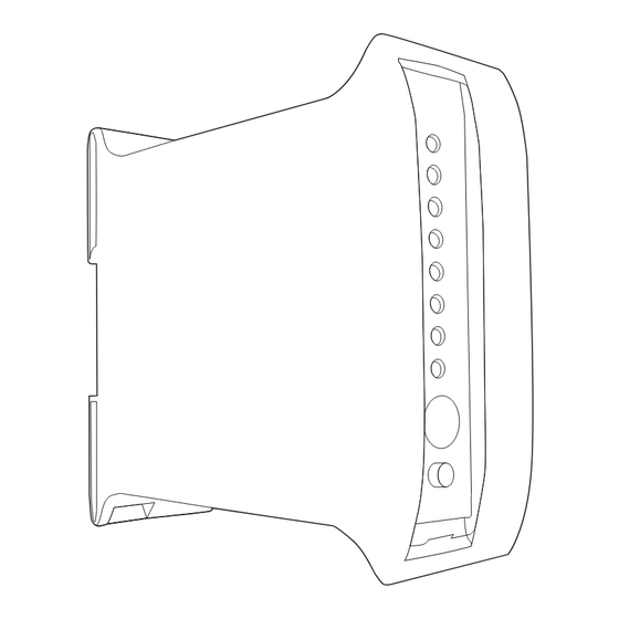
Page 9: Front Panel Indicators And Switches
FRONT PANEL INDICATORS AND SWITCHES The front panel has the following LEDs: LED Name Description NMRx Receiving an NMEA2000® message NMTx Transmitting an NMEA2000® message MoRx Receiving a Modbus message MoTx Transmitting a Modbus message MoFlt Invalid Modbus message CmFlt Communications error PGN became Data Not Available DefCm... -
Page 10: Fault Finding/Troubleshooting
FAULT FINDING/TROUBLESHOOTING The front panel indicators should be used to assist in fault finding as follows: 5.1 COMMUNICATIONS ERROR LEDs If the CmFlt led is lit this means that the unit detected an error in the communications param- eters being used on the Modbus interface. Please check that the transmission protocol EXACTLY matches the Modbus Communications Parameters in section 3.1 above. -
Page 11: Data Naming Convention
DATA NAMING CONVENTION Because it is easy to misunderstand base numbering system it is being shown in this document decimal / base 10 values are shown thus:- 10 = decimal value of ten Hexadecimal / base 16 values are shown thus:- 0x10 = decimal value of sixteen. - Page 12 MODBUS DATA REGISTERS The unit can receive NMEA2000 information from • 3 Engines • 8 Fuel Tanks • 8 Fresh Water Tanks • 8 Grey Water Tanks • 8 Black Water Tanks • 8 Oil Tanks • 3 Generators • 3 AC Sources •...
-
Page 13: Engine Instance 0 Registers
7.1 Engine Instance 0 Registers Engine Instance 0 – Single or PORT Engine Data Field Data Type, Range and Resolution Addr Addr 0x0000 0000 Engine Oil Pressure Unsigned 16 bit integer Range 0 – 6,553,200 Pa Resolution 1x10E+2 Pa 0x0001 0001 Engine Oil Temp Unsigned 16 bit integer... - Page 14 7.1 Engine Instance 0 Registers xxxx xxxx xxxx xx1x = Warning Level 2 xxxx xxxx xxxx x1xx = Power Reduction xxxx xxxx xxxx 1xxx = Maintenance Needed xxxx xxxx xxx1 xxxx = Engine Comm Error xxxx xxxx xx1x xxxx = Sub or Secondary Throttle xxxx xxxx x1xx xxxx = Neutral Start Protect xxxx xxxx 1xxx xxxx = Engine Shutting Down xxxx xxx1 xxxx xxxx = Reserved...
-
Page 15: Engine Instance 1 Registers
Engine Instance 1 Registers Engine Instance 1 – STARBOARD Engine Data Field Data Type, Range and Resolution Addr Addr 0x0011 0017 Engine Oil Pressure Unsigned 16 bit integer Range 0 – 6,553,200 Pa Resolution 1x10E+2 Pa 0x0012 0018 Engine Oil Temp Unsigned 16 bit integer Range 0 –... - Page 16 Engine Instance 1 – STARBOARD Engine Data Field Data Type, Range and Resolution Addr Addr 0x0011 0017 Engine Oil Pressure Unsigned 16 bit integer Range 0 – 6,553,200 Pa Resolution 1x10E+2 Pa 0x0012 0018 Engine Oil Temp Unsigned 16 bit integer Range 0 –...
- Page 17 xxxx xxxx xxxx x1xx = Power Reduction xxxx xxxx xxxx 1xxx = Maintenance Needed xxxx xxxx xxx1 xxxx = Engine Comm Error xxxx xxxx xx1x xxxx = Sub or Secondary Throttle xxxx xxxx x1xx xxxx = Neutral Start Protect xxxx xxxx 1xxx xxxx = Engine Shutting Down xxxx xxx1 xxxx xxxx = Reserved xxxx xx1x xxxx xxxx = Reserved xxxx x1xx xxxx xxxx = Reserved...
-
Page 18: Engine Instance 2 Registers
Engine Instance 2 Registers Engine Instance 2 – THIRD Engine Data Field Data Type, Range and Resolution Addr Addr 0x0022 0034 Engine Oil Pressure Unsigned 16 bit integer Range 0 – 6,553,200 Pa Resolution 1x10E+2 Pa 0x0023 0035 Engine Oil Temp Unsigned 16 bit integer Range 0 –... - Page 19 0x002C 0044 Engine Status 2 16 bit Status bitfield xxxx xxxx xxxx xxx1 = Warning Level 1 xxxx xxxx xxxx xx1x = Warning Level 2 xxxx xxxx xxxx x1xx = Power Reduction xxxx xxxx xxxx 1xxx = Maintenance Needed xxxx xxxx xxx1 xxxx = Engine Comm Error xxxx xxxx xx1x xxxx = Sub or Secondary Throttle xxxx xxxx x1xx xxxx = Neutral Start Protect xxxx xxxx 1xxx xxxx = Engine Shutting Down...
-
Page 20: Fuel Tank Registers
Fuel Tank Registers Fuel Tank Instance 0 Registers Data Field Data Type, Range and Resolution Addr Addr 0x0033 0051 Fluid Level Signed 16 bit integer Range -131.072% to +131.056% Resolution 0.004% 0x0034/ 0052/ Tank Capacity Unsigned 32 bit integer 0x0035 0053 0052 = MSW Range 0 –... - Page 21 Fuel Tank Instance 6 Registers Data Field Data Type, Range and Resolution Addr Addr 0x0045 0069 Fluid Level Signed 16 bit integer Range -131.072% to +131.056% Resolution 0.004% Unsigned 32 bit integer 0x0046/ 0070/ Tank Capacity 0x0047 0071 0070 = MSW Range 0 –...
-
Page 22: Fresh Water Tank Registers
Fresh Water Tank Registers Fresh Water Tank Instance 0 Registers Data Field Data Type, Range and Resolution Addr Addr 0x004B 0075 Fluid Level Signed 16 bit integer Range -131.072% to +131.056% Resolu tion 0.004% 0x004C/ 0076/ Tank Capacity Unsigned 32 bit integer 0x004D 0077 0076 = MSW... - Page 23 Fresh Water Tank Instance 6 Registers Data Field Data Type, Range and Resolution Addr Addr 0x005D 0093 Fluid Level Signed 16 bit integer Range -131.072% to +131.056% Resolution 0.004% 0x005E/ 0094/ Tank Capacity Unsigned 32 bit integer 0x005F 0095 0094 = MSW Range 0 –...
-
Page 24: Grey Waste Water Tank Registers
Grey Waste Water Tank Registers Grey Water Tank Instance 0 Registers Hex Addr Data Field Data Type, Range and Resolution Addr 0x0063 0099 Fluid Level Signed 16 bit integer Range -131.072% to +131.056% Resolution 0.004% Unsigned 32 bit integer 0x0064/ 0100/ Tank Capacity 0x0065... - Page 25 Grey Water Tank Instance 6 Registers Data Field Data Type, Range and Resolution Addr Addr 0x0075 0117 Fluid Level Signed 16 bit integer Range -131.072% to +131.056% Resolution 0.004% Unsigned 32 bit integer 0x0076/ 0118/ Tank Capacity 0x0077 0119 0118 = MSW Range 0 –...
-
Page 26: Oil Tank Registers
Oil Tank Registers Oil Tank Instance 0 Registers Hex Addr Data Field Data Type, Range and Resolution Addr 0x007B 0119 Fluid Level Signed 16 bit integer Range -131.072% to +131.056% Resolution 0.004% Unsigned 32 bit integer 0x007C/ 0120/ Tank Capacity 0x007D 0121 0120 = MSW... - Page 27 Oil Tank Instance 6 Registers Data Field Data Type, Range and Resolution Addr Addr 0x008D 0141 Fluid Level Signed 16 bit integer Range -131.072% to +131.056% Resolution 0.004% Unsigned 32 bit integer 0x008E/ 0142/ Tank Capacity 0x008F 0143 0142 = MSW Range 0 –...
-
Page 28: Black Water Tank Registers
Black Water Tank Registers Black Water Tank Instance 0 Registers Hex Addr Data Field Data Type, Range and Resolution Addr 0x0093 0147 Fluid Level Signed 16 bit integer Range -131.072% to +131.056% Resolution 0.004% Unsigned 32 bit integer 0x0094/ 0148/ Tank Capacity 0x0095 0149... - Page 29 Black Water Tank Instance 6 Registers Data Field Data Type, Range and Resolution Addr Addr 0x00A5 0165 Fluid Level Signed 16 bit integer Range -131.072% to +131.056% Resolution 0.004% Unsigned 32 bit integer 0x00A6/ 0166/ Tank Capacity 0x00A7 0167 0166 = MSW Range 0 –...
-
Page 30: Ac Instance 0 Registers
AC Instance 0 Registers AC Instance 0 - Single or PORT AC Instance Hex Addr Data Field Data Type, Range and Resolution Addr 0x00AB 0171 AC Type Unsigned 16 bit integer Range 0 – 2, 0 = Bus, 1 = Utility, 2 = Generator Resolution 1 0x00AC 0172... -
Page 31: Ac Instance 1 Registers
7.10 AC Instance 1 Registers AC Instance 1 - Second or STBD AC Instance Hex Addr Data Field Data Type, Range and Resolution Addr 0x00B0 0176 AC Type Unsigned 16 bit integer Range 0 – 2, 0 = Bus, 1 = Utility, 2 = Generator Resolution 1 0x00B1 0177... -
Page 32: Ac Instance 2 Registers
7.11 AC Instance 2 Registers AC Instance 2 – Third AC Instance Hex Addr Data Field Data Type, Range and Resolution Addr 0x00B5 0181 AC Type Unsigned 16 bit integer Range 0 – 2, 0 = Bus, 1 = Utility, 2 = Generator Resolution 1 0x00B6 0182... -
Page 33: Ac Instance 3 Registers
7.12 AC Instance 3 Registers AC Instance 3 – Fourth AC Instance Hex Addr Data Field Data Type, Range and Resolution Addr 0x00BA 0186 AC Type Unsigned 16 bit integer Range 0 – 2, 0 = Bus, 1 = Utility, 2 = Generator Resolution 1 0x00BB 0187... -
Page 34: Ac Instance 4 Registers
7.13 AC Instance 4 Registers AC Instance 4 – Fifth AC Instance Hex Addr Data Field Data Type, Range and Resolution Addr 0x00BF 0191 AC Type Unsigned 16 bit integer Range 0 – 2, 0 = Bus, 1 = Utility, 2 = Generator Resolution 1 0x00C0 0192... -
Page 35: Ac Instance 5 Registers
7.14 AC Instance 5 Registers AC Instance 5 – Sixth AC Instance Hex Addr Data Field Data Type, Range and Resolution Addr 0x00C4 0196 AC Type Unsigned 16 bit integer Range 0 – 2, 0 = Bus, 1 = Utility, 2 = Generator Resolution 1 0x00C5 0197... -
Page 36: Battery Bank Registers
7.15 Battery Bank Registers Battery Bank Instance 0 Registers Hex Addr Data Field Data Type, Range and Resolution Addr 0x015F 0351 Battery Voltage Signed 16 bit integer Range ± 327.64 Volts Resolution 1x10E-2 Volts 0x0160 0352 Battery Current Signed 16 bit integer Range ±... - Page 37 Battery Bank Instance 4 Registers Hex Addr Data Field Data Type, Range and Resolution Addr 0x016B 0363 Battery Voltage Signed 16 bit integer Range ± 327.64 Volts Resolution 1x10E-2 Volts 0x016C 0364 Battery Current Signed 16 bit integer Range ± 3,276.4 Amps Resolution 1x10E-1 Amps 0x016D 0365...
-
Page 38: Battery Charger Instance 0 Registers
7.16 Battery Charger Instance 0 Registers Battery Charger Instance 0 First Connected Battery Data Registers Hex Addr Data Field Data Type, Range and Resolution Addr 0x0177 0375 Operating State 16 bit field Charge Mode xxxx xxxx xxxx 0000 = Not Charging Charger Enab/Dis xxxx xxxx xxxx 0001 = Bulk Equalisation Pend... - Page 39 xxxx xxxx 0000 xxxx = Standalone Mode xxxx xxxx 0001 xxxx = Primary Mode xxxx xxxx 0010 xxxx = Secondary Mode xxxx xxxx 0011 xxxx = Echo Mode xxxx xxxx 1110 xxxx = Error xxxx xxxx 1111 xxxx = Data not available xxxx xx00 xxxx xxxx = Charger Off/Disabled xxxx xx01 xxxx xxxx = Charger On/Enabled xxxx xx10 xxxx xxxx = Error...
-
Page 40: Battery Charger Instance 1 Registers
7.17 Battery Charger Instance 1 Registers Battery Charger Instance 1 First Connected Battery Data Registers Hex Addr Data Field Data Type, Range and Resolution Addr 0x017D 0381 Operating State 16 bit field Charge Mode xxxx xxxx xxxx 0000 = Not Charging Charger Enab/Dis xxxx xxxx xxxx 0001 = Bulk Equalisation Pend... - Page 41 xxxx xxxx 0000 xxxx = Standalone Mode xxxx xxxx 0001 xxxx = Primary Mode xxxx xxxx 0010 xxxx = Secondary Mode xxxx xxxx 0011 xxxx = Echo Mode xxxx xxxx 1110 xxxx = Error xxxx xxxx 1111 xxxx = Data not available xxxx xx00 xxxx xxxx = Charger Off/Disabled xxxx xx01 xxxx xxxx = Charger On/Enabled xxxx xx10 xxxx xxxx = Error...
-
Page 42: Battery Charger Instance 2 Registers
7.18 Battery Charger Instance 2 Registers Battery Charger Instance 2 First Connected Battery Data Registers Hex Addr Data Field Data Type, Range and Resolution Addr 0x0183 0387 Operating State 16 bit field Charge Mode xxxx xxxx xxxx 0000 = Not Charging Charger Enab/Dis xxxx xxxx xxxx 0001 = Bulk Equalisation Pend... - Page 43 xxxx xxxx 0000 xxxx = Standalone Mode xxxx xxxx 0001 xxxx = Primary Mode xxxx xxxx 0010 xxxx = Secondary Mode xxxx xxxx 0011 xxxx = Echo Mode xxxx xxxx 1110 xxxx = Error xxxx xxxx 1111 xxxx = Data not available xxxx xx00 xxxx xxxx = Charger Off/Disabled xxxx xx01 xxxx xxxx = Charger On/Enabled xxxx xx10 xxxx xxxx = Error...
-
Page 44: Battery Charger Instance 3 Registers
7.19 Battery Charger Instance 3 Registers Battery Charger Instance 3 First Connected Battery Data Registers Hex Addr Data Field Data Type, Range and Resolution Addr 0x0189 0393 Operating State 16 bit field Charge Mode xxxx xxxx xxxx 0000 = Not Charging Charger Enab/Dis xxxx xxxx xxxx 0001 = Bulk Equalisation Pend... - Page 45 xxxx xxxx 0000 xxxx = Standalone Mode xxxx xxxx 0001 xxxx = Primary Mode xxxx xxxx 0010 xxxx = Secondary Mode xxxx xxxx 0011 xxxx = Echo Mode xxxx xxxx 1110 xxxx = Error xxxx xxxx 1111 xxxx = Data not available xxxx xx00 xxxx xxxx = Charger Off/Disabled xxxx xx01 xxxx xxxx = Charger On/Enabled xxxx xx10 xxxx xxxx = Error...
-
Page 46: Switch Bank Status And Control Registers
7.20 Switch Bank Status and Control Registers The 3155 unit supports up to 8 banks each of 28 switches as grouped by the NMEA2000 standard. Each switch is accessible as either 224 (8 x 28) individual switches or grouped together in 8 Holding Registers designated as Instance 0 to Instance 7. -
Page 47: Switch Bank Holding Registers
7.21 Switch Bank Holding Registers Switch Bank Instance 0 Holding Registers Hex Addr Data Field Data Type, Range and Resolution Addr 0x018F 0399 Switches 1 – 8 16 bit field SSxx xxxx xxxx xxxx = Switch 1 bits xxSS xxxx xxxx xxxx = Switch 2 bits xxxx SSxx xxxx xxxx = Switch 3 bits xxxx xxSS xxxx xxxx = Switch 4 bits xxxx xxxx SSxx xxxx = Switch 5 bits... - Page 48 Hex Addr Data Field Data Type, Range and Resolution Addr 0x0194 0404 Switches 9 –16 16 bit field SSxx xxxx xxxx xxxx = Switch 9 bits xxSS xxxx xxxx xxxx = Switch 10 bits xxxx SSxx xxxx xxxx = Switch 11 bits xxxx xxSS xxxx xxxx = Switch 12 bits xxxx xxxx SSxx xxxx = Switch 13 bits xxxx xxxx xxSS xxxx = Switch 14 bits...
- Page 49 Hex Addr Data Field Data Type, Range and Resolution Addr 0x0199 0409 Switches 17 –24 16 bit field SSxx xxxx xxxx xxxx = Switch 17 bits xxSS xxxx xxxx xxxx = Switch 18 bits xxxx SSxx xxxx xxxx = Switch 19 bits xxxx xxSS xxxx xxxx = Switch 20 bits xxxx xxxx SSxx xxxx = Switch 21 bits xxxx xxxx xxSS xxxx = Switch 22 bits...
- Page 50 Hex Addr Data Field Data Type, Range and Resolution Addr 0x019E 0414 Switches 25 –28 16 bit field xxxx xxxx SSxx xxxx = Switch 25 bits xxxx xxxx xxSS xxxx = Switch 26 bits xxxx xxxx xxxx SSxx = Switch 27 bits xxxx xxxx xxxx xxSS = Switch 28 bits Values as per bit value table above Switch Bank Instance 4 Holding Registers...
- Page 51 Switch Bank Instance 5 Holding Registers Hex Addr Data Field Data Type, Range and Resolution Addr 0x01A3 0419 Switches 1 – 8 16 bit field SSxx xxxx xxxx xxxx = Switch 1 bits xxSS xxxx xxxx xxxx = Switch 2 bits xxxx SSxx xxxx xxxx = Switch 3 bits xxxx xxSS xxxx xxxx = Switch 4 bits xxxx xxxx SSxx xxxx = Switch 5 bits...
- Page 52 Hex Addr Data Field Data Type, Range and Resolution Addr 0x01A8 0424 Switches 9 –16 16 bit field SSxx xxxx xxxx xxxx = Switch 9 bits xxSS xxxx xxxx xxxx = Switch 10 bits xxxx SSxx xxxx xxxx = Switch 11 bits xxxx xxSS xxxx xxxx = Switch 12 bits xxxx xxxx SSxx xxxx = Switch 13 bits xxxx xxxx xxSS xxxx = Switch 14 bits...
- Page 53 Hex Addr Data Field Data Type, Range and Resolution Addr 0x01AD 0429 Switches 17 –24 16 bit field SSxx xxxx xxxx xxxx = Switch 17 bits xxSS xxxx xxxx xxxx = Switch 18 bits xxxx SSxx xxxx xxxx = Switch 19 bits xxxx xxSS xxxx xxxx = Switch 20 bits xxxx xxxx SSxx xxxx = Switch 21 bits xxxx xxxx xxSS xxxx = Switch 22 bits...
-
Page 54: Maintenance
MAINTENANCE ● Clean the unit with a soft cloth. ● Do not use chemical cleaners as they may remove paint or markings or may corrode the enclosure or seals. ● Ensure that the unit is mounted securely and cannot be moved relative to the mounting surface. -
Page 55: Technical Specification
TECHNICAL SPECIFICATION As Oceanic Systems (UK) Ltd are constantly improving their products ass specifications are subject to change without notice. Oceanic System’s products are designed to be accurate and reliable however they should only be used as aids to navigation and not as a replacement for traditional navigation aids and techniques. - Page 56 Electrical and Mechanical Parameter Value Comment Operating Voltage 9 to 32 Volts DC Voltage Power Consumption 50mA Average Operating Load Equivalence Number Reverse Battery Protection Indefinately Load Dump Protection SAE J1113 Size 120x100x35mm Weight 160gm Environmental Parameter Value IEC 60954 Classification Protected Degree of Protection IP40...
-
Page 57: Technical Support
Email: sales@osukl.com Web: www.osukl.com Copyright © 2017 Oceanic Systems (UK) Ltd. All rights reserved.Our policy is one of continuous product improvement so product specifications are subject to change without notice. Oceanic Systems products are designed to be accurate and reliable. However, they should be used only as aids to vessel monitoring, and not as a replacement for traditional navigation and vessel monitoring techniques. -
Page 58: Warranty
Systems sole obligation hereunder, provided product is returned pursuant to the return requirements below, shall be limited to the repair or replacement, at Oceanic Systems option, of any product not meeting the above limited warranty and which is returned to Oceanic Systems; or if Oceanic Systems is unable to deliver a replacement that is free from defects in materials or workmanship, Purchaser’s... -
Page 59: Oceanic System Product Map
58 of 59... - Page 60 59 of 59...
Need help?
Do you have a question about the NMEA2000 3155 and is the answer not in the manual?
Questions and answers