Advertisement
Advertisement
Table of Contents

Related Manuals for REXON DP3800RF


Summary of Contents for REXON DP3800RF
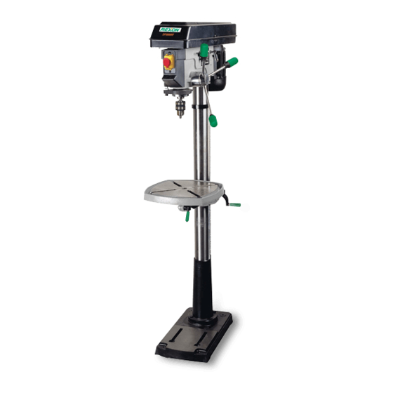
- Page 1 ® 15 IN. (381 MM) DRILL PRESS DP3800RF INSTRUCTION MANUAL...
- Page 2 CONTENTS P 1 - 11 The original instruction manual is in English.
- Page 3 CARTON CONTENTS UNPACKING Carefully unpack the drill press and all its parts, and compare against the list and the illustration below. Place the drill press on a secure surface and examine it carefully. WARNING! • To avoid injury from unexpected starting or electrical shock, do not plug the power cord into a source of power during unpacking and assembly.
- Page 4 General Safety Rules 9. USE PROTECTIVE EQUIPMENT. Use safety glasses. Use face or dust mask if WARNING ! When using electric tools cutting operations create dust. basic safety precautions should always 10. CONNECT DUST EXTRACTION be followed to reduce the risk of fire, EQUIPMENT.
- Page 5 20. CHECK DAMAGED PARTS. Before Do not operate this tool until it is assembled further use of the tool, it should be and installed according to the instructions. carefully checked to determine that it 1. Your drill press must be bolted securely will operate properly and perform its To a workbench.
-
Page 6: Environmental Protection
15.Never turn your drill press on before Keep hands away from blade: clearing the table of all objects (tools, Failure to keep your hands scraps of wood, etc.).16.Before starting away from the blade will result in serious personal injury. the operation, jog the motor switch to make sure the drill bit does not wobble or vibrate. -
Page 7: Specifications
Specifications ASSEMBLING COLUMN TO BASE (FIG. 2) ITEM 1. Position the base (2) on a flat work surface. 625W, 220V~, Motor (rated input) 2. Place the column (1) on the base, 60Hz aligning the mounting holes to the base. Speed (min 12 (250-3100) 3. -
Page 8: Adjustments Instructions
the column as far as possible. Align the 5. Using a rubber mallet, or a hammer and head with the base. a block of wood, firmly tap the chuck 2. Using the 5 mm hex wrench, tighten the upward into position on the spindle two head lock set screws (3) on the right shaft. - Page 9 Hold it in place while loosening and WARNING! To prevent personal injury, removing only the lock nut (6). always disconnect the plug from the power 4. With the screwdriver still engaged in the source when making any adjustments. notch, loosen the inner nut (10) just until 1.
- Page 10 LASER ADJUSTMENT (FIG. 16, 17, 18) Cross Hair Alignment (FIG. 16, 18) NOTE: The laser assembly has been 7. Place board (12) flat on the table. Do not allow the board to move from this installed and preset at the factory. It should, however, be checked and any adjustments position;...
-
Page 11: Basic Drill Press Operation
Operating the Tool ON / OFF SWITCH PANEL (FIG. 20) The “ON / OFF” switch has a removable, safety key. With the key removed from the BASIC DRILL PRESS OPERATION switch, unauthorized and hazardous use by WARNING: To avoid possible injury, keep children and others is minimized. -
Page 12: Depth Scale
3. Make sure that the drill is centered in the Depth scale method chuck. NOTE: With the chuck quill assembly fully retracted the tip of the drill bit, the drill bit 4. Turn the chuck key clockwise to tighten the jaws. must be just slightly above the top of the workpiece. -
Page 13: General Maintenance
4. Tap the key wedge (4) lightly with a TILTING THE TABLE (FIG. 27) plastic tipped hammer, until the chuck NOTE: The table arm and support (1) and arbor fall out of the spindle. has a threaded hole with a locking set NOTE: Place one hand below the chuck to screw inserted for locking the table into a catch it when it falls out. - Page 14 LUBRICATION Ball bearings in the drill press are packed with grease at the factory and require no further lubrication. Use only mild soap and a damp cloth to clean the tool. Never let any liquid get inside the tool; never immerse any part of the tool into a liquid.
- Page 15 Fig. 3 Fig. 4 Fig. 1 Fig. 2 Fig. 5...
-
Page 16: On/Off Switch
Fig. 6 Fig. 9 Fig. 7 Fig. 10 ON/OFF SWITCH Fig. 8 Fig. 11... - Page 17 Fig. 15 Fig. 12 Vert adj Cross hair adj Fig. 16 Fig. 13 Fig. 14 Fig. 17...
- Page 18 Fig. 21 Fig. 18 Fig. 19 Fig. 22 Fig. 20 Fig. 23...
- Page 19 Fig. 27 Fig. 24 Fig. 25 Fig. 26...
- Page 20 DP3800RF PARTS LIST ORDER ONLY BY MODEL NUMBER AND PART NUMBER ID NO. Description Size Q’ty ID NO. Description Size Q’ty 0607 SWITCH BOX 0KPX HEX. NUT 1/2*20UNF T=6.5 2457 FLAT WASHER 0KQX M6*1.0 T=6 04Q4 STICKER 0KSM STRAIN RELIEF 056T COLUNM ASS’Y...
- Page 21 Schematic MODEL: DP3800RF 2JPC 36JG 36JH...
- Page 22 NOTES...
- Page 24 ®...
Need help?
Do you have a question about the DP3800RF and is the answer not in the manual?
Questions and answers