
Summary of Contents for Electrodata ATS-5X
- Page 1 ATS-5X User Manual Networked Communication Solutions, LLC Electrodata, Inc. Copyright 2015 Rev. 04/15...
-
Page 2: Table Of Contents
ATS-5X User Manual Page 2 of 44 Contents Introduction ..................................3 Overview ................................. 3 Interface .................................. 4 Assistance ................................4 Operation ..................................4 Instrument Power Up .............................. 4 Battery Operation ..............................4 USB Devices ................................4 2.3.1 Keyboard ................................. 4 2.3.2... -
Page 3: Introduction
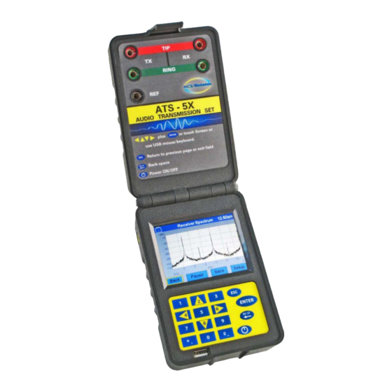
Page 3 of 44 Introduction Overview The ATS-5X is a hand-held test instrument for installation and troubleshooting of equipment or circuits in leased and dial-up networks. Figure 1 below shows an image of the product in operation. The following measurements and functions are provided: ... -
Page 4: Interface
The ATS-5X has a USB host port and can support a single USB drive, keyboard and/or mouse. A keyboard or mouse can be used to control the ATS-5X user interface, and a USB drive allows the user to save test results and update the ATS-5X software. -
Page 5: Mouse
FAT32, FAT16 or FAT12 file system in order to be considered a valid drive. If a software update file is on the drive, a message will be displayed asking if the ATS-5X software should be updated with the file. -
Page 6: User Interface
The various touchscreen displays have a number of common control elements that are used to setup the ATS-5X for measurements. Interaction with the controls using the touchscreen or USB mouse is straightforward; however, most actions using the keypad and USB keyboard require a control to be selected first. -
Page 7: Screen Elements
ATS-5X User Manual Page 7 of 44 Focused Control Active Control Figure 6 – Focused and Active Controls Focus is shifted from one control to the next by using the directional arrow keys on the keypad or USB keyboard. Once a... - Page 8 ATS-5X User Manual Page 8 of 44 “Pressing” the toggle control selects a new list item Figure 7 – Toggle Control Item Cycling 2.4.3.3 Selection List Control The selection list control displays a vertical list of text items and allows selection of one or more items, depending on the context.
- Page 9 ATS-5X User Manual Page 9 of 44 To expand the list in order to make a selection, press the control in the same manner as a button control (see Figure 9). Once the selection list is visible, the current selection row should be marked with a unique color in the same manner as the selection list control.
- Page 10 ATS-5X User Manual Page 10 of 44 Grid control circled Figure 11 – Grid Control 2.4.3.6 Text Entry Control The text entry control provides a means of specifying text as numbers and letters (see Figure 12). The control must first be activated to enter or change the text.
- Page 11 ATS-5X User Manual Page 11 of 44 Bksp: Backspace – delete the character to the left of the cursor in the text entry field at the top of the screen (Left arrow): Move the text entry field cursor one character to the left ...
-
Page 12: Screen Navigation
There are controls on each screen that allow the user to change to other screens. For instance, most screens have a Back button that returns the display to the previous screen. When the ATS-5X is first powered on, the Start-Up screen is displayed momentarily and then the Main Menu screen is displayed. -
Page 13: Screens
Start-up Screen After the ATS-5X is powered on, a splash screen is displayed while loading. This screen shows the results of the power- on self test in the upper left-hand corner, the product serial number in the lower left-hand corner and the software version in the lower right-hand corner. -
Page 14: Date & Time
Displays the Date & Time screen to allow adjustment of the date and time. 2.5.4 Date & Time The time and date that is maintained by the ATS-5X may be adjusted from the Date & Time screen, accessible from the Preferences screen. Figure 19 below shows the date and time adjustment. Seconds... -
Page 15: Setup
The Setup screen allows configuration of the ATS-5X line interface. Although Figure 22 shows one example of a configuration, the content and available selections on the screen are dependent upon the measurement mode previously selected. The ATS-5X line interface is influenced by the setup options as shown in Figure 20 and Figure 21. SETTINGS... - Page 16 ATS-5X User Manual Page 16 of 44 SETTINGS SETTINGS Interface: 2-Wire Interface: 2-Wire Bridging: On of Off Bridging: Transmitter: Transmitter: Transmitter Transmitter Source Z / 2 Source Z / 2 Source Z / 2 RING Source Z / 2 RING...
- Page 17 ATS-5X User Manual Page 17 of 44 Off-hook selection o No: A telephone on-hook condition is presented to the transmit jack tip and ring. o Yes: A telephone off-hook condition is presented to the transmit jack tip and ring.
-
Page 18: Self-Test
Self-Test The ATS-5X has a self-test functionality to allow the user to verify proper operation. The Self-Test screen can be accessed by pressing the Self-Test button on the System Menu screen. This will begin a sequence of tests that require user interaction. -
Page 19: Equipment Connection
The first measurement configuration has the circuit under test connected to the tip and ring of the ATS-5X transmitter jack as shown in Error! Reference source not found.. The second measurement configuration requires the circuit under test to be connected to the ATS-5X transmitter jack in reverse fashion, as shown in Figure 25. -
Page 20: Delay Emulation
This functionality may be used to simulate mid-span delay or echo from a far-end device. The ATS-5X must be connected in a 4-wire manner in either configuration. The repeater configuration is as shown in Figure 26 and the far-end configuration is as shown in Figure 27. -
Page 21: Measurements And Functions
ATS-5X User Manual Page 21 of 44 End Device ATS-5X Receiver Termination Z RING Source Z / 2 Transmitter Source Z / 2 RING Figure 27 – Delay Emulator Far-End Echo Generator Setup Measurements and Functions 2.7.1 Level / Frequency / Noise 2.7.1.1... - Page 22 2.7.1.5 Saving Results To save the measurements, insert a valid memory device into the ATS-5X USB port. Once the memory device is recognized, the screen will display two additional controls for saving results— Time Record and Freq Record—as shown in Figure 30.
- Page 23 (see Figure 31). Once started, the results capture will continue until the Stop button is pressed. The Stop button must be pressed before the memory device is removed from the ATS-5X USB port to ensure that the results are properly saved.
-
Page 24: Impulse Noise
ATS-5X User Manual Page 24 of 44 Figure 32 – Level/Freq/Noise Frequency Recording 2.7.2 Impulse Noise 2.7.2.1 Overview The impulse noise measurement counts the number of times that receive signal level momentarily exceeds a selectable threshold. The measurement is run for a predetermined amount of time and may be run in the presence of a holding tone. -
Page 25: Longitudinal Balance
Save: Saves the current test results to a text file on the USB drive inserted into the ATS-5X. If there is not a valid drive, a message is displayed to indicate this. Setup: Show the Setup screen. - Page 26 Aborts the current longitudinal balance measurement (see Figure 35). Any partial results are discarded. Save: Save the tone sweep longitudinal balance results to a USB drive in the ATS-5X USB port (see Figure 36). A message will be displayed to indicate if there is no valid USB drive attached.
-
Page 27: Dialer
The Dialer screen (see Figure 37) allows DTMF or pulse dialing and capture of received DTMF digits. A string of up to 30 digits may be dialed using fixed on and off times for DTMF dialing, or fixed on-hook and off-hook times for pulse dialing. The ATS-5X microphone may also be used in the Dialer screen to allow voice calls. - Page 28 ATS-5X User Manual Page 28 of 44 The DTMF digit capturing feature will display the last 16 valid digits received. Any of these digits mat be selected to display the level, frequency and time statistics for that digit. The measurements for all 16 digits may be saved to a USB drive.
- Page 29 Dial button has been pressed. To enter the letters A, B, C or D into the Dial Sequence text entry, use a USB keyboard attached to the ATS-5X USB port, or enter the letters with the On-Screen Keyboard screen.
-
Page 30: Delay Emulator (4-Wire)
Setup The Delay Emulator function configures the line interface of the ATS-5X to be 4-wire fixed as a delayed repeater of the receiver with no filtering. As such, the Setup screen does not show adjustments for these setup parameters (see Figure... -
Page 31: Echo Measurement
The echo measurement (Figure 42) provides a method of characterizing the time delay and return amplitude of echoes in a circuit. The ATS-5X does this by transmitting a stimulus and measuring the response when the Measure button is pressed—the measurement is not made continuously. For this reason, the echo measurement must be conducted on a quiet circuit. - Page 32 Once a measurement has been initiated, it can be stopped by pressing the Abort button. Save: Store the echo measurement results to the USB flash inserted in the ATS-5X USB port. This button is only visible if an echo measurement has been performed and a valid USB drive is inserted into the ATS-5X USB port.
-
Page 33: Spectrum
Overview The 23-tone measurement (see Figure 45) provides a quick overview of the frequency response and distortion of a circuit in the voice band. The ATS-5X may act as a transmitter or receiver in an end-to-end measurement setup, or as... -
Page 34: P/Ar Measurement
P/AR Measurement 2.7.9.1 Overview The peak-to-average ratio measurement (see Figure 46) is one method of quantifying the distortion of a circuit. The ATS-5X is capable of simultaneous transmission and measurement of the P/AR signal so that the measurement may be... -
Page 35: Slope Measurement
404 Hz and 2804 Hz with the received signal level at 1004 Hz and displays the relative difference. When the ATS-5X transmitter is set to Slope and the Slope Measurement screen is active, the transmitter will transmit a single tone that periodically changes frequency between 404, 1004 and 2804 Hz. -
Page 36: Maintenance
Return to the previous screen Save: Store the Slope measurement results in text format to the USB flash inserted in the ATS-5X USB port. If no valid drive is attached, a message is displayed to indicate this. Setup: Show the Setup screen. -
Page 37: Calibration
Once downloaded, the software file should be placed on the root directory of a valid USB drive (see section 2.3.4). The name of the software file must be ATS5XSFT.DAT to be recognized by the ATS-5X. The name of the file must be all upper-case or lower-case letters, and there cannot be another file on the root directory of the USB drive with the same name but different letter case. -
Page 38: Specifications
ATS-5X User Manual Page 38 of 44 Specifications The specifications are subject to change without notice. Transmitter Frequency Range: 50 Hz to 20 kHz Resolution: 1 Hz Accuracy: ±20 ppm Transmit Level Range: -40 dBm to +10 dBm Resolution: 0.01 dB Harmonic Distortion (to 20 kHz) <... - Page 39 ATS-5X User Manual Page 39 of 44 Filters C-Message 3.4 kHz Flat D Filter 15 kHz Flat 1010 Hz Notch C-Message & 1010 Hz Notch None (20 kHz Flat) 23-Tone Transmit Level Range: -40 dBm to +4 dBm Resolution: 0.01 dB Accuracy: ±0.2 dB...
- Page 40 ATS-5X User Manual Page 40 of 44 Holding Tone Tone Filter: Standard 1010 Hz Notch Range: 950 to 1050 Hz Dialer DTMF Detection – Level Range: -20 dBm to +10 dBm Resolution: 0.01 dB Accuracy: ±0.2 dB DTMF Detection – Frequency...
- Page 41 ATS-5X User Manual Page 41 of 44 Attenuation Range: 0 to 30 dB Resolution: 0.01 dB Accuracy: ±0.3 dB Peak to Average Ratio Transmitter Level Range: -40 dBm to +2 dBm Resolution: 0.01 dB Accuracy: ±0.2 dB Transmitter Waveform P/AR ratio: 100 ±...
- Page 42 ATS-5X User Manual Page 42 of 44 Power Adapter AC input: 100 – 240V RMS, 50 – 60 Hz, 0.8A DC output: 12 V positive center, 2500 mA Battery Life: 6 hours average on full charge for new battery Data Storage...
-
Page 43: Abbreviations
Ratios of quantities other than power are typically expressed in the following manner: Decibel with reference to 1 A measure of power. When a device like the ATS-5X measures voltage Milliwatt of power only, reference impedance is assumed, such as 600Ω. Power expressed... - Page 44 Where T is usually the length of one period of a periodic waveform. Receive Transmit µs,µsec Microsecond Measure of time. 1 Microsecond = 10 Second Universal Serial Bus A communication standard. The ATS-5X uses a USB port to allow communication with devices such as USB keyboards.
Need help?
Do you have a question about the ATS-5X and is the answer not in the manual?
Questions and answers