Advertisement
Quick Links
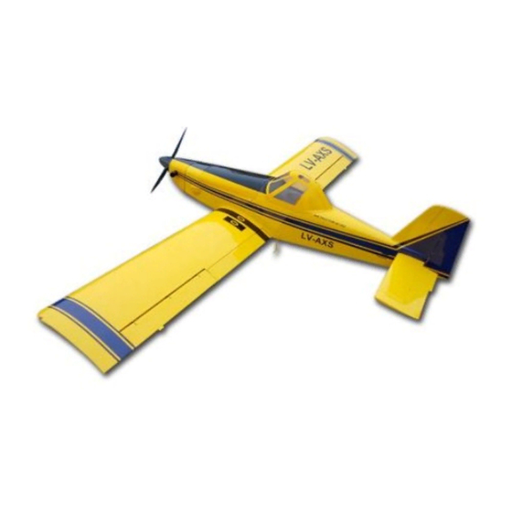
110" Air Tractor 502 30-60CC
WING SPAN: 110" (2800mm)
LENGTH: 78.5" (2000mm)
WING AREA: 1704sq in
FLYING WEIGHT: 19-20.9lbs (7100g-7800g)
ENGINE:30-60cc gas
RADIO: 4CH / 6 servos
Features:
Carbon Fiber - Wing Tube, Stab Tube, Main Gear, and Tail gear
Fiberglass Servo Arms and Control Horns
Canister ready Fuse
Adjustable Push rods
Ringed Cowl
Pre-Drilled Hinges
Removable Rudder, 2 Piece Removable Wings and 2 Piece Removable Stabs.
Carbon rods incorporated in fuse and wings to keep airframe stiff
Advertisement

Summary of Contents for AeroPlus Air Tractor 502
- Page 1 110" Air Tractor 502 30-60CC WING SPAN: 110" (2800mm) LENGTH: 78.5" (2000mm) WING AREA: 1704sq in FLYING WEIGHT: 19-20.9lbs (7100g-7800g) ENGINE:30-60cc gas RADIO: 4CH / 6 servos Features: Carbon Fiber - Wing Tube, Stab Tube, Main Gear, and Tail gear ...
- Page 2 Congratulations on your purchase of your new AeroPlus RC 110” Airtractor 502. We hope that you will enjoy this plane and that it will exceed your expectations in what a model airplane can be. Thank you, AeroPlus RC Unpacking Carefully unpack the model, when opening the plastic bags make sure you do not to cut any covering on the model.
- Page 3 Landing gear: First, screw the flange nut into the axle, then use the self-locking nut to lock the axle on the landing gear, remember to use a washer between the self-locking nut and the landing gear, and then press a plastic gasket, The sequence of the shims is to load the wheel into the axle, and finally insert the pin into the axle hole to lock the wheel.
-
Page 4: Tail Wheel Installation
Tail wheel installation: First attach the rear wheel frame plate with three 3mm screws and washers. Using the hollow screws and nuts on the tail wheel frame plate. Insert the tail wheel shaft through the hollow screw (see photos) rear wheel steering seat screws Will be wheel axle locking, tail wheel steering seat screw to be aligned for the axle to be polished surface. - Page 6 Flaps: The epoxy rudder angle is glued to the wing; the carbon fiber rudder angle is glued to the flap, with two holes in the middle. The two rudders are then connected using a screw.
-
Page 7: Rudder Installation
Rudder Installation: The tail wheel must be installed. First, drill the four screw holes with a hand drill and drip CA in the holes to harden them. Then lock the servo with self-tapping screw. The mounting holes of the servo mounting plate also need to be fast-dripped and then tightened with self-tapping screws. - Page 9 Cockpit cover installation: find the cockpit suitable placement, use paper tape to be fixed, and then use the drill on the left and right sides of the two holes to play, before and after the middle position of the play a hole. Pour a little bit of each hole into the quick-drying glue, and then use the self-tapping screw locking fixed.
-
Page 11: Cowl Installation
Cowl installation: Stick a piece of paper tape in the fixed mounting ears, longer than the ear to the fuselage of the double cut as far as possible with the ear parallel. And then put the paper tape buckle, and then paste it back to the paper, be careful not to have folds, paste a good tape after the machine from the machine, the paper tape to the tape, Body tear, in the hood against the punched paper tape holes can be used to drill a hole in a hand drill. - Page 13 Before you fly! We recommend the use of exponential. Suggested Set up: Wing flap: Flap are designed for 50 degrees of throw Aileron: 15-20 degrees 15-20% Expo Elevator: 15-20 degrees 15-20% Expo Rudder: 25-30 degrees 15-20% Expo Aileron: 35-45 degrees 30-60% Expo Elevator: 40 degrees 30-60% Expo Rudder: 60 degrees 30-60% Expo For your maiden flights always use low rates, Also please remember that + and –...
Need help?
Do you have a question about the Air Tractor 502 and is the answer not in the manual?
Questions and answers