Advertisement
Quick Links
Advertisement

Subscribe to Our Youtube Channel
Summary of Contents for Northern Computers EntryProx
- Page 1 EntryProx ™ Quick Reference Installation Guide TD1131 rev0800...
-
Page 2: Table Of Contents
Installing EntryProx ......1-1 Wiring EntryProx ......2-1... - Page 3 Installation Introduction EntyProx ™...
-
Page 4: Introduction
™ INTRODUCTION This User’s Guide is intended for experienced installers of the EntryProx unit. It is not intended for routine use and does not replace the more comprehensive information contained in the EntryProx Installation/Programming Manual. The Guide provides basic informa- tion and instructions for installing, wiring, and programming the EntryProx unit. -
Page 5: Product Overview
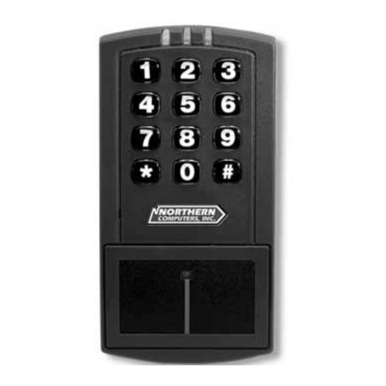
26-bit card. All programming options are performed using the controller keypad. Unit Capacity The EntryProx unit can accommodate up to 2,000 users. Each user can have a card/tag, a PIN code, or a card/tag PLUS a PIN code. Transactions A maximum of 1,000 transactions can be stored in the EntryProx unit. - Page 6 Installation Introduction EntyProx ™ Figure 1: EntryProx Assembly Parts 1: F ABLE AC ORY UPPLIED AR S ESCRIP ION . Controller Keypad Unit G. Press to Exit label B. Controller Keypad Backplate H. Silicone Rubber "Dogbone" C. Cable ssemblies I. Self- dhering Pads D.
- Page 7 EntyProx ™ Installation Introduction 3: S ABLE PECIFICA IONS A EGORY EQUIREMEN S ENVIRONMEN AL -20° F to 130° F perating Temperature (-28° C to 54° C) 5% to 95% relative humidity, non- perating Humidity condensing ELEC RICAL Power Supply/Current Requirements (Does not include locking device or 10 –...
-
Page 8: Installing Entryprox
• Mounting the EntryProx unit outside a secured area, such as outside a main entrance. • Wiring the EntryProx unit for door locks and alarm out-puts. In a secure installation the antenna housing is removed from the controller keypad and mounted outside a secured area. The blank filler piece is then inserted into the controller keypad in its place. - Page 9 Installation Section 1 EntyProx ™ Mounting the EntryProx Unit To mount the EntryProx unit to a wall surface, refer to Figure 2 and follow these instructions. Instructions: 1. Remove the hex screw located at the bottom of the EntryProx unit.
- Page 10 ™ Installation Section 1 Wiring the Controller Keypad for a Standard Installation To wire the EntryProx unit for a standard installation, refer to Figures 3 and 4 and follow these instructions. Instructions: 1. Touch a grounded object BEFORE touching the main circuit board to guard against possible static discharges.
- Page 11 5. Pull the wires through the backplate as shown in Figure 4. 6. Reattach the main circuit board to the controller keypad unit. 7. Attach the controller keypad unit to the mounted backplate and secure the EntryProx unit with a hex screw or tamper screw. 4: P...
- Page 12 In a secure installation, the antenna housing is removed from the controller keypad and is located no more than 10 feet away from the EntryProx unit. To wire the EntryProx unit for a secure installa- tion, refer to Figures 5 and 6 and follow these instructions.
- Page 13 11. Reattach the main circuit board to the controller keypad unit. 12. Attach the controller keypad unit to the mounted backplate and secure the EntryProx unit with a hex screw or tamper screw. 13. Run the additional antenna cable to the antenna housing location.
- Page 14 EntyProx ™ Installation Section 1 7: M IGURE OUNTING THE NTENNA ACKPLATE Moisture Release Holes Mounting and Wiring the Antenna Housing for a Secure Installation To mount and wire the antenna housing, refer to Figures 7 and 8 and follow these instructions. Instructions: 1.
- Page 15 Installation Section 1 EntyProx ™ 9: U IGURE SING THE ILLER IECE AS A EQUEST TO WITCH Selecting a Filler or Request to Exit Operation The filler piece replaces the antenna housing on the controller key- pad when you use the secure installation. If you are not going to use the filler piece as a Request to Exit switch: •...
-
Page 16: Wiring Entryprox
Wiring the EntryProx - Section 2 EntyProx ™ Section 2 - Wiring the EntryProx This section includes three wiring diagrams: • Wiring the main relay • Wiring the auxiliary relay • Wiring the Request to Exit switch Figure 10 illustrates the location of the four pin connectors on the main circuit board. - Page 17 Wiring the EntryProx - Section 2 EntyProx ™ 5: PIN C ABLE ONNEC OR ESCRIP IONS ONNEC OR OLOR Gray Main Relay, Normally Closed Green Main Relay, Normally Closed 1 (5-pin) Blue Main Relay, Common Black Ground ower In, +12 VDC...
- Page 18 WIRING THE MAIN RELAY The main relay for the door locking device is wired to connector P1 on the EntryProx main circuit board. To wire the EntryProx unit to the door locking device, refer to Figures 11 and 12 and follow these instructions.
- Page 19 6. Reattach the main circuit board to the controller keypad. 7. Reattach the controller keypad to the backplate and secure the EntryProx unit with a hex screw or tamper screw. Note: You can make the wiring connections for a gate actuator (diagram not shown) by connecting the Blue (C) wire and the Green (N/O) wire directly to the input.
- Page 20 The alarm shunt operation allows you to use the auxiliary relay to bypass a door contact that is monitored by a separate alarm system. If the entry or exit is controlled by the EntryProx unit, an intrusion alarm will not be generated if the door is opened using an access card or PIN number.
- Page 21 To wire the auxiliary relay, refer to Figures 13 and 14 and follow these instructions. Instructions: 1. Power off the EntryProx unit and remove the controller key pad from the backplate (if not already removed). 2. Remove the main circuit board from the controller keypad as shown in Figure 3.
- Page 22 EntyProx ™ Wiring the EntryProx - Section 2 14: W IGURE IRING ELAY FOR ROPPED ORCED LARM BLUE (C) ORANGE Door Contact (Monitored by EntryProx unit)
- Page 23 The Transaction Log records all Request to Exit usages for monitoring purposes. To wire the EntryProx unit for the Request to Exit switch, refer to Figures 15 and 16 and follow these instructions.
- Page 24 EntyProx ™ Wiring the EntryProx - Section 2 15: W IGURE IRING EQUEST TO WITCH WITH ONTACT 16: W IGURE IRING EQUEST TO WITCH ONTACT...
- Page 25 Wiring the EntryProx - Section 2 EntyProx ™ 2-10...
- Page 26 • The EntryProx unit does not control door lock or unlocking operations. • The EntryProx unit is not able to store codes in memory. • The main and auxiliary relay functions are turned off. For more information on programming the EntryProx unit for Wiegand operations, please contact your local distributor.
- Page 27 Programming the EntryProx - Section 3 EntyProx ™ 6: P ABLE ROGRAM OMMANDS If You Want o… Press Details nter program mode 99 # (Master Code) * Yellow L D blinks slowly Change master code 1 # (new code) * (repeat...
- Page 28 EntyProx ™ Programming the EntryProx - Section 3 6: P (continued) IGURE ROGRAMMING OMMANDS et propped door time ttt = propped door time, to (this sets time for both nearest 10's seconds, 44 # ttt # 0 # ** the Aux Relay and local entered as 10 –...
- Page 29 Programming the EntryProx - Section 3 EntyProx ™ 6: P (continued) IGURE ROGRAMMING OMMANDS ode – Transaction Event 1 – Access Denied 2 – Program Denied 3 – Program Mode 4 – Request to Exit 5 – Door Ajar 6 – Door Closed 7 –...
- Page 30 EntyProx ™ Programming the EntryProx - Section 3 7: LED I ABLE NDICA ORS AND UDIO PERA IONS LED or Visual/Audible Description Sounder Condition Yellow LED low blink Unites is in Program mode Verify mode is active (checking Rapid blink...
-
Page 31: Programming Hints
Programming the EntryProx - Section 3 EntyProx ™ PROGRAMMING HINTS Wiegand Programming: • If you are using 26-bit cards with one common facility code, enter that code under Programming Code 32, parameter 2, facility code, to allow batch programming or facility code only operation. - Page 33 5007 South Howell Avenue • Milwaukee, WI 53207 • (800)323-4576 www.nciaccess.com...
Need help?
Do you have a question about the EntryProx and is the answer not in the manual?
Questions and answers