Table of Contents
Advertisement
Quick Links
Advertisement
Table of Contents

Related Manuals for ERL TESLA 4000


Summary of Contents for ERL TESLA 4000
- Page 1 TESLA 4000 Power System Recorder User Manual Version 3.0 Rev 1...
-
Page 3: Preface
Microsoft Corporation. ® HyperTerminal is a registered trademark of Hilgraeve. ® Modbus is a registered trademark of Modicon. ® Contact Information ERLPhase Power Technologies Ltd Website: www.erlphase.com Email: info@erlphase.com Technical Support Email: support@erlphase.com Tel: 1-204-477-0591 D02771R03.01 TESLA 4000 User Manual... -
Page 5: Using This Guide
Click the right mouse button. Recordings Menu items and tabs are shown in italics. service User input or keystrokes are shown in bold. Text boxes similar to this one Relate important notes and information. Indicates more screens. D02771R03.01 TESLA 4000 User Manual... -
Page 7: Table Of Contents
Version Compatibility ............... ix PC System Requirements and Software Installation ....xi 1 Overview ..............1-1 TESLA System Description..........1-1 TESLA 4000 Features ............. 1-2 Front Panel ..............1-6 Rear Connections ............1-6 2 Installation and Safety Instructions ..... 2-1 Introduction .............. -
Page 8: Table Of Contents
Meter Groups ..............9-55 Trend Logging..............9-56 Printing................9-58 10 Record and Log Management......10-1 Records................10-1 Trend Log............... 10-4 Event Log............... 10-6 Audit Trail............... 10-8 11 Continuous Disturbance Recording....11-1 12 Graphing Records..........12-1 TESLA 4000 User Manual D02771R03.01... - Page 9 Health monitoring and self-recovery features ....15-1 Maintenance Functions and Diagnostic Tools ....15-3 16 PMU Functionality..........16-1 Overview ................ 16-1 TESLA 4000 PMU Features .......... 16-2 Communication with the PMU........16-7 Setting up PMU Communication Mode......16-7 PMU Configuration............16-10 PMU Metering ..............
- Page 10 Split Core CT ..............G-15 DC Input Module ............G-16 Appendix H Recommended Spare Parts List....H-1 Appendix I TESLA Handling and Disposition ....I-1 Appendix J TESLA 4000 Drawings ......J-1 Appendix K IEC 61850 Implementation ....... K-1 Protocol Implementation Conformance Statement (PICS) ............K-1 Model Implementation Conformance Statement (MICS) ............
-
Page 11: Version Compatibility
Version Descriptions Version Compatibility For version compatibility check D02785-TESLA 4000 Firmware User Release Description which is available on the ERLPhase website: www.erlphase.com. This manual was created using the following software and firmware versions: TESLA 4000 Firmware v2.0 TESLA Control Panel v3.0 RecordGraph v5.2... -
Page 13: Pc System Requirements And Software Installation
The installation program launches automatically. Installation may take a few minutes to start. 1. Not all Windows 10 versions are compatible with modem and serial com- munications to ERLPhase IEDs. Refer to TESLA Control Panel release notes for details. D02771R03.01 TESLA 4000 User Manual... - Page 14 “TESLA Control Panel Installation” on page 3-1. Once these steps are complete, go to the First Time Start-Up section for details on launching TESLA Control Panel (see “First Time Start-Up” on page 3-6). TESLA 4000 User Manual D02771R03.01...
-
Page 15: Overview
RecordBase is available to automati- cally collect and store records from multiple recorders. RecordBase provides fast network-based access to collected records through distributed RecordBase View desktop clients. 1.For details see “Model Options” on page 1-5. D02771R03.01 TESLA 4000 User Manual... -
Page 16: Tesla 4000 Features
View Software Software Software Figure 1.1: TESLA System Overview 1.2 TESLA 4000 Features Installation • 19" rack-mount format • Small 3U footprint • Analog input isolation modules for ac and dc input signals are DIN-rail mounted to minimize rack usage and can be located up to 1220 meters from the main unit for flexible installation •... - Page 17 • Record display shows record summaries with trigger event lists so that a pre- liminary evaluation can be made before the record is transferred • Real-time metering display shows all input and calculated quantities in user- customizable layouts D02771R03.01 TESLA 4000 User Manual...
- Page 18 • Self-monitoring supervisory software with hardware self-checking circuit and failure contact ensures reliable operation • Flash memory for record storage with separate Flash memory for program storage • Compliance with IEC standards for temperature range, transient withstand and RF immunity TESLA 4000 User Manual D02771R03.01...
- Page 19 This is available with integrated advanced Phasor Measurement Unit (PMU) and Continuous Disturbance Recording (CDR) capabilities as standard fea- tures. The TESLA 4000 model has provisions for two or four active rear Ether- net ports (configuration dependent) with two independent Mac addresses and support for IEC 61850 station bus protocol.
-
Page 20: Front Panel
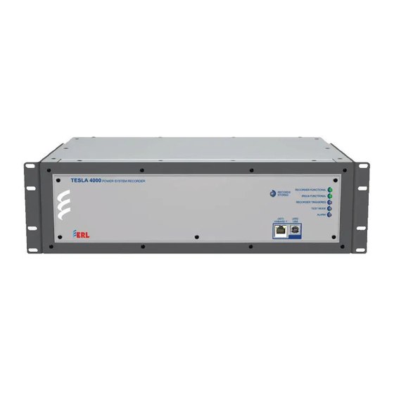
1 Overview 1.3 Front Panel 1. Status LEDs 2. Port 401: Ethernet 3. Port 450: USB Figure 1.2: Front Panel 1.4 Rear Connections Figure 1.3: Rear LAN Port Configuration: Options 0, 1, 2 & 3 TESLA 4000 User Manual D02771R03.01... - Page 21 Figure 1.4: Rear LAN Port Configuration: Option 4 Advanced Non-isolated channels require electrical isolation from the secondary of the PTs and CTs via the external input modules. No direct connec- tion should be made to these inputs. D02771R03.01 TESLA 4000 User Manual...
-
Page 23: Installation And Safety Instructions
If this is not the case then any safety protection pro- vided by the equipment may be impaired. D02771R03.01 TESLA 4000 User Manual... -
Page 24: Physical Mounting
It is 3 rack units (5.25 inches) high and 12.725 inches deep. An additional 3 inches of depth is required for rear connections and cables. A complete me- chanical drawing is shown in “TESLA 4000 Drawings” on page Appendix J-1. To install the relay the following is needed: •... -
Page 25: Case Grounding
3.3 mm² unless otherwise required by local or country wiring reg- ulations. Copper wire is recommended and must be must be low-inductance and as short as possible. #10 Split Washer Washer #10 Hex Nut Ground Stud #10 Terminal Ground Wire Figure 2.5: Protective Earth Connection D02771R03.01 TESLA 4000 User Manual... -
Page 26: Power Supply
One surge protector can be used to protect multiple units as long as the current limit of the surge protection device is not exceeded. Note that this is a consumable item and not covered by ERLPhase warranty. TESLA 4000 User Manual D02771R03.01... -
Page 27: Signal Connections
TESLA is located. Belden 9388, or its equivalent, is an example of an accept- able cable that can be used. D02771R03.01 TESLA 4000 User Manual... - Page 28 All input modules must be grounded via the ground stud on the mod- ule. Re-calibration is required whenever an input module is replaced or moved to a different channel (see “Analog Input Calibration” on page 8-14) TESLA 4000 User Manual D02771R03.01...
- Page 29 DC module channels have a dc to 2 kHz bandwidth, but the bandwidth may be further limited by the recorder’s input filters, depending on the sample rate. Externally mounted resistors set the input type and full scale range. D02771R03.01 TESLA 4000 User Manual...
- Page 30 IRIG-B Time The IRIG-B input provisions on the rear of the unit accepts either modulated Signal or unmodulated IRIG-B time signals, with or without the 1344 extensions. Communication See “Ports” on page 4-1. Ports TESLA 4000 User Manual D02771R03.01...
- Page 31 Alarm Normally inactive red LED that indicates a failure has been detected by the software. The presence of the Alarm LED means much of the system is functioning and can be accessed for diagnosis D02771R03.01 TESLA 4000 User Manual...
-
Page 33: Tesla Control Panel Installation
Installation of TESLA Control Panel software may require changes to your Windows system configuration for proper operation. Please re- view the instructions in this chapter to ensure proper setup. The TESLA 4000 CD-ROM contains the following: • TESLA Control Panel: interface software • Firmware update with installation instructions •... -
Page 34: Installation
5. When the installation is complete, a TESLA Control Panel icon is placed on your desktop. Use the icon to launch Control Panel. If you prefer, you can start Control Panel through Windows Start menu (Start>Programs>ERLPhase>TESLA Control Panel). TESLA 4000 User Manual D02771R03.01... - Page 35 Files (x86)\ERLPhase\TESLA Control Panel\Null_mdm.Inf. Select OK. This is the default location for TESLA Control Panel. If you selected a different location to install TESLA Control Panel, you will find the Null Modem driver (Null_mdm.Inf) in that directory. D02771R03.01 TESLA 4000 User Manual...
- Page 36 7. Select the serial port you wish to use. You are setting up a serial port to be used for a direct cable connection to a TESLA. Typically COM1 or COM2 are available on a PC for this purpose. Select Next. TESLA 4000 User Manual D02771R03.01...
- Page 37 3 TESLA Control Panel Installation Figure 3.3: Select Serial Port 8. Select Finish and close the Phone and Modem Options and Control Panel dialog boxes. D02771R03.01 TESLA 4000 User Manual...
-
Page 38: First Time Start-Up
Note Microsoft Windows security may prevent non-Administrative user accounts from storing data under C:\Program Files(x86); it may be necessary to change the default record and config storage loca- tions for the IEDs. Figure 3.4: Data Location TESLA 4000 User Manual D02771R03.01... -
Page 39: Ports
This chapter describes the ports that are used to communicate with the TESLA 4000. It also describes the communication options available to establish a connection with the TESLA 4000. Port 402 is not available in Model 4003 and hence all communications through port 402 will not be applicable to Model 4003. - Page 40 Spare Parts List” on page Appendix H-1 for optional devices avail- able). When configured with optical network ports, this is a Class I laser product and is considered safe. However, viewing fiber-optic output ports directly is not recommended. TESLA 4000 User Manual D02771R03.01...
-
Page 41: Serial Ports
Direction PC<->IED Pin # on the IED Port Common No connection Notes: IED is DCE, PC is DTE. Pins 1 and 6 are tied together internal to the IED. D02771R03.01 TESLA 4000 User Manual... - Page 42 Pin # on the Modem Adapter Common No connection Notes: IED (with modem adapter) is DTE, modem is DCE. Pins 1 and 6 are tied together internal to the IED. TESLA 4000 User Manual D02771R03.01...
-
Page 43: Irig-B Time Input
SCADA services. Port availability will vary based on selected model configuration parameters. Ethernet LAN Link PC with TCP/IP Port 401 or Port 402 TCP/IP Network Port 401 - RJ-45 Network Port Figure 4.1: Ethernet LAN Link D02771R03.01 TESLA 4000 User Manual... - Page 44 Control Panel are on different subnets. The default setting is 255.255.255.0 • To modify the Default Gateway or Network Mask, go to the Communi- cation > Ethernet screen in TESLA Control Panel. • If unsure of these setting contact your network administrator TESLA 4000 User Manual D02771R03.01...
- Page 45 IED definition. Use the Edit button to view or change this informa- tion. Ensure the Network Link option is selected and the recorder’s IP address is entered. • For details on IED definitions see “Working with TESLA Control Pan- el” on page 6-1. D02771R03.01 TESLA 4000 User Manual...
- Page 46 • A dialog box will appear to show connection progress. • The connection state and the current IED you are connected to is shown on the Windows status bar Figure 4.3: Connect Button Dialog Box TESLA 4000 User Manual D02771R03.01...
- Page 47 To create an USB link between the recorder and the computer, first the USB driver for the ERLPhase 4000 Series Device needs to be installed, as follows: Unzip the file (can be obtained from ERL web site): ERLPhase_USB_driver.zip In this case we assume you unzipped to the Desktop.
- Page 48 • The method of communication with the recorder is specified as part of its IED definition. Use the Edit button to view or change this informa- tion. Ensure the Direct Serial Link option is selected. 4-10 TESLA 4000 User Manual D02771R03.01...
- Page 49 Figure 4.5: Status Bar If the connection fails, check the following: • The communication parameters are the same on both ends (see Step 1 above). • The correct serial port has been selected on your computer. D02771R03.01 TESLA 4000 User Manual 4-11...
- Page 50 • For details on IED definitions see “Working with TESLA Control Pan- el” on page 6-1. 3. Initiate the connection by selecting the Connect button. • A dialog box will appear to show connection progress. 4-12 TESLA 4000 User Manual D02771R03.01...
- Page 51 TESLA recorder. The Edgeport USB Serial Adapter, model # Edgeport/1, from B&B Electronics (www.bbelec.com) is an example of such a device. D02771R03.01 TESLA 4000 User Manual 4-13...
- Page 52 Port 401 or 450 on the recorder, run TESLA Control Panel soft- ware and initiate a connection to the unit. b. When connected, select Utilities in the Main Menu list, and go to the Communication tab to access the Port 405’s settings. 4-14 TESLA 4000 User Manual D02771R03.01...
- Page 53 The factory default for this field is “M1” for external modems. These default values are all that are re- quired for most modems. f. Save your changes, close the Utilities tab and disconnect. D02771R03.01 TESLA 4000 User Manual 4-15...
- Page 54 Modem initialization string is M1 for internal modem. If an internal modem was installed at the factory, it will already be appropri- ately configured. An internal modem option is not available when the ad- vanced communications option is selected. 4-16 TESLA 4000 User Manual D02771R03.01...
- Page 55 The master acts as a gateway to the LAN, providing a route for IP communication between TESLA Control Panel or RecordBase and other TESLA 4000 recorders to the network. Although commonly used as a part of a cooperative group configuration, a gateway modem can also be used simply as a means to communicate with networked recorders.
-
Page 57: Services
5 Services The purpose of this section is to give an overview of the services available on the TESLA 4000. This section uses the term “services” to refer to application level communication protocols providing access to TESLA functions and data. -
Page 58: Scada And Automation Services
5.1 SCADA and Automation Services DNP3 The DNP3 protocol is available on the TESLA 4000 for use with SCADA cli- ent software. DNP3 is available for Ethernet or Serial communication. The DNP3 communication settings and point mapping are configured in TESLA Control Panel. -
Page 59: Interactive User Services
PMU, see Chapter 16 PMU Functionality and Appendix D PMU Standards. 5.2 Interactive User Services TESLA Control TESLA Control Panel (TCP) is the main user interface for the TESLA 4000 recorder. TCP provides a Windows user interface for configuration, metering, Panel (TCP) log management and maintenance. -
Page 61: Working With Tesla Control Panel
When first installed, TESLA Control Panel includes a workspace for a recorder called TESLA 4000 Demo Unit. It contains sample records and configuration files and is configured for network connection with an evaluation unit. - Page 62 Current IED. Forcing a connection with a different re- corder (i.e. moving the serial cable without telling TESLA Control Panel to disconnect), can cause the records and configuration files of that recorder to be mixed with those of the Current IED. TESLA 4000 User Manual D02771R03.01...
-
Page 63: Adding/Editing A Recorder Workspace Definition
We recommend that you use the same name for this workspace as the Unit Name given to the recorder (“Unit Identification” on page 8- Comments User-defined, for your reference only. Location User-defined, for your reference only. D02771R03.01 TESLA 4000 User Manual... - Page 64 The directory where the IED’s retrieved records are stored. Configs Folder The directory where the IED’s configuration files are saved. You can share configuration files and records with other TESLA Con- trol Panel users by using common folders TESLA 4000 User Manual D02771R03.01...
-
Page 65: Online And Offline Operation
• Setup utilities and record configuration screens • Record graphics display • Trend logs • Maintenance functions Connection The Status Bar at the bottom right side of the TESLA Control Panel window Status shows if you are presently online or offline. D02771R03.01 TESLA 4000 User Manual... -
Page 66: Navigating In Tesla Control Panel
Main Menu item. Use the Close button to close the screen. Status Bar The Status Bar at the bottom of the TESLA Control Panel displays the name of the selected recorder workspace and the status of the connections. TESLA 4000 User Manual D02771R03.01... -
Page 67: Metering Display
Angle information displayed on the metering screen may be referenced to any Reference angle reference setting in the configuration file. This feature modifies the dis- play of information on the metering screen and has no impact on recording or communications. D02771R03.01 TESLA 4000 User Manual... - Page 68 The metering display can be exported to another program using Win- dows built-in Alt PrintScreen key and standard paste functions. Phase angle readings displayed in meter groups are based on the configured Phase Angle Reference Channel (see “Phase Angle Ref- erence Channel” on page 9-17). TESLA 4000 User Manual D02771R03.01...
-
Page 69: Recorder Setup
For details on security roles and privileges see “Authentication and Authorization System” on page 17-4. For details on connecting to the recorder using TESLA Control Panel software see “Communicating with the Recorder (IED)” on page 4-5. D02771R03.01 TESLA 4000 User Manual... -
Page 70: Unit Identification
(see “Managing Configuration Files” on page 9-1). Communication Read-only field that displays the version of the communications pro- Version tocol used by the currently connected TESLA unit. TESLA 4000 User Manual D02771R03.01... -
Page 71: Communication Port Settings
8.2 Communication Port Settings The Communication settings control the modes and baud rates of the record- er’s communication ports. The communication port settings are access through the Communication screen on the Serial Tab. Figure 8.3: Serial Communication Setup D02771R03.01 TESLA 4000 User Manual... - Page 72 The Direct/Modem Port refers to either the recorder’s rear panel Port 405 or its (optional) Internal Modem port, depending on the Port Select setting. Direct/Modem Port functionality is not available on all TESLA 4000 IED configurations. Port Select Direct Serial: Port 405 is enabled for a direct serial connection with TESLA Control Panel or a terminal program (to access the Terminal UI).
-
Page 73: Ethernet Configuration
LAN gateway communication. TCP/IP Port Select between ERLPhase IANA Port 7631 or Port 2000. Selection After a setting has been changed, the IED must be manually rebooted in order for the changes to take place. D02771R03.01 TESLA 4000 User Manual... -
Page 74: Recording Control Settings
Edge Recording mode tends to create smaller records that contain useful fault data around the start of the trigger, but may not capture data for the entire du- ration of the trigger. TESLA 4000 User Manual D02771R03.01... - Page 75 Speed and Low Speed data can only be combined during the High Speed data capture portion of the record. Duration Recording mode captures all the data during the fault trigger, but tends to create larger records that may contain unimportant data. D02771R03.01 TESLA 4000 User Manual...
- Page 76 9-56). Continuous Disturbance Recording (CDR) Sample Rate Read-only display of the recording rate in rms samples/second/chan- nel. The rate is configured in the recorders setting file, for details see “Continuous Disturbance Recording” on page 11-1 TESLA 4000 User Manual D02771R03.01...
- Page 77 It’s set as part of the recorder’s configuration (see “TESLA Alarms” on page 9-7). CDR Accumulation This is a read-only indicator set to Recycle when Continuous Distu- bance Recording is enabled. D02771R03.01 TESLA 4000 User Manual...
-
Page 78: Time Display And Settings
Figure 8.7: Recorder Setup Utilities - Time Control Time Sources The TESLA 4000 Power Systems Recorder uses time as the basis of data re- cording and requires the presence of a source time signal on the IED. The re- corder supports the use of modulated or unmodulated IRIG-B time signals... - Page 79 Sets the time display to Universal Coordinated Time (UTC). UTC Offset displayed in Event Log is set to zero. Note that UTC time in snot affected by the Record Time Zone setting or Daylight Savings Time. D02771R03.01 TESLA 4000 User Manual 8-11...
- Page 80 (primary and secondary) for IED synchronization in the absence of an IRIG-B time source. Default configuration for the TESLA 4000 product is for SNTP capabilities to be disa- bled upon start-up. SNTP Poll Interval User configurable parameter for defining SNTP server synchronization time cycle (primary and secondary).
- Page 81 IED. If “Adjust for DST” is selected, and IRIG DST flag is not present, then programmatic DST calculations are en- abled. “IRIG Source is” setting defines if IRIG time of day value is UTC or Lo- cal Time. D02771R03.01 TESLA 4000 User Manual 8-13...
-
Page 82: Analog Input Calibration
If the type of isolation module is changed, for example from a voltage to a cur- rent the readings will be significantly wrong until calibration has been per- formed. Only the channels associated with the altered module need be re-calibrated. 8-14 TESLA 4000 User Manual D02771R03.01... - Page 83 Applied Signal field by more than 10%. This helps to prevent erroneous calibration. If you change the type of isolation module associated with a channel, you must specify the new module type in the input channel's config- uration before calibrating. D02771R03.01 TESLA 4000 User Manual 8-15...
-
Page 84: Notify Recordbase Central Station (Rbcs)
A notification call to RecordBase to trigger swing recordings on other record- Notification ers can be initiated by any of the recorder’s triggers. Cross-trigger notification is selected as part of each channel’s configuration. Figure 8.9: Notify Communication Strategy 8-16 TESLA 4000 User Manual D02771R03.01... - Page 85 The setting can range from 0 (all records) to 3 (highest priority only). Selecting Do Not Notify disables automatic record transfers completely. Record priority is determined by the highest priority trigger included in the record. Trigger priority is set as part of each channel’s configuration. D02771R03.01 TESLA 4000 User Manual 8-17...
-
Page 86: Security Setup
TESLA 4000 see Section 17 Cyber Security. Security Screen The security configuration for the TESLA 4000 is performed on the Security screen. To access the Security screen, the user must login with an account that has “SECADM” privileges. On the initial security setup, use the default “secadmin”... - Page 87 Figure 8.12: View by Role View By Role displays all roles in the right window. Selecting a role displays the user accounts which are assigned that role in the left window. D02771R03.01 TESLA 4000 User Manual 8-19...
- Page 88 (similar to the Add User window) and all account settings can be modi- fied. Contingency Account A Contingency Account for restoring security configuration to factory default is provided. The Contingency Account uses a “Challenge-Response” method for restoring Security Configuration to Factory Defaults. To view the Chal- 8-20 TESLA 4000 User Manual D02771R03.01...
- Page 89 Ethernet LAN. If Remote Firm- ware Update is disabled, users assigned the “Update” role will only have the ability to perform a firmware update with front panel USB (Port 450) connec- tion. D02771R03.01 TESLA 4000 User Manual 8-21...
- Page 90 The Import Security Configuration option allows this security configuration to be imported back to Configuration the IED to restore a previously saved configuration. The exported security con- 8-22 TESLA 4000 User Manual D02771R03.01...
- Page 91 IED reboot. Figure 8.18: Export Security Configuration Default Security The TESLA 4000 is shipped from the factory configured with Default Security Configuration Configuration settings. The Default Security Configuration settings are shown in Table 8.7: Default Security Configuration settings and Table 8.8: Default Settings User Accounts.
- Page 92 VIEWER change VIEWER, OPERATOR, Change@2015 ENGINEER service VIEWER, OPERATOR, Service@2015 ENGINEER, INSTALLER update Update@2015 UPDATE maintenance Maintenance@2015 MAINTENANCE coop Coop@2015 COOPGROUP rbcs Rbcs@2015 COOPGROUP, RCDREADER secadmin Secadmin@2015 SECADM secaudit Secaudit@2015 SECAUD IecFtp ERLPhase2010 INSTALLER 8-24 TESLA 4000 User Manual D02771R03.01...
- Page 93 8 Recorder Setup The view, change and service default user accounts provide users with privilege levels equivalent to the TESLA 4000 firmware versions prior to v2.00. Security The Security Configuration restoration to Factory Defaults is available only to Configuration Terminal User Interface (UI) service. The Terminal UI is accessed using any...
- Page 94 User entered Response is shown in red text. Updating the Challenge To update the Challenge, enter ‘+’ character and press enter. The IED executes operation and prints a new Challenge as shown in Figure 8.21: Challenge up- date example. 8-26 TESLA 4000 User Manual D02771R03.01...
- Page 95 8 Recorder Setup Figure 8.21: Challenge update example D02771R03.01 TESLA 4000 User Manual 8-27...
-
Page 97: Configuring The Recorder
Present Set- tings item in the list or by selecting Present Settings and using the Edit button. This will retrieve the configuration from recorder and displays it in the Config- uration Editor. D02771R03.01 TESLA 4000 User Manual... - Page 98 Saved configuration files can be created, displayed and modified, copied, re- named, deleted or loaded into the recorder. Click the desired configuration from the Saved Settings list, then select the appropriate action button on the TESLA 4000 User Manual D02771R03.01...
- Page 99 The configu- ration can be chosen from a list of the saved settings of the other IEDs defined Configuration in Control Panel. as a Starting Point Figure 9.13b: D02771R03.01 TESLA 4000 User Manual...
-
Page 100: Configuration Editor
To start the editor from the Configuration Manager screen, either double-click on a configuration file or select it and click on the Edit button. The sample screens shown are from the TESLA 4000 Demo configuration. Figure 9.14: TESLA Configuration Editor Navigation Tree The left-side pane of the Configuration Editor window provides a navigation tree to access the various sections of the configuration. -
Page 101: Identification
Manual and are identified in each version’s Release Notes. TESLA 2000 re- corders use Setting Versions 1 through 7. TESLA 3000 Setting Versions start at 201. TESLA 4000 Setting Versions start at 401 to distinguish them from those used by TESLA 3000. - Page 102 Control Panel can always be safely installed. Sample Rate The Sample Rate setting controls the rate at which the TESLA 4000 reads its analog and digital input channels. The setting determines the number of sam- ples per second stored in high speed fault records and used to display calculat- ed high speed channels.
- Page 103 (recycle of stop-when-full) and the level at which to alarm are set in the Recording tab of the Utilities screen (“Record Configuration” on page 8-6. These alarm condition can also be accessed via the SCADA protocols. D02771R03.01 TESLA 4000 User Manual...
-
Page 104: Scada And Dnp Configuration
Note: When parity is set to None and a Modbus protocol is selected, the number of stop bits automatically is set to 2, as per the Modbus standard. Stop Bits (Automatic setting). Always set to 1 stop bit except as noted in Parity setting above. TESLA 4000 User Manual D02771R03.01... - Page 105 Communication > Ethernet screen. Make sure the Master IP Addresses are different from the TESLA IP Address. Port DNP (TCP or UDP) Defines the TCP or UDP port on which the DNP service may be accessed. Usually set to 20000. D02771R03.01 TESLA 4000 User Manual...
- Page 106 Complete details regarding the Modbus protocol emu- lation and data point lists can be found in “Modbus Functions” on page Appendix D-1. Figure 9.16: Communications Setup In Control Panel for Modbus 9-10 TESLA 4000 User Manual D02771R03.01...
- Page 107 Class Data configuration. Complete details regard- ing the DNP3 protocol emulation and data point lists can be found in DNP3 Device Profile on “DNP3 Device Profile” on page Appendix E-1. Figure 9.17: DNP Point Map D02771R03.01 TESLA 4000 User Manual 9-11...
- Page 108 9 Configuring the Recorder Figure 9.18: DNP class data 9-12 TESLA 4000 User Manual D02771R03.01...
-
Page 109: Channels And Triggers
This is the name that will appear beside a channel when it is displayed in a graph or a log. For example the recorder’s Event Log might contain this entry for a change in state of a external input: 2005 Jan 12 20:44:33.672 Line #1.EI.BRKK1_a open. D02771R03.01 TESLA 4000 User Manual 9-13... - Page 110 Type is sufficient to fully identify a channel (e.g. Line #1:Va). In other cases, the Description is required to clarify the channel name. (e.g. You might name an external input channel as “Line #1:EI:BRKR1_a). 9-14 TESLA 4000 User Manual D02771R03.01...
- Page 111 The Element Tree View organizes channels by the element names you create. In the following figure, Element “Line #1” has been expanded to show some of the channels associated with it, such as Va. Figure 9.19: Element Tree View D02771R03.01 TESLA 4000 User Manual 9-15...
- Page 112 You can use this view to gain an overview of channel usage. Although you can chose to work in either view, the Element View is recommended for most operations as it provides an automatic way of grouping related channels. Figure 9.20: Channel Tree View 9-16 TESLA 4000 User Manual D02771R03.01...
- Page 113 All channels use the same reference to provide relative angle calculations. Typically, a phase A voltage channel is used as the ref- erence. D02771R03.01 TESLA 4000 User Manual 9-17...
- Page 114 Channel settings can be edited in the Channel Overview display, pro- viding an alternate way to enter channel settings that helps maintain consistency between channels. The column width can be adjusted on the overview tables to optimize the lay- out for the particular configuration. 9-18 TESLA 4000 User Manual D02771R03.01...
- Page 115 Add Element creates the new element at the end of the present Ele- ment list. Insert Element creates the new element above your current selec- tion. 2. Type the element name and Enter. The typed text replaces the New Element text. D02771R03.01 TESLA 4000 User Manual 9-19...
- Page 116 3. Select the channel number and an input screen appears on the right side. 4. Type in the information required to configure the channel. 5. When you close the screen, you are asked to save the configuration to the recorder. Select Save to Recorder. 9-20 TESLA 4000 User Manual D02771R03.01...
- Page 117 Figure 9.25: Adding Analog Input Channels from the Element Tree Deleting a To remove an channel from the tree, select it and press the <Del> key or right- Channel click and select the appropriate Delete entry from the shortcut menu. D02771R03.01 TESLA 4000 User Manual 9-21...
-
Page 118: Analog Input Channels
SCADA and the long term trending function. TESLA 4000 Power System Recorder input modules are optional and a variety of input modules for voltage and current inputs are available, therefore, you must calibrate the input modules. Refer to “TESLA 4000 PMU Features” on page 16-2 for details on how to calibrate the modules. - Page 119 The list is limited to those modules appropriate for the selected channel type. The module defines input scaling information to the system. View/Set Scale Sets the primary to secondary scale factor. See details below. D02771R03.01 TESLA 4000 User Manual 9-23...
- Page 120 Contacts the RecordBase Central Station when triggered. Can be used to initiate wide area swing recordings and/or automated record transfer (“Notify RecordBase Central Station (RBCS)” on page 8-16) Cross Trigger Activates the cross-trigger contact (#4) to trigger another device. 9-24 TESLA 4000 User Manual D02771R03.01...
- Page 121 Full Scale value, which can be determined from the scaling resistors attached to the module. For dc channels, TESLA uses two-point scaling, whereby the conversion process performs a linear transformation between two points. The secondary values are the default calibration points for the channel. D02771R03.01 TESLA 4000 User Manual 9-25...
- Page 122 The duration of a Sag or Swell is fixed at any value between 0.5 cycle and 1 minute. The duration of a Sag or Swell is fixed at any value between 0.5 cycle and 1 minute. 9-26 TESLA 4000 User Manual D02771R03.01...
-
Page 123: External Input Channels
Number of Up to 64 External Input Channels can be defined, one for each physical input. Channels Types Settings Figure 9.29: External Input Channel Configuration Screen 1.For details see “Model Options” on page 1-5. D02771R03.01 TESLA 4000 User Manual 9-27... - Page 124 36 channel model. Contacts 1 and 4 are reserved for Recorder Functional and Cross-Trigger respectively. Contacts assigned for stor- age alarms or Time sync loss alarm or IEC 61850 communication alarm (“TESLA Alarms” on page 9-7) will not be available for use here. 9-28 TESLA 4000 User Manual D02771R03.01...
-
Page 125: Goose Virtual Input Channels
GOOSE message provided by the publishing IED. Number of Up to 256 GOOSE Virtual Input Channels can be defined. Channels Types Settings Figure 9.30: GOOSE Virtual Input Channel Configuration Screen D02771R03.01 TESLA 4000 User Manual 9-29... - Page 126 Functional and Cross-Trigger respectively. Contacts assigned for stor- age alarms or Time sync loss alarm or IEC 61850 communication fail- ure alarm (“TESLA Alarms” on page 9-7) will not be available for use here. 9-30 TESLA 4000 User Manual D02771R03.01...
-
Page 127: Summation Channel
Low Speed: generates a channel that is phasor sum of the input channels at a rate of one phasor per cycle. Number of 30 Summation Channels are available. Channels Types Specific: Va, Vb, Vc, Ia, Ib, Ic, In (use where appropriate) Generic: Vac, Iac D02771R03.01 TESLA 4000 User Manual 9-31... - Page 128 Identifies the channels to be used in the summation. The available list Input 3 includes all previously defined analog channels and any summation channel with a lower summation index number. The list grows auto- matically as you define new channels. 9-32 TESLA 4000 User Manual D02771R03.01...
- Page 129 Functional and Cross-Trigger respectively. Contacts assigned for stor- age alarms or Time Sync loss alarm or IEC 61850 communication fail- ure alarm (“TESLA Alarms” on page 9-7) will not be available for use here. D02771R03.01 TESLA 4000 User Manual 9-33...
-
Page 130: Sequence Component Channels
12 Sequence Component Channels are available. Channels Types Vseq, Iseq Notes The primary to secondary scale factor used by the Sequence Component Chan- nel is the same as that of the selected Phase A channel. 9-34 TESLA 4000 User Manual D02771R03.01... - Page 131 (voltage or current) and includes analog input or summation channels which have already been defined. The list grows automatically as you define new chan- nels. Trigger Settings D02771R03.01 TESLA 4000 User Manual 9-35...
- Page 132 Functional and Cross-Trigger respectively. Contacts assigned for stor- age alarms or Time Sync loss alarm or IEC 61850 communication fail- ure alarm (“TESLA Alarms” on page 9-7) will not be available for use here. 9-36 TESLA 4000 User Manual D02771R03.01...
-
Page 133: Impedance Channels
Low Speed: Impedance magnitude at a rate of one value per cycle. Number of 18 Impedance Channels are available. Channels Types Z1 (impedance) Notes The impedance magnitude and angle readings are also available to the meter- ing display, SCADA and the long term trending function. D02771R03.01 TESLA 4000 User Manual 9-37... - Page 134 0.5 cycle increments. For example, for a 1.5 ROC setting, TESLA compares previous 1.5 cycle window to the current 1.5 cycle window and checks if ROC condition is met. Setting range is 0.5 to 8.0 cycles. 9-38 TESLA 4000 User Manual D02771R03.01...
- Page 135 Functional and Cross-Trigger respectively. Contacts assigned for stor- age alarms or Time Sync loss alarm or IEC 61850 communication fail- ure alarm (“TESLA Alarms” on page 9-7) will not be available for use here. D02771R03.01 TESLA 4000 User Manual 9-39...
-
Page 136: Watts And Vars Channels
The primary to secondary scale factor used by the Watts/Vars Channel is based on those of its voltage and current input channels. Watts, Vars, and Volt-Amp magnitudes are also available to the metering dis- play, SCADA and the long term trending function. 9-40 TESLA 4000 User Manual D02771R03.01... - Page 137 Watts 3 for each Watts Detector is measured. 0.5 to 8.0 cycles. Vars Period of time over which both positive and negative rate of change for Var Detector is measured. 0.5 to 8.0 cycles. D02771R03.01 TESLA 4000 User Manual 9-41...
- Page 138 Functional and Cross-Trigger respectively. Contacts assigned for stor- age alarms or Time Sync loss alarm or IEC 61850 communication fail- ure alarm (“TESLA Alarms” on page 9-7) will not be available for use here. 9-42 TESLA 4000 User Manual D02771R03.01...
-
Page 139: Frequency Channels
Low Speed: Frequency measurements at a rate of one value per cycle. Number of 2 Frequency Channels are available. Channels Types Freq Notes Frequency channels are not associated with particular Elements. Their names are fixed as Frequency 1 and Frequency 2. D02771R03.01 TESLA 4000 User Manual 9-43... - Page 140 0.0333 (2 cycles) to 1,200 seconds in half-cycle incre- ments. Trigger Actions Enable Enables or disables the associated trigger. A trigger can be disabled without altering the rest of its settings. Fault Initiates a fault (high speed) recording when triggered. 9-44 TESLA 4000 User Manual D02771R03.01...
- Page 141 36 channel model. Contacts 1 and 4 are reserved for Recorder Functional and Cross-Trigger respectively. Contacts assigned for stor- age alarms or Time Sync loss alarm or IEC 61850 communication failure alarm (“TESLA Alarms” on page 9-7) will not be available for use here. D02771R03.01 TESLA 4000 User Manual 9-45...
-
Page 142: Logic Functions
30 Logic Functions are available. Channels Types Logic Notes The output of the Logic functions is available to the metering display, SCADA and the long term trending function. Settings Figure 9.36: Logic Function Configuration 9-46 TESLA 4000 User Manual D02771R03.01... - Page 143 Specifies the priority to be assigned to records created by this trigger. The priority is used to determine Central Station notification. 1 - 3 (3 is the highest priority). (“Notify RecordBase Central Station (RBCS)” on page 8-16). D02771R03.01 TESLA 4000 User Manual 9-47...
- Page 144 36 channel model. Contacts 1 and 4 are reserved for Recorder Functional and Cross-Trigger respectively. Contacts assigned for stor- age alarms or Time Sync loss alarm or IEC 61850 communication failure alarm (“TESLA Alarms” on page 9-7) will not be available for use here. 9-48 TESLA 4000 User Manual D02771R03.01...
-
Page 145: Fault Locator Functions
0% to 120% forward reach of the circle and calculated distance is less than the line length. The lowest impedance within the pick-up zone between Zan, Zbn, Zcn, Zab, Zbc and Zca is used to calculate the fault location. D02771R03.01 TESLA 4000 User Manual 9-49... - Page 146 Log identifying the time, the Element, the faulted type (e.g. A-B, B-G...) and the distance to fault. The output of the Fault Locator Function is available through SCADA. It can- not be metered or trended. 9-50 TESLA 4000 User Manual D02771R03.01...
- Page 147 Any External Input Channel, GOOSE Virtual Input Channel or trigger detector from any other channel or function. Note that the initiating Event typically requires a 1.5 cycle delay to obtain accurate fault loca- tion information. D02771R03.01 TESLA 4000 User Manual 9-51...
-
Page 148: Power Factor Functions
Recording Power Factor Functions are not recorded. Number of 18 Power Factor Functions are available. Channels Types Notes Power factor readings are available to the metering display, SCADA and the long term trending function. 9-52 TESLA 4000 User Manual D02771R03.01... - Page 149 Settable from 1 to 10,000 seconds in 1 second increments. Trigger Action Enable Enables or disables the associated trigger. A trigger can be disabled without altering the rest of its settings. Fault Initiates a fault (high speed) recording when triggered. D02771R03.01 TESLA 4000 User Manual 9-53...
- Page 150 Functional and Cross-Trigger respectively. Contacts assigned for stor- age alarms or Time Sync loss alarm or IEC 61850 communication fail- ure alarm (“TESLA Alarms” on page 9-7) will not be available for use here. 9-54 TESLA 4000 User Manual D02771R03.01...
-
Page 151: Meter Groups
Phase angle readings displayed in meter groups are based on the configured Phase Angle Reference Channel “Phase Angle Refer- ence Channel” on page 9-17. D02771R03.01 TESLA 4000 User Manual 9-55... -
Page 152: Trend Logging
Use the tree’s expansion buttons to locate the desired channel, then drag and drop your selection on the grid. 9-56 TESLA 4000 User Manual D02771R03.01... - Page 153 If you wish to have the long-term event log without trending any data, define a trend without any channels in it. A daily limit of 1000 events can be stored in the trend log. D02771R03.01 TESLA 4000 User Manual 9-57...
-
Page 154: Printing
(see “DNP3 Device Profile” in Appendix F) Selecting the Print DNP settings item from the File menu generates a listing that is configurable - listing the full function names in Element-Function-Description format along with the equiv- alent DNP points. 9-58 TESLA 4000 User Manual D02771R03.01... - Page 155 9 Configuring the Recorder You can preview the printed output by selecting Print DNP Preview from the File menu. Print DNP function is also available under the Config menu. D02771R03.01 TESLA 4000 User Manual 9-59...
-
Page 157: Record And Log Management
Record Filter. Note that if additional recordings are created through the Trigger Fault, Trigger Swing or Trigger Both buttons, these new records do not displace the earliest fetch/displayed file records in the tree. D02771R03.01 TESLA 4000 User Manual 10-1... - Page 158 IED. Get from IED The Get From IED and Delete button erases the records on the recorder after and Delete they have been transferred to Control Panel and verified. 10-2 TESLA 4000 User Manual D02771R03.01...
- Page 159 Recordings directory. You may then perform whatever command is appropriate for the selection set, such as a Get from IED or a Get and Delete from IED Command. D02771R03.01 TESLA 4000 User Manual 10-3...
-
Page 160: Trend Log
Events The Events section of the display shows all the events recorded during the pe- riod of interest set with the range of dates 10-4 TESLA 4000 User Manual D02771R03.01... - Page 161 Print Events The list of events in the Events portion of your screen is printed. D02771R03.01 TESLA 4000 User Manual 10-5...
-
Page 162: Event Log
The general format for event message is: Line# Date/Time UTC Offset Station ID Unit ID EventDescription Examples of Event Messages can be seen above in Figure 10.3: Event Log Dis- play. 10-6 TESLA 4000 User Manual D02771R03.01... - Page 163 Removes all events from remote IED. Print Prints all the events (up to 500 events) to a local printer. Export to CSV Exports the event list to CSV format to a user-selected file location. D02771R03.01 TESLA 4000 User Manual 10-7...
-
Page 164: Audit Trail
Save to File The Save to File option allows for saving of the current Audit Trail to csv for- mat. Refresh The Refresh button updates the Audit Trail to display any new security alarms or events. 10-8 TESLA 4000 User Manual D02771R03.01... -
Page 165: Continuous Disturbance Recording
Data Reporting 2. Standard PRC-002-1 – Define Regional Disturbance Monitoring and Re- porting Requirements The CDR feature incorporated in the TESLA 4000 Recording System meets and exceeds the requirements of NERC Standards as represented in the follow- ing table. Table 11.1: NERC Standards... - Page 166 - a maximum of 36 channels can be se- lected. 1.For details see “Model Options” on page 1-5 11-2 TESLA 4000 User Manual D02771R03.01...
- Page 167 Period der, expanding the TESLA 4000 unit system memory for increased file/record storage capacity (not available in Model 4003). If TESLA 4000 firmware with continuous disturbance recording support is installed on a unit without the des- ignated continuous disturbance recording partition, continuous disturbance re- cording will be disabled.
- Page 168 Length for the requested record. These fields are pre-filled with a time Request that is computed from the To time minus the initial Length value. Graph Launch RecordGraph with the selected record or records. 11-4 TESLA 4000 User Manual D02771R03.01...
- Page 169 The command Safe Shutdown Mode is available only at the service access lev- el for TESLA Control Panel or via Port 450 login for maintenance utilities. When the command Safe Shutdown Mode is used, all TESLA 4000 application tasks are stopped ensuring all accumulated data are written out to the flash drive, all open files are closed and the file system status is updated.
- Page 170 All accumulated continuous disturbance recording data is discarded every time Configuration new settings with modified continuous recording configuration are loaded on TESLA 4000. Continuous recording configuration includes sample rate, ana- Changes log input configuration, continuous recording channel selection and order.
-
Page 171: Graphing Records
RecordGraph. 5. Click the Graph button. Figure 12.1: Launching RecordGraph from TESLA Control Panel When the Graph button is clicked from the TESLA Control Panel, Record- Graph is launched with the selected record. D02771R03.01 TESLA 4000 User Manual 12-1... - Page 172 2. Select the record from the list. To select multiple records, press Ctrl key and click on the desired records. 3. Select the Graph button at bottom of screen. Figure 12.2: Display Trend Records 12-2 TESLA 4000 User Manual D02771R03.01...
-
Page 173: Record Export Utility
PTI version 1 or version 2 formats. Excel (CSV) TESLA records can be exported in basic comma separated values (also known as comma-delimited) ASCII format suitable for importing into standard tools such as Microsoft Excel. D02771R03.01 TESLA 4000 User Manual 13-1... - Page 174 2. Select a local record from the record list. 3. Select the Export button to launch the Export window. 4. Select the desired export output format and select OK. Figure 13.1: Select Export File Type 13-2 TESLA 4000 User Manual D02771R03.01...
-
Page 175: Comtrade Format
The Header Text field contains the text written into the COMTRADE header (.hdr) file. By default, the field contains the Location, Name, Number and the Unit ID of the unit that produced the record. This text can be modified, deleted or extended as desired. D02771R03.01 TESLA 4000 User Manual 13-3... - Page 176 Delete a channel from the Exported Channel list box. << Delete all channels from the Exported Channel list box. Offset negative start When checked, this option shifts the negative time to start from times to begin at zero zero. 13-4 TESLA 4000 User Manual D02771R03.01...
-
Page 177: Pti Format
The Version field lets you select between PTI version 1 and version 2. Please refer to PTI documentation for details on the differences of these versions. Format Only ASCII format output files are available. Format ASCII is the only format option for PTI. D02771R03.01 TESLA 4000 User Manual 13-5... - Page 178 Delete a channel from the Exported Channel list box. << Delete all channels from the Exported Channel list box. Offset negative start times When checked, this option shifts the negative time to start from to begin at zero zero. 13-6 TESLA 4000 User Manual D02771R03.01...
-
Page 179: Excel (Csv) Format
There is no header text written to the Excel CSV format output file. Version There are no version options for the Excel CSV output. Format ASCII is the only format options for the Excel CSV output. D02771R03.01 TESLA 4000 User Manual 13-7... - Page 180 Delete a channel from the Exported Channel list box. << Delete all channels from the Exported Channel list box. Offset negative start times When checked, this option shifts the negative time to start from to begin at zero zero. 13-8 TESLA 4000 User Manual D02771R03.01...
-
Page 181: Ieee C37.232 Tsd File Naming
Figure 13.5: Time Sequence Data (TSD) Record Settings Feature activation allows local TSD Record names to be toggled between ER- LPhase proprietary and C37.232 file naming structures. This does not affect re- cords currently stored on the IED. D02771R03.01 TESLA 4000 User Manual 13-9... - Page 182 13 Record Export Utility Figure 13.6: IEEE C37.232 Filename Conversion Feature 13-10 TESLA 4000 User Manual D02771R03.01...
-
Page 183: Cooperative Recorder Group
14 Cooperative Recorder Group A cooperative recorder group combines the easy-to-use interface of a single TESLA 4000 recorder with the recording ability of up to four recorders. A co- operative recorder group consists of two to four TESLA 4000 recorders work- ing together to form a larger virtual recorder. - Page 184 If the record was captured by the recorder it can still be retrieved and viewed as a single record from the individual recorder using standard (i.e. non- cooperative mode) methods. 14-2 TESLA 4000 User Manual D02771R03.01...
- Page 185 For further details on cooperative group records, see “Working With Records From a Cooperative Recording Group” on page 14-13. RecordBase RecordBase Central Station v2.0 and above can work with a TESLA 4000 co- Central Station operative recording group. RecordBase can: •...
-
Page 186: Setting Up A Cooperative Recording Group
14 Cooperative Recorder Group 14.2 Setting Up a Cooperative Recording Group Figure 14.1: Cooperative Recording Group with Remote Access 14-4 TESLA 4000 User Manual D02771R03.01... - Page 187 These steps are covered in detail in the following sections. A cooperative group must only include recorders from the same gen- eration (4000, 4003, 3000). A TESLA 4000 cooperative group can not include a mix of recorder types; it must be made exclusively of TESLA 4000s.
- Page 188 Communication Menu in TESLA Control Panel via the Ethernet tab. A note on PPP addresses: TESLA 4000 uses 3 pairs of IP addresses for its PPP (point to point protocol) communication; one for the front USB port, one for the rear serial / modem port, and one for communication with Re- cordBase Central Station.
- Page 189 Any information in the corre- sponding fields of the IED Definition will be overwritten and saved if you exit with OK. These values are configured on the recorder as part of its Unit Identification. D02771R03.01 TESLA 4000 User Manual 14-7...
- Page 190 Recorder cover this in detail. Important Certain settings must be the same on all recorders for cooperative mode to function correctly. See “Required Cooperative Mode Set- tings” on page 14-14 for the list. 14-8 TESLA 4000 User Manual D02771R03.01...
- Page 191 “ENGINEER” or “UPDATE” roles in order to configure and save the Cooperative Mode setup. For more details regarding user se- curity roles and rights, see “Authentication and Authorization System” on page 17-4. D02771R03.01 TESLA 4000 User Manual 14-9...
- Page 192 Location Should be the name and/or location of the Substation. IED Serial Number blank Model Must be TESLA 4000 – Cooperative. IP Address Blank Communication Must be Connect Through IED with the Master Recorder specified. 2. Select the cooperative recording group members.
- Page 193 75 seconds. Figure 14.2 shows all members are connected to each other. If a proper connection has not been established, alter- nate messages such as “connected to” or “connected from” are dis- played in the status fields. D02771R03.01 TESLA 4000 User Manual 14-11...
- Page 194 Ethernet switch. Alternatively, a di- rect serial connection with each recorder can be used. (You may need to alter the Communication mode settings in a recorder's IED Definition). 14-12 TESLA 4000 User Manual D02771R03.01...
-
Page 195: Working With Records From A Cooperative Recording Group
Calculated channels are automatically generated when the records are trans- ferred to TESLA Control Panel. This differs from individual recorder records where calculated channels are generated when the record is first displayed by RecordGraph. D02771R03.01 TESLA 4000 User Manual 14-13... -
Page 196: Required Cooperative Mode Settings
Record Length recorder to automatically extend a extension (Maximum Record recording to include subsequent Length > Normal Record Length) triggers is automatically added to avoid multiple overlapping records in the case of near-coincident triggers. 14-14 TESLA 4000 User Manual D02771R03.01... - Page 197 Sample Rate Records with a sample rate differ- Setting must be the same on all ent from that of the Master group members Recorder’s record will be left out of the combined record group D02771R03.01 TESLA 4000 User Manual 14-15...
-
Page 199: Recorder Health Monitoring And Maintenance
• Post-failure recovery The hardware watchdog continuously monitors the behavior pattern of the su- pervisory software. Self-Recovery The TESLA 4000, when not in its normal operating state, can be in one of the Procedure following states: • Software restart • Hardware restart •... - Page 200 Recorder’s The recorder states are listed in the section Self-Recovery Procedure list above. State Indication The TESLA 4000 recorder has the following features to indicate its state and to deliver IED status warnings: • Recorder Inoperative output contact • Front Panel Recorder Functional LED •...
-
Page 201: Maintenance Functions And Diagnostic Tools
TESLA Control Panel longer to establish connection to a recorder in Diagnostic the Alarm (inoperative) state. Tools To log in to the IED, use the default maintenance account provided with the TESLA firmware or use any customized user account with the “MAINTE- NANCE” role. D02771R03.01 TESLA 4000 User Manual 15-3... - Page 202 See “Authentication and Authorization System” on page 17-4 for information on user accounts and Roles. An example of TESLA Control Panel Main Menu with Maintenance access is shown in Figure 15.3: Main Menu with Mainte- nance access. 15-4 TESLA 4000 User Manual D02771R03.01...
- Page 203 Memory tab status. memory status. maintenance Recover IED that reports tools Storage Memory issue. Network IED Network Troubleshoot network Troubleshoot network diagnostic Utilities tab communication issues. communication issues. tools Assess network traffic going through recorder. D02771R03.01 TESLA 4000 User Manual 15-5...
- Page 204 The "Save As" dialog provides interface to modify the diagnostics file name if desired, though it is preferable to keep the date and time sections of the diagnostics file name as created by IED. Figure 15.4: System Diagnostics tab. 15-6 TESLA 4000 User Manual D02771R03.01...
- Page 205 Default Setup, as described above, plus recorder’s default calibration. Storage The Storage Memory tab provides controls to select and execute a storage memory maintenance command and displays IED’s report after the execution Memory of selected command. D02771R03.01 TESLA 4000 User Manual 15-7...
- Page 206 This command reinitializes the file system of the CDR data Storage. All CDR data will be lost after command execution. Activate Record storage This command verifies new record storage replacement device and ensures its compatibility with the current recorder’s firmware. 15-8 TESLA 4000 User Manual D02771R03.01...
- Page 207 Memory. Please put recorder in the Safe Shutdown state before turn- ing off or disconnecting its power supply. Refer to “Safe Shutdown Mode” on page 11-5 for information on the recorder’s safe shutdown procedure. D02771R03.01 TESLA 4000 User Manual 15-9...
- Page 208 Modification of the PPP IP addresses may be required only when the troubleshooting recorder’s default PPP IP addresses conflict with the actual LAN IP addresses in use. The PPP IP Addresses tab allows for viewing and modification of the record- er’s PPP configuration. 15-10 TESLA 4000 User Manual D02771R03.01...
- Page 209 • All PPP IP addresses must be on a different network than the recorder’s LAN/WAN. TESLA Control Panel enforces these three conditions and will not allow the user to save an invalid configuration. Figure 15.8: PPP IP Addresses tab D02771R03.01 TESLA 4000 User Manual 15-11...
-
Page 211: Pmu Functionality
C37.118 standard. An SNTP time synchronization source is not recommended for PMU applications. The PMU module is a standard feature on the TESLA 4000. The PMU func- tionality complies with the IEEE C37.118 - 2005 and 2011 (amended in 2014) standard for Synchrophasors for Power Systems. -
Page 212: Tesla 4000 Pmu Features
16 PMU Functionality 16.2 TESLA 4000 PMU Features Phasor The PMU functional module estimates the phasor using the DFT algorithm, as- Estimation suming the IED is receiving an IRIG-B signal from a reliable GPS receiver as per the C37.118 standard. The phasor magnitude and phase angle, once esti- mated, is compensated for the frequency variation over a wide range, covering the requirements specified in the C37.118 standards. - Page 213 Table 16.1: Unit Codes for Analog Data Code Unit kvar Mvar ohms degrees Digital Status There are up to 32/64 digital (contact) channels per TESLA 4000 recorder that Data can be streamed to a remote PDC (Phasor Data Concentrator). D02771R03.01 TESLA 4000 User Manual 16-3...
- Page 214 TVE (total vector error) enters and stays in the specified accuracy zone correspond- ing to the compliance level (as per the standard selected). PMU Accuracy Total Vector Error: (TVE) according to the standard selected. 16-4 TESLA 4000 User Manual D02771R03.01...
- Page 215 This is available on the CD titled TESLA 4000. Calibration The TESLA 4000 Power System Recorder has a variety of optional input mod- ules for voltage and/or current available, therefore, you must calibrate the input modules. The PMU calibration requires both the magnitude and phase angle calibration at nominal signal level.
- Page 216 PMU phasor configuration. Phase an- gle calibration is required when ever the input module and / or the TESLA recorder sample rate are changed and also recommended when the PMU stan- dard selected is changed. 16-6 TESLA 4000 User Manual D02771R03.01...
-
Page 217: Communication With The Pmu
Either modem is usable for either role. Connect to a TESLA unit and click on the Communication > PMU tab. Usually PMU data is transmitted through the Ethernet (copper or fiber). Figure 16.3: PMU communication setup screen D02771R03.01 TESLA 4000 User Manual 16-7... - Page 218 = 57600 bit/s, 20 f/s is the maximum setting without failing. 2. For the maximum stream rate = 60 frames/second: at baud rate = 57600 bit/s, the maximum number of phasors can be supported without failing is 18. 16-8 TESLA 4000 User Manual D02771R03.01...
- Page 219 • Number of PDC Clients: This option allows user to set the number of DC clients that can connect to the recorder simultaneously. This option is con- figurable only if the Mode is Network (TCP). TESLA 4000 recorder sup- ports up to two dc clients.
-
Page 220: Pmu Configuration
After you check the PMU Module, select OK to accept the changes, then select the Configuration option to open the configuration view. Select an existing configuration file by double-clicking on the file and the following screen ap- pears. 16-10 TESLA 4000 User Manual D02771R03.01... - Page 221 Right-click on the Channel Group1 to display the choice to add a PMU as shown below. Figure 16.6: Invoking PMU configuration through right-click menu and select Angle Reference to PMU(GPS,1PPS) Select the PMU choice and the following screen appears allowing you to select the Phasors. D02771R03.01 TESLA 4000 User Manual 16-11...
- Page 222 PMU definition screen for streaming to the PDC. Analog, PMU and Frequency data formats may be user configured to provide information in In- teger or Floating-Point form. 1.For details see “Model Options” on page 1-5. 16-12 TESLA 4000 User Manual D02771R03.01...
- Page 223 PMU data will not be transmitted, even though the other parameters are available. You must select at least one 1.For details see “Model Options” on page 1-5. D02771R03.01 TESLA 4000 User Manual 16-13...
- Page 224 Data Concentrator. Note that the saved PMU configuration is automatically used in the PMU me- tering display, when this file is loaded on the TESLA 4000 DFR. Use Save/Close option to save the PMU information in the setting file for later retrieval and/or loading into TESLA 4000 DFR.
-
Page 225: Pmu Metering
10th user-defined metering group. This means, if the setting file already has 10 user-defined Metering groups, the PMU metering replaces the last (10th) me- tering group. Hence the total number of user-defined Metering groups avail- able will be 9 instead of 10. D02771R03.01 TESLA 4000 User Manual 16-15... -
Page 227: Cyber Security
Security Reference Documents on page 17-11. 17.1 Ports and Services Table 5.6 on page 5-1 shows a list of Services supported by the TESLA 4000. This table also shows which services can be enabled or disabled. There are two groups of services: •... - Page 228 • contain at least one numerical character; • contain at least one special character; • enforce minimum Password length (8 to 20 characters). See “Password Complexity” on page 8-22 for details on configuring the Pass- word Complexity Rules. 17-2 TESLA 4000 User Manual D02771R03.01...
- Page 229 The IED keeps track of failed logins by associating a failed logins counter with each User. The User is locked out when counter reaches the “Maximum re- D02771R03.01 TESLA 4000 User Manual 17-3...
-
Page 230: Authentication And Authorization System
The Account system is used for all types of interactive User services. The Ac- count system is stored locally on IED. There are two types of accounts: • Multi-purpose User Accounts • Contingency Account for Security Configuration recovery to factory de- faults. 17-4 TESLA 4000 User Manual D02771R03.01... - Page 231 A Role Based Access Control (RBAC) model is used for User authorization. Mechanism User Accounts Number of User Accounts The TESLA 4000 supports up to 32 User Accounts. Account Properties The properties associated with the User Accounts are shown in Table 17.2 Ac- count Properties Table 17.2: Account Properties...
- Page 232 Configuration restoration operation. Alternatively, the User can trigger a Chal- lenge update manually at any time. Challenge update is available in the Secu- rity Configuration “Contingency Account” dialog or Terminal UI dialog (see “Default Security Configuration Settings” on page 8-23 for more details). 17-6 TESLA 4000 User Manual D02771R03.01...
- Page 233 Can read and change security configuration SECAUD Can read and download audit trail log TESLA 4000 default User Roles MAINTENANCE Can perform Tesla 4000 maintenance functions UPDATE Can perform Tesla 4000 firmware update RCDREADER Can access Tesla 4000 record storage COOPGROUP Role is designated for the inter-Tesla COOP mode communication.
- Page 234 Read IED settings file Load settings file to IED Read communication configuration Change communication configuration View IED time Read time configuration Change time and time configuration Calibrate Update firmware Read/download system diagnostics Restore default configuration 17-8 TESLA 4000 User Manual D02771R03.01...
-
Page 235: Security Notification System
• A Security Alarm is an alert related to an unauthorized activity or an activ- ity critical to the operation of the IED The Security Notification types are shown in Table 17.5 Security Notification Types. D02771R03.01 TESLA 4000 User Manual 17-9... - Page 236 Audit Trail cannot be reset or erased and individual records cannot be deleted. The validity of each record is protected by a signature. Access to Audit Trail is available via TESLA Control Panel (see “Audit Trail” on page 10-8). 17-10 TESLA 4000 User Manual D02771R03.01...
-
Page 237: Cyber Security Reference Documents
[3] IEEE Std 1686-2013 IEEE Standard for Intelligent Electronic Devices Cy- ber Security Capabilities [4] IEC/TS 62351-8 Power systems management and associated exchange – Data and communications security – Part 8: Role-based access control [5] Tesla 4000 Security Notification System User Guide v1.0 D02771R03.01 TESLA 4000 User Manual 17-11... -
Page 239: Appendix A Specifications
Pollution Degree 2 Ingress Protection IP30 standard Insulation Class Class I Weight TESLA 4000 18 channel: 16.7 lbs (7.6 kg) TESLA 4000 36 channel: 17.8 lbs (8.1 kg) Dimensions 3U high (5.25"), 19" wide, 12.725" deep Rack mount Nominal Frequency... - Page 240 Appendix A Specifications TESLA 4000 Power System Recorder Record Storage Standard Capacity with 4GB flash up to 1000 2-sec- ond fault records with all 36 channels sampled at 96 samples/cycle channels or a combination of fault and swing records. Extended Capacity flash up to 1000 5-second fault...
- Page 241 Appendix A Specifications TESLA 4000 Power System Recorder Continuous Disturbance Recording (CDR) Continuous Disturbance 6 to 60 RMS records/second for up to 36 channels Can store from 10 to 140 days of continu- Recording (CDR) ous records. Standard Capacity min. 10 days data retention below 30 RMS records/second on all 36 channels.
- Page 242 Appendix A Specifications TESLA 4000 Power System Recorder Inputs and Outputs Remote Analog Input 4 input current module, 3 or 4 input voltage module Modules mount on DIN rail (35mm Modules or 4 input dc isolation module and split-core CTs.
- Page 243 Appendix A Specifications TESLA 4000 Power System Recorder Voltage Dips, Interrup- IEC 6100-4-11, IEC 60255-11 200 ms Interrupt tions, Variations Conducted RF Immunity IEC 61000-4-6 Level 3, IEC 60255-22-6 Level 3 Radiated RF Susceptibility IEC 61000-4-6 Level 3, IEC 60255-22-3 Level 3...
- Page 244 Appendix A Specifications TESLA 4000 Power System Recorder Detailed Environmental Tests Description Test Test Level Type Test Test Points IEC/EN 60068-2-1 Cold Temperature -40C for 16 hours IEC/EN 60068-2-2 Hot Temperature 85C for 16 hours IEC/EN 60068-2-30 Humidity Cycle 55C/93% RH and 25C/95%...
- Page 245 Appendix A Specifications TESLA 4000 Power System Recorder Detailed Environmental Tests IEC/EN 61000-4-11 Voltage Dips & Interrupts Power Port – AC applied 40% for 10/12 cycles, 70% for IEC/EN 61000-4-29 10/12 cycles, 100% for 250/ 300 cycles IEC 60255-11 Voltage Dips & Interrupts Power Port –...
-
Page 247: Appendix B Tesla Hardware Description
Flash. Extended capacity options are available and may vary according to specifications. Front Panel The Front Panel Board provides visual indication of the status of the TESLA Board recorder and USB and network ports. 1.For details see “Model Options” on page 1-5. D02771R03.01 TESLA 4000 User Manual Appendix B-1... -
Page 249: Appendix C Glossary
Cooperative Recording A set of TESLA 4000 recorders that work together to form a larger virtual recorder. Group DC Input Module An external input module that can be scaled to accept a wide range of voltage or current signals. - Page 250 A situation that can initiate a recording. Universally Coordinated Time. Approximately equivalent to Greenwich Mean Time (GMT). A universal time maintained by time standards bodies worldwide. All local times are expressed as an offset from UTC. Appendix C-2 TESLA 4000 User Manual D02771R03.01...
-
Page 251: Appendix D Pmu Standards
Appendix D PMU Standards Appendix D PMU Standards The PMU functionality in the TESLA 4000 complies with the IEEE C37.118-2005 and 2011 (amended in 2014) Standards for Synchropha- sor for Power Systems. The compliance results for both 50Hz and 60Hz systems are summarized below. -
Page 252: Ieee C37.118.1A - 2011 Standards (Amended In 2014: C37.118.1A
(THD) 0.050- 50th 0.048 None None 1.018/ Out of band < 0.2% of 10 % of input signal 1.033 interference input signal magnitude for s ≥ magnitude 10. No requirement s < 10. Appendix D-2 TESLA 4000 User Manual D02771R03.01... - Page 253 ≤ 20 Out-of- < 0.2 % of Range: No requirements Range: Interfering signal 10 % of signal band input signal magnitude interferenc magnitude None None None None 0.01 Hz 0.003 None None D02771R03.01 TESLA 4000 User Manual Appendix D-3...
- Page 254 0.002 0.061 0.192 10.41 0.06 0.30 0.015 1.56 0.06 0.011 1.45 0.30 min( min( Formulas /10.2) 0.03 × 0.18 × π × 5.5) 0.06 × 0.18 × π × Appendix D-4 TESLA 4000 User Manual D02771R03.01...
- Page 255 Results Std. Results base angle require require require require 50/60Hz 50/60Hz 50/60Hz 50/60Hz ments ments ments ments 0.009/ 0.083/ 0.01 Hz 0.001/ 0.4 Hz/ 0.392/ 0.01 Hz 0.2 Hz/ 0.008 0.053 0.001 0.201 D02771R03.01 TESLA 4000 User Manual Appendix D-5...
- Page 256 14/ 4.5/ 0.086/ 0.017/ Greater 0.04879 Greate 0.047/ Phase test as in Same as in of 14/Fs r of 0.058 0.049 0.033 Table 8 Table 8 or 14/f0 14/Fs 0.121 or 14/ Appendix D-6 TESLA 4000 User Manual D02771R03.01...
- Page 257 130 ms (for 50 Hz, 50fps) 108.3 ms (for 60 Hz, 60 fps) Note: Latency is limited by the need to include at least one cycle of the power system waveform for synchrophasor calculation. D02771R03.01 TESLA 4000 User Manual Appendix D-7...
-
Page 259: Appendix E Modbus Functions
1: On (active) Logic Detector 17 00785 0: Off (inactive) 1: On (active) Logic Detector 18 00786 0: Off (inactive) 1: On (active) Logic Detector 19 00787 0: Off (inactive) 1: On (active) D02771R03.01 TESLA 4000 User Manual Appendix E-1... - Page 260 1: On (active) External I/P 17 10017 0: Off (inactive) 1: On (active) External I/P 18 10018 0: Off (inactive) 1: On (active) External I/P 19 10019 0: Off (inactive) 1: On (active) Appendix E-2 TESLA 4000 User Manual D02771R03.01...
- Page 261 1: On (active) External I/P 57 10057 0: Off (inactive) 1: On (active) External I/P 58 10058 0: Off (inactive) 1: On (active) External I/P 59 10059 0: Off (inactive) 1: On (active) D02771R03.01 TESLA 4000 User Manual Appendix E-3...
- Page 262 0: Off (no change) 1: On (change) External I/P 34 Change latch 10290 0: Off (no change) 1: On (change) External I/P 35 Change latch 10291 0: Off (no change) 1: On (change) Appendix E-4 TESLA 4000 User Manual D02771R03.01...
- Page 263 Tesla Clock Time (UTC). Read all in same query to ensure consistent time reading data Milliseconds Now 40001 * Millisecond information not supported. Seconds Now 40002 0-59 Minutes Now 40003 0-59 Hours Now 40004 0-23 D02771R03.01 TESLA 4000 User Manual Appendix E-5...
- Page 264 0 to 3276.7 units AI9 Angle 40274 -180° to 180° AI10 Magnitude 40275 0 to 3276.7 units AI10 Angle 40276 -180° to 180° AI11 Magnitude 40277 0 to 3276.7 units AI11 Angle 40278 -180° to 180° Appendix E-6 TESLA 4000 User Manual D02771R03.01...
- Page 265 0 to 3276.7 units AI29 Angle 40314 -180° to 180° AI30 Magnitude 40315 0 to 3276.7 units AI30 Angle 40316 -180° to 180° AI31 Magnitude 40317 0 to 3276.7 units AI31 Angle 40318 -180° to 180° D02771R03.01 TESLA 4000 User Manual Appendix E-7...
- Page 266 0 to 327.67% AI8 DC* 40536 -3276.8 to 3276.7 units AI9 THD 40537 0 to 327.67% AI9 SHL 40538 0 to 327.67% AI9 DC* 40539 -3276.8 to 3276.7 units AI10 THD 40540 0 to 327.67% Appendix E-8 TESLA 4000 User Manual D02771R03.01...
- Page 267 -3276.8 to 3276.7 units AI22 THD 40576 0 to 327.67% AI22 SHL 40577 0 to 327.67% AI22 DC* 40578 -3276.8 to 3276.7 units AI23 THD 40579 0 to 327.67% AI23 SHL 40580 0 to 327.67% D02771R03.01 TESLA 4000 User Manual Appendix E-9...
- Page 268 0 to 327.67% AI35 SHL 40616 0 to 327.67% AI35 DC* 40617 -3276.8 to 3276.7 units AI36 THD 40618 0 to 327.67% AI36 SHL 40619 0 to 327.67% AI36 DC* 40620 -3276.8 to 3276.7 units Appendix E-10 TESLA 4000 User Manual D02771R03.01...
- Page 269 SUM18 Magnitude 40803 0 to 3276.7 units SUM18 Angle 40804 -180° to 180° SUM19 Magnitude 40805 0 to 3276.7 units SUM19 Angle 40806 -180° to 180° SUM20 Magnitude 40807 0 to 3276.7 units D02771R03.01 TESLA 4000 User Manual Appendix E-11...
- Page 270 41038 0 to 3276.7 units SEQ5 Zero 41039 0 to 3276.7 units SEQ6 Positive 41040 0 to 3276.7 units SEQ6 Negative 41041 0 to 3276.7 units SEQ6 Zero 41042 0 to 3276.7 units Appendix E-12 TESLA 4000 User Manual D02771R03.01...
- Page 271 41297 -3276.8 to 3276.7 Var WV6 S 41298 0 to 3276.7 VA WV7 P 41299 -3276.8 to 3276.7 W WV7 Q 41300 -3276.8 to 3276.7 Var WV7 S 41301 0 to 3276.7 VA D02771R03.01 TESLA 4000 User Manual Appendix E-13...
- Page 272 5/6 f_nominal to 7/6 nominal fre- quency Channel Group 2 Frequency 41538 5/6 f_nominal to 7/6 nominal fre- quency Impedance Metering Channels Impedance 1Magnitude 41793 0 to 3276.7 ohm Impedance 1 Angle 41794 -180° to 180° Appendix E-14 TESLA 4000 User Manual D02771R03.01...
- Page 273 Event Information (See Accessing 42052 – 42144 TESLA Event Information below) Length (in 16 bit registers) of the cur- 42052 rent event message Event Identification 42053 Event Message 42054–42137 Fault Locator ID 42138 D02771R03.01 TESLA 4000 User Manual Appendix E-15...
- Page 274 When inactive, coil, input and holding register values will read their most recently avail- able state. Channel Type Address Value Hold Readings Read/Write 0000: Readings update normally (inactive) FF00: Hold readings (active) Appendix E-16 TESLA 4000 User Manual D02771R03.01...
- Page 275 Get Next Event (Function Code 6, address 42051): Places the next event in the read registers without acknowledging the current event. The current event will reappear in the list when Refresh Event List is used. D02771R03.01 TESLA 4000 User Manual Appendix E-17...
- Page 276 ‘p’, ‘2’ 42058 0x31 0x20 ‘1’, ‘ ’ 42059 0x32 0x30 ‘2’, ‘0’ 42060 0x3A 0x31 ‘:’, ‘1’ 42061 0x36 0x3A ‘6’, ‘:’ 42062 0x31 0x36 ‘1’, ‘6’ 42063 0x2E 0x39 ‘.’, ‘9’ Appendix E-18 TESLA 4000 User Manual D02771R03.01...
- Page 277 ‘B’, ‘G’ 42074 0x20 0x33 ‘ ’, ‘3’ 42075 0x39 0x2E ‘9’, ‘.’ 42076 0x37 0x20 ‘7’, ‘ ‘ 42077 0x6D 0x69 ‘m’, ‘i’ 42078 0x6C 0x65 ‘l’, ‘e’ 42079 0x73 0x00 ‘s’ D02771R03.01 TESLA 4000 User Manual Appendix E-19...
-
Page 279: Appendix F Dnp3 Device Profile
Supported Function Self-Address Reservation Blocks: Object 0 - attribute objects Data Sets File Transfer Virtual Terminal Mapping to IEC 61850 Object Models defined in a DNP3 XML file D02771R03.01 TESLA 4000 User Manual Appendix F-1... - Page 280 *The Device Profile Config. Values contains only the Current Value column. 1.1.13 Connections Serial (complete section 1.2) Supported: IP Networking (complete section 1.3) Other, explain ______________________ Appendix F-2 TESLA 4000 User Manual D02771R03.01...
- Page 281 Not Supported Status: Fixed at_________ seconds Configurable, range _____ to ______ seconds Configurable, selectable from __,__,__ seconds Configurable, other, describe______________ 1.2.6 Supports DNP3 Collision Avoidance: Yes, explain ______________________ D02771R03.01 TESLA 4000 User Manual Appendix F-3...
- Page 282 Configurable, Selectable from ___, ___, ___ ms Configurable, other, describe______________ Variable, explain ____ 1.2.8 Inter-character gaps in None (always transmits with no inter-character transmission: gap) Maximum _____ bit times Maximum _____ ms Appendix F-4 TESLA 4000 User Manual D02771R03.01...
- Page 283 1.3.13 Destination UDP port None for initial unsolicited null Fixed at 20,000 responses (UDP only Configurable, range _______ to _______ Outstations): Configurable, selectable from ____,____,____ Configurable, other, describe______________ D02771R03.01 TESLA 4000 User Manual Appendix F-5...
- Page 284 Method 3 (browsing for static data) - optional 1.3.16 Time synchronization DNP3 LAN procedure (function code 24) support: DNP3 Write Time (not recommended over LAN) Other, explain _________________________ Not Supported Appendix F-6 TESLA 4000 User Manual D02771R03.01...
- Page 285 1.4.9 Maximum number of Fixed at 292 octets that can be Configurable, range ________ to _______ Received in a Data Link Configurable, selectable from ____,____,____ Frame: Configurable, other, describe______________ D02771R03.01 TESLA 4000 User Manual Appendix F-7...
- Page 286 Variable, explain _______________________ 1.5.8 Supports mixing object Not applicable - controls are not supported Analog Outputs groups (AOBs, CROBs not supported and Data Sets) in the same control request: Appendix F-8 TESLA 4000 User Manual D02771R03.01...
- Page 287 • Separate buffer for the Fault Locator events, size 100. 1.6.7 Sends Multi-Fragment Responses: 1.6.8 DNP Command Assign Class Not supported Settings preserved Analog Deadbands through a device reset: Data Set Prototypes Data Set Descriptors D02771R03.01 TESLA 4000 User Manual Appendix F-9...
- Page 288 Appendix F DNP3 Device Profile 1.7 Outstation Unsolicited If configurable, Capabilities Current Value Response Support list methods 1.7.1 Supports Unsolicited Not Supported Reporting: Configurable, selectable from On and Off Appendix F-10 TESLA 4000 User Manual D02771R03.01...
- Page 289 1.8.8 Maximum Event Time- • 0.1736 ms for tag error for local I/O 60Hz sys- other than Binary and tems Double-bit data types • 0.2083 ms for (ms): 50 Hz sys- tems D02771R03.01 TESLA 4000 User Manual Appendix F-11...
- Page 290 Description Index (1, 2, 3 or none) value is 0 value is 1 External Input 1 Inactive Active External Input 2 Inactive Active External Input 3 Inactive Active External Input 4 Inactive Active Appendix F-12 TESLA 4000 User Manual D02771R03.01...
- Page 291 External Input 31 Inactive Active External Input 32 Inactive Active External Input 32 Inactive Active External Input 34 Inactive Active External Input 35 Inactive Active External Input 36 Inactive Active External Input 37 Inactive Active D02771R03.01 TESLA 4000 User Manual Appendix F-13...
- Page 292 Inactive Active for Fault Locator 1 Fault Information Available Inactive Active for Fault Locator 2 Fault Information Available Inactive Active for Fault Locator 3 Fault Information Available Inactive Active for Fault Locator 4 Appendix F-14 TESLA 4000 User Manual D02771R03.01...
- Page 293 Active Logic 17 Inactive Active Logic 18 Inactive Active Logic 19 Inactive Active Logic 20 Inactive Active Logic 21 Inactive Active Logic 22 Inactive Active Logic 23 Inactive Active Logic 24 Inactive Active D02771R03.01 TESLA 4000 User Manual Appendix F-15...
- Page 294 Output Contact 8 Inactive Active This point is normally set to High. If the recorder is set to stop recording when full, then when the recorder reaches 100% storage capacity, this point goes Low. Appendix F-16 TESLA 4000 User Manual D02771R03.01...
- Page 295 Complete list is TESLA Control Output Status/Control Configurable shown in the Panel relay output block Other, explain_____________________ table below; (CROB) Point List: points excluded from the default configuration are marked with '*' D02771R03.01 TESLA 4000 User Manual Appendix F-17...
- Page 296 Inactive Active None None Pulse duration fixed Information Event at 1 for Fault Locator 5 Retrieve Next Fault Inactive Active None None Pulse duration fixed Information Event at 1 for Fault Locator 6 Appendix F-18 TESLA 4000 User Manual D02771R03.01...
- Page 297 Inactive Active None None Pulse duration fixed Information Event at 1 for Fault Locator 9 Retrieve Next Fault Inactive Active None None Pulse duration fixed Information Event at 1 for Fault Locator 10 D02771R03.01 TESLA 4000 User Manual Appendix F-19...
- Page 298 2.3.7 Definition of Analog Fixed, list shown in table below Default list is TESLA Control Input Point List: Configurable shown in table Panel Other, explain_____________________ below Appendix F-20 TESLA 4000 User Manual D02771R03.01...
- Page 299 Analog Input 1 Configurable 0.01 / (0.01- 1.0) 0.01/0.01 Analog Input 1 SHL 2 Configurable 0.01 / (0.01- 1.0) 0.01/0.01 Analog Input 1 DC Configurable 0.1 / (0.00001- 1.0) Configurable 0.1 / 0.00001 D02771R03.01 TESLA 4000 User Manual Appendix F-21...
- Page 300 Analog Input 8 SHL 2 Configurable 0.01 / (0.01- 1.0) 0.01/0.01 Analog Input 8 DC Configurable 0.1 / (0.00001- 1.0) Configurable 0.1 / 0.00001 Analog Input 9 Configurable 0.1 / (0.00001- 1.0) Configurable 0.1 / 0.00001 Magnitude Appendix F-22 TESLA 4000 User Manual D02771R03.01...
- Page 301 0.1 / (0.00001- 1.0) Configurable 0.1 / 0.00001 Magnitude Analog Input 15 -18,000 18,000 0.1 / (0.01 - 1.0) degrees 0.1 / 0.01 Angle Analog Input 15 Configurable 0.01 / (0.01- 1.0) 0.01/0.01 D02771R03.01 TESLA 4000 User Manual Appendix F-23...
- Page 302 Analog Input 21 -18,000 18,000 0.1 / (0.01 - 1.0) degrees 0.1 / 0.01 Angle Analog Input 21 Configurable 0.01 / (0.01- 1.0) 0.01/0.01 Analog Input 21 Configurable 0.01 / (0.01- 1.0) 0.01/0.01 Appendix F-24 TESLA 4000 User Manual D02771R03.01...
- Page 303 0.1 / 0.01 Angle Analog Input 27 Configurable 0.01 / (0.01- 1.0) 0.01/0.01 Analog Input 27 Configurable 0.01 / (0.01- 1.0) 0.01/0.01 Analog Input 27 Configurable 0.1 / (0.00001- 1.0) Configurable 0.1 / 0.00001 D02771R03.01 TESLA 4000 User Manual Appendix F-25...
- Page 304 Analog Input 33 Configurable 0.01 / (0.01- 1.0) 0.01/0.01 Analog Input 33 Configurable 0.1 / (0.00001- 1.0) Configurable 0.1 / 0.00001 Analog Input 34 Configurable 0.1 / (0.00001- 1.0) Configurable 0.1 / 0.00001 Magnitude Appendix F-26 TESLA 4000 User Manual D02771R03.01...
- Page 305 0.1 / (0.00001- 1.0) Configurable 0.1 / 0.00001 Magnitude Summation 8 -18,000 18,000 0.1 / (0.01 - 1.0) degrees 0.1 / 0.01 Angle Summation 9 Configurable 0.1 / (0.00001- 1.0) Configurable 0.1 / 0.00001 Magnitude D02771R03.01 TESLA 4000 User Manual Appendix F-27...
- Page 306 0.1 / (0.01 - 1.0) degrees 0.1 / 0.01 Angle Summation 24 Configurable 0.1 / (0.00001- 1.0) Configurable 0.1 / 0.00001 Magnitude Summation 24 -18,000 18,000 0.1 / (0.01 - 1.0) degrees 0.1 / 0.01 Angle Appendix F-28 TESLA 4000 User Manual D02771R03.01...
- Page 307 0.1 / (0.00001- 1.0) Configurable 0.1 / 0.00001 6 Negative Sequence Function Configurable 0.1 / (0.00001- 1.0) Configurable 0.1 / 0.00001 6 Zero Sequence Function Configurable 0.1 / (0.00001- 1.0) Configurable 0.1 / 0.00001 7 Positive D02771R03.01 TESLA 4000 User Manual Appendix F-29...
- Page 308 0.1 / 0.00001 tion 4 S Watts/Vars Func- Configurable 0.1 / (0.00001- 1.0) 0.1 / 0.00001 tion 5 P Watts/Vars Func- Configurable 0.1 / (0.00001- 1.0) MVAR 0.1 / 0.00001 tion 5 Q Appendix F-30 TESLA 4000 User Manual D02771R03.01...
- Page 309 0.1 / 0.00001 tion 15 P Watts/Vars Func- Configurable 0.1 / (0.00001- 1.0) MVAR 0.1 / 0.00001 tion 15 Q Watts/Vars Func- Configurable 0.1 / (0.00001- 1.0) 0.1 / 0.00001 tion 15 S D02771R03.01 TESLA 4000 User Manual Appendix F-31...
- Page 310 0.1 / 0.01 tion 9 Angle Impedance Func- Configurable 0.1 / (0.00001- 1.0) 0.1 / 0.00001 tion 10 Mag Impedance Func- -18,000 18,000 0.1 / (0.01 - 1.0) degrees 0.1 / 0.01 tion 10 Angle Appendix F-32 TESLA 4000 User Manual D02771R03.01...
- Page 311 Function 11 Level Power Factor none 0.01 0.01 Function 12 Level Power Factor none 0.01 0.01 Function 13 Level Power Factor none 0.01 0.01 Function 14 Level Power Factor none 0.01 0.01 Function 15 Level D02771R03.01 TESLA 4000 User Manual Appendix F-33...
- Page 312 DNP Time - High how to access Fault Infor- 16 bits mation Fault Information - none 65,535 DNP Time - Middle 16 bits Fault Information - none 65,535 DNP Time - Low 16 bits Appendix F-34 TESLA 4000 User Manual D02771R03.01...
- Page 313 Configurable Configurable Distance Fault Information - none Type Fault Locator 9 Fault Information - none 65,535 See note #4 above on DNP Time - High how to access Fault Infor- 16 bits mation D02771R03.01 TESLA 4000 User Manual Appendix F-35...
- Page 314 Maximal values are calculated as (2 * Configured Nominal / Multiplier) for voltage channels and as (20 * Configured Nominal / Multiplier) for current channels (see Note 2 above for the nominal definitions). Appendix F-36 TESLA 4000 User Manual D02771R03.01...
- Page 315 0x2E 0x39 0x36 0x36 0x20 0x3A 0x20 0x4C 0x69 0x6E 0x65 0x20 0x31 0x36 0x3A 0x46 0x4C 0x6F 0x63 0x20 0x42 0x47 0x20 0x33 0x39 0x2E 0x37 0x20 0x6D 0x69 0x6C 0x65 0x73 D02771R03.01 TESLA 4000 User Manual Appendix F-37...
- Page 316 Echo of request output block (CROB) (operate) (direct op) (dir. op, no ack) Counter - Any Variation (read) 06 (no range, or all) (response) (freeze) ( freeze noack) (freeze clear) (frz. cl. noack) Appendix F-38 TESLA 4000 User Manual D02771R03.01...
- Page 317 (response) 17, 28 (index) 07, 08 (limited qty) Analog Output Status - Any Varia- (read) 06 (no range, or all) (response) tion Analog Output Status - 16-bit with (response) 00, 01 (start-stop) flag D02771R03.01 TESLA 4000 User Manual Appendix F-39...
- Page 318 (read) 06 (no range, or all) (response) (limited qty) No Object (function code only) (cold restart) (response) No Object (function code only) (warm restart) (response) No Object (function code only) (delay meas.) (response) Appendix F-40 TESLA 4000 User Manual D02771R03.01...
-
Page 319: Appendix G Input Modules
401006 69Vac Isolated Neutral Plastic Figure G.1: 114154 401026 69Vac Isolated Neutral Metal Figure G.2: 114258 401026 69Vac Isolated Neutral Rack Metal Figure G.3: 114259 401026 69Vac Isolated Neutral Surface Metal Figure G.4: D02771R03.01 TESLA 4000 User Manual Appendix G-1... - Page 320 Installing Modules into Rack Mount Plate on page Appendix G-7 shows how to install the modules into the plate. Use 4 #10 or M6 screws to mount the rack mount plate into the 19 inch rack. Appendix G-2 TESLA 4000 User Manual D02771R03.01...
- Page 321 AC 3 Channel Isolated Voltage Input Module Nominal: 69 Vrms Ratio (1K load): 138 Vrms : 1.675 Vrms 138 Vrms continuous Max: 207 Vrms for 10 seconds Figure G.1: Part No 101756 3 Channel AC Voltage Input Module D02771R03.01 TESLA 4000 User Manual Appendix G-3...
- Page 322 Appendix G Input Modules 5.400 3.180 1.352 .794 1.906 6.007 .095 5.230 2.180 Figure G.2: Part No 114154 4 Channel AC Voltage Input Module – DIN Mount Appendix G-4 TESLA 4000 User Manual D02771R03.01...
- Page 323 Appendix G Input Modules 2x ¯ .156 2x ¯ .330 5.400 5.889 5.230 2.180 Figure G.3: Part No 114258 4 Channel AC Voltage Input Module – Rack Mount D02771R03.01 TESLA 4000 User Manual Appendix G-5...
- Page 324 Appendix G Input Modules 5.400 3.000 1.200 .260 .400 3.180 2.660 4x ¯ .400 4x ¯ .188 5.889 5.230 2.180 Figure G.4: Part No 114259 4 Channel AC Voltage Input Module – Surface Mount Appendix G-6 TESLA 4000 User Manual D02771R03.01...
- Page 325 Figure G.5: Part No 114248 2U Module Rack Mount Plate TOP LEFT REAR VIEW VIEW Note screw/hole alignment STEP 1 Note screw/hole alignment STEP 2 Note screw/hole alignment STEP 3 Figure G.6: Installing Modules into Rack Mount Plate D02771R03.01 TESLA 4000 User Manual Appendix G-7...
-
Page 326: Ac Current Input Module
Rating of 10x, replace the 1.5kΩ resistor with a wire jumper. See Figure G.7: Adjusting the Full Scale Rating,which shows the factory default 20x Full Scale rating with 1.5kΩ resistor installed. Figure G.7: Adjusting the Full Scale Rating Appendix G-8 TESLA 4000 User Manual D02771R03.01... - Page 327 The shield of the cable should be connected to ground where the cable enters the panel in which the TESLA is located. Refer to “AC Voltage Input Module” on page Appendix G-1 for rack mount installation instructions. D02771R03.01 TESLA 4000 User Manual Appendix G-9...
- Page 328 1 second Table G.5: Full Scale Rating Adjustment Full Scale Shunt Resistor (Rsh) 10x In Rsh = 0 ohms (short/jumper) 20x In Rsh = 1500 ohms (default) 40x In Rsh = open (empty) Appendix G-10 TESLA 4000 User Manual D02771R03.01...
- Page 329 Nominal: 5 Arms Ratio (1K load): 100 Arms : 1.580 Vrms 15 Arms continuous Max: 200 Arms for 1 second Figure G.8: Part No 101754, 101955 and 110739 - AC Current Input Module D02771R03.01 TESLA 4000 User Manual Appendix G-11...
- Page 330 Appendix G Input Modules 5.400 3.180 1.352 .794 1.906 6.007 .095 5.230 2.180 Figure G.9: Part No 114153 AC Current Input Module - DIN Mount Appendix G-12 TESLA 4000 User Manual D02771R03.01...
- Page 331 Appendix G Input Modules 2x ¯ .156 2x ¯ .330 5.400 5.889 5.230 2.180 Figure G.10: Part No 114260 AC Current Input Module - Rack Mount D02771R03.01 TESLA 4000 User Manual Appendix G-13...
- Page 332 Appendix G Input Modules 5.400 3.000 1.200 .260 .400 3.180 2.660 4x ¯ .400 4x ¯ .188 5.889 5.230 2.180 Figure G.11: Part No 114261 AC Current Input Module - Surface Mount Appendix G-14 TESLA 4000 User Manual D02771R03.01...
-
Page 333: Split Core Ct
Leads to the Input of the TESLA Recorder - White lead to dot (polarity mark) of TESLA Recorder Analog input - Black lead to non-polarity mark of TESLA Recorder Analog input Figure G.13: Split Core CT Connection D02771R03.01 TESLA 4000 User Manual Appendix G-15... -
Page 334: Dc Input Module
2 Watts dissipation and up to 350 Volt drop. Values of 4.99 to 1 M are available in this series - for higher values, use two resistors of appropriate value in series. Appendix G-16 TESLA 4000 User Manual D02771R03.01... - Page 335 (mV)0.1 to tion: 1500 V 1000 mV (ac ordc) across the shunt Channel to channel isola- tion: 1500 V Dimensions LxWxH: 172mm x 113mm x 67.2mm D02771R03.01 TESLA 4000 User Manual Appendix G-17...
- Page 336 Appendix G Input Modules Model: 401016 S/N: TESLA Input Module DC 4 Channel Isolated Input Module Low Range: 350Vdc / 250Vac continuous Max: High Range: 1000Vdc / 700Vac continuous Figure G.14: DC Input Module Appendix G-18 TESLA 4000 User Manual D02771R03.01...
- Page 337 0 ± 350 10.0 k 1.5 M High Range 350 V to 880 V dc FS 0 ± 500 3.48 k 1.5 M 0 ± 880 1 MW 2 M Input D02771R03.01 TESLA 4000 User Manual Appendix G-19...
- Page 338 200 V to 600 V rms FS 0 1.5 M 9.53 k (for 120 V) 0 1.6 M 121 k (for 240 V) 0 1.9 M 750 k 1 W Input Appendix G-20 TESLA 4000 User Manual D02771R03.01...
- Page 339 0 1.00 M 10 k 0.1 V to 1 V rms FS 0 237 k 10 k 0 64.9 k 10 k 0 23.7 k 10 k External Shunt Current D02771R03.01 TESLA 4000 User Manual Appendix G-21...
- Page 340 The values are not linear, but are instead approximately equal percentages apart from each other. Each value is related to the next by a ratio of approxi- mately the Nth root of 10, where “N” is the series number (3 to 192). Appendix G-22 TESLA 4000 User Manual D02771R03.01...
- Page 341 Appendix G Input Modules D02771R03.01 TESLA 4000 User Manual Appendix G-23...
-
Page 343: Appendix H Recommended Spare Parts List
List Table H.1: TESLA 4000 Recommended Spare Parts List Part Number Part Description Quantity 109312/113931 TESLA 4000/4003 System Unit - 18 Analog Channels, 32 Digital 113207/113937 Channels TESLA 4000/4003 System Unit - 36 Analog Channels, 64 Digital Channels 110739 CT Isolation Module, four (4) current inputs rated 5 Amp each 101756 PT Isolation Modules, three (3) voltage inputs rated 69 Volts rms (1203) -
Page 345: Appendix I Tesla Handling And Disposition
The TESLA system unit contains a battery that should be disposed of separately and may contain other electronic components that are potentially subject to specific disposal instructions. Use a local electronics re- cycler who is familiar with local regulations. D02771R03.01 TESLA 4000 User Manual Appendix I-1... -
Page 347: Appendix J Tesla 4000 Drawings
TESLA 4000 Split Core Connection Electronic versions of the drawings in both PDF and DWG formats are avail- able on the TESLA 4000 CD in the Manuals directory. The PDF documents are scaled for 11" x 17" printing for improved readability. - Page 348 Appendix J TESLA 4000 Drawings Figure I.1: Mechanical Drawings Appendix J-2 TESLA 4000 User Manual D02771R03.01...
- Page 349 Appendix J TESLA 4000 Drawings Figure I.2: Back View D02771R03.01 TESLA 4000 User Manual Appendix J-3...
- Page 350 Appendix J TESLA 4000 Drawings 1 2 3 4 5 6 7 8 1 2 3 4 5 6 7 8 Figure I.3: TESLA 4000 AC Input Module Connection Diagram Appendix J-4 TESLA 4000 User Manual D02771R03.01...
- Page 351 Appendix J TESLA 4000 Drawings Figure I.4: TESLA 4000 DC Input Module Connection Diagram D02771R03.01 TESLA 4000 User Manual Appendix J-5...
- Page 352 Appendix J TESLA 4000 Drawings Figure I.5: TESLA 4000 Split Core Connection Appendix J-6 TESLA 4000 User Manual D02771R03.01...
-
Page 353: Appendix K Iec 61850 Implementation
Publisher side Subscriber Side Transmission of Sampled value model (SVC) Publisher side Subscriber side c1 - Shall be ‘M’ if support for LOGICAL-DEVICE model has been declared O - Optional M - Mandatory D02771R03.01 TESLA 4000 User Manual Appendix K-1... - Page 354 Data-set-name M7-5 Data-reference M7-6 Buffer-overflow M7-7 Entry id M7-8 Buf Tm M7-9 IntgPd M7-10 Unbuffered report control M8-1 Sequence – number M8-2 Report-time-stamp M8-3 Reason-for-inclusion M8-4 Data-set-name M8-5 Data-reference M8-6 IntgPd M8-7 Logging Appendix K-2 TESLA 4000 User Manual D02771R03.01...
- Page 355 – shall be ‘M’ if support DATA-SET, Substitution, Report, Log Control, or Time model has been declared c5 – shall be ‘M’ if support for Report , GSE, or SV model has been declared M - Mandatory D02771R03.01 TESLA 4000 User Manual Appendix K-3...
- Page 356 Logical Node (Clause 9) LogicalNodeDirectory GetAllDataValues Data (Clause 10) GetDataValues SetDataValues GetDataDirectory GetDataDefinition Data Set(Clause 11) GetDataSetValues SetDataSetValues CreateDataSet DeleteDataSet GetDataSetDirectory Substitution (Clause 12) SetDataValues Setting group control (Clause 13) SelectActive SG SelectEdit SG SetSGvalues Appendix K-4 TESLA 4000 User Manual D02771R03.01...
- Page 357 GetLCBValues SetLCBValues QueryLogByTime QueryLogAfter GetLogStatusValues c7- shall declare support for at least one(query log by time or Query LogAfter ) Generic Substation event model(GSE) (14.3.5.3.4) GOOSE – CONTROL - BLOCK SendGOOSEMessage GetGOReference GetGOOSEElementNumber D02771R03.01 TESLA 4000 User Manual Appendix K-5...
- Page 358 C10- shall declare support for at least one(Send MSV Message or Send USV Message ) control ( 17.5.1) Select Select with value Cancel Operate Command-Termination Time Activated-Operate File Transfer (Clause 20) GetFile SetFile DeleteFile GetFileAttributeValues Time(5.5) Appendix K-6 TESLA 4000 User Manual D02771R03.01...
- Page 359 2 in sec- onds TimeAccuracy of Internal clock 10 (1 msec) Supported Time Stamp resolu- 10 ( 1 Nearest tion msec) value of 2**-n in seconds according to 5.5.3.7.3.3 D02771R03.01 TESLA 4000 User Manual Appendix K-7...
-
Page 360: Model Implementation Conformance Statement (Mics
Table K.4: Logical Device Comment / Usage Triggers FaultLocators Measurements Measurements Domain Records Records Domain System System Domain VirtualInputs Appendix K-8 TESLA 4000 User Manual D02771R03.01... - Page 361 RADR_1 RADR10 RADR_1 RADR11 RADR_1 RADR12 RADR_1 RADR13 RADR_1 RADR14 RADR_1 RADR15 RADR_1 RADR16 RADR_1 RADR17 RADR_1 RADR18 RADR_1 RADR19 RADR_1 RADR20 RADR_1 RADR21 RADR_1 RADR22 RADR_1 RADR23 RADR_1 RADR24 RADR_1 RADR25 RADR_1 D02771R03.01 TESLA 4000 User Manual Appendix K-9...
- Page 362 RADR_1 RADR44 RADR_1 RADR45 RADR_1 RADR46 RADR_1 RADR47 RADR_1 RADR48 RADR_1 RADR49 RADR_1 RADR50 RADR_1 RADR51 RADR_1 RADR52 RADR_1 RADR53 RADR_1 RADR54 RADR_1 RADR55 RADR_1 RADR56 RADR_1 RADR57 RADR_1 RADR58 RADR_1 RADR59 RADR_1 Appendix K-10 TESLA 4000 User Manual D02771R03.01...
- Page 363 RADR_1 RADR78 RADR_1 RADR79 RADR_1 RADR80 RADR_1 RADR81 RADR_1 RADR82 RADR_1 RADR83 RADR_1 RADR84 RADR_1 RADR85 RADR_1 RADR86 RADR_1 RADR87 RADR_1 RADR88 RADR_1 RADR89 RADR_1 RADR90 RADR_1 RADR91 RADR_1 RADR92 RADR_1 RADR93 RADR_1 D02771R03.01 TESLA 4000 User Manual Appendix K-11...
- Page 364 RADR_1 RADR112 RADR_1 RADR113 RADR_1 RADR114 RADR_1 RADR115 RADR_1 RADR116 RADR_1 RADR117 RADR_1 RADR118 RADR_1 RADR119 RADR_1 RADR120 RADR_1 RADR121 RADR_1 RADR122 RADR_1 RADR123 RADR_1 RADR124 RADR_1 RADR125 RADR_1 RADR126 RADR_1 RADR127 RADR_1 Appendix K-12 TESLA 4000 User Manual D02771R03.01...
- Page 365 RBDR_1 RBDR12 RBDR_1 RBDR13 RBDR_1 RBDR14 RBDR_1 RBDR15 RBDR_1 RBDR16 RBDR_1 RBDR17 RBDR_1 RBDR18 RBDR_1 RBDR19 RBDR_1 RBDR20 RBDR_1 RBDR21 RBDR_1 RBDR22 RBDR_1 RBDR23 RBDR_1 RBDR24 RBDR_1 RBDR25 RBDR_1 RBDR26 RBDR_1 RBDR27 RBDR_1 D02771R03.01 TESLA 4000 User Manual Appendix K-13...
- Page 366 RBDR_1 RBDR46 RBDR_1 RBDR47 RBDR_1 RBDR48 RBDR_1 RBDR49 RBDR_1 RBDR50 RBDR_1 RBDR51 RBDR_1 RBDR52 RBDR_1 RBDR53 RBDR_1 RBDR54 RBDR_1 RBDR55 RBDR_1 RBDR56 RBDR_1 RBDR57 RBDR_1 RBDR58 RBDR_1 RBDR59 RBDR_1 RBDR60 RBDR_1 RBDR61 RBDR_1 Appendix K-14 TESLA 4000 User Manual D02771R03.01...
- Page 367 RBDR_1 RBDR79 RBDR_1 RBDR80 RBDR_1 RBDR81 RBDR_1 RBDR82 RBDR_1 RBDR83 RBDR_1 RBDR84 RBDR_1 RBDR85 RBDR_1 RBDR86 RBDR_1 RBDR87 RBDR_1 RBDR88 RBDR_1 RBDR89 RBDR_1 RBDR90 RBDR_1 RBDR91 RBDR_1 RBDR92 RBDR_1 RBDR93 RBDR_1 RBDR94 RBDR_1 D02771R03.01 TESLA 4000 User Manual Appendix K-15...
- Page 368 LPHD1 LPHD1 Physical device information MMXN1 MMXN_4 Non phase related Measurement MMXN2 MMXN_4 MMXN3 MMXN_4 MMXN4 MMXN_4 MMXN5 MMXN_4 MMXN6 MMXN_4 MMXN7 MMXN_4 MMXN8 MMXN_4 MMXN9 MMXN_4 MMXN10 MMXN_4 MMXN11 MMXN_4 MMXN12 MMXN_4 Appendix K-16 TESLA 4000 User Manual D02771R03.01...
- Page 369 MMXN_4 MMXN31 MMXN_4 MMXN32 MMXN_4 MMXN33 MMXN_4 MMXN34 MMXN_4 MMXN35 MMXN_4 MMXN36 MMXN_4 GGIO1 GGIO_1 GGIO2 GGIO_1 GGIO3 GGIO_1 GGIO4 GGIO_1 GGIO5 GGIO_1 GGIO6 GGIO_1 GGIO7 GGIO_1 GGIO8 GGIO_1 GGIO9 GGIO_1 GGIO10 GGIO_1 D02771R03.01 TESLA 4000 User Manual Appendix K-17...
- Page 370 GGIO_1 GGIO31 GGIO_1 GGIO32 GGIO_1 GGIO33 GGIO_1 GGIO34 GGIO_1 GGIO35 GGIO_1 GGIO36 GGIO_1 MMXN37 MMXN_4 Non phase related Measurement MMXN38 MMXN_4 MMXN39 MMXN_4 MMXN40 MMXN_4 MMXN41 MMXN_4 MMXN42 MMXN_4 MMXN43 MMXN_4 MMXN44 MMXN_4 Appendix K-18 TESLA 4000 User Manual D02771R03.01...
- Page 371 MMXN64 MMXN_4 MMXN65 MMXN_4 MMXN66 MMXN_4 GGIO36 GGIO_1 Generic process I/O GGIO37 GGIO_1 GGIO38 GGIO_1 GGIO39 GGIO_1 GGIO40 GGIO_1 GGIO41 GGIO_1 GGIO42 GGIO_1 GGIO43 GGIO_1 GGIO44 GGIO_1 GGIO45 GGIO_1 GGIO46 GGIO_1 GGIO47 GGIO_1 D02771R03.01 TESLA 4000 User Manual Appendix K-19...
- Page 372 Sequence and imbalance MSQI2 MSQI_1 MSQI3 MSQI_1 MSQI4 MSQI_1 MSQI5 MSQI_1 MSQI6 MSQI_1 MSQI7 MSQI_1 MSQI8 MSQI_1 MSQI9 MSQI_1 MSQI10 MSQI_1 MSQI11 MSQI_1 MSQI12 MSQI_1 MMXN67 MMXN_1 Non phase related Measurement MMXN68 MMXN_1 MMXN69 MMXN_1 Appendix K-20 TESLA 4000 User Manual D02771R03.01...
- Page 373 MMXN_5 MMXN90 MMXN_5 MMXN91 MMXN_5 MMXN92 MMXN_5 MMXN93 MMXN_5 MMXN94 MMXN_5 MMXN95 MMXN_5 MMXN96 MMXN_5 MMXN97 MMXN_5 MMXN98 MMXN_5 MMXN99 MMXN_5 MMXN100 MMXN_5 MMXN101 MMXN_5 MMXN102 MMXN_5 MMXN103 MMXN_2 Non phase related Measurement D02771R03.01 TESLA 4000 User Manual Appendix K-21...
- Page 374 Description LLN0 LLN0 Logical node zero LPHD1 LPHD1 Physical device information RDRE1 RDRE1 Disturbance recorder function Table K.9: Logical Device: System SI No LN Instance LN Type Description LLN0 LLN0 Logical node zero Appendix K-22 TESLA 4000 User Manual D02771R03.01...
- Page 375 Generic process I/O GGIO2 GGIO_32 Generic process I/O GGIO3 GGIO_32 Generic process I/O GGIO4 GGIO_32 Generic process I/O GGIO6 GGIO_32 Generic process I/O GGIO7 GGIO_32 Generic process I/O GGIO8 GGIO_32 Generic process I/O D02771R03.01 TESLA 4000 User Manual Appendix K-23...
- Page 376 Logical Node Type: LPHD1 Description: Physical Device Information LN Class: LPHD Attribute Attr. Type Explanation PhyNam DPL_1_PhyNam Device Physical Name Plate PhyHealth INS_1_Beh Physical Device Health Proxy SPS_1_Proxy Indicates if this device is proxy Appendix K-24 TESLA 4000 User Manual D02771R03.01...
- Page 377 INS_1_Beh Health NamPlt LPL_1_NamPlt Name Plate ChTrg SPS_1_Chtrg1 RBDR_1 Logical Node Type: Description: LN Class: RBDR Attribute Attr. Type Explanation INC_1_Mod Mode INS_1_Beh Behaviour Health INS_1_Beh Health NamPlt LPL_1_NamPlt Name Plate ChTrg SPS_1_Chtrg1 D02771R03.01 TESLA 4000 User Manual Appendix K-25...
- Page 378 Attr. Type Explanation INC_1_Mod Mode INS_1_Beh Behaviour Health INS_1_Beh Health NamPlt LPL_1_NamPlt Name Plate AnIn1 MV_1_FltDiskm Logical Node Type:GGIO_8 Description: LN Class: GGIO Attribute Attr. Type Explanation INC_1_Mod Mode INS_1_Beh Behaviour Health INS_1_Beh Health Appendix K-26 TESLA 4000 User Manual D02771R03.01...
- Page 379 SPS_1_Ind1 Ind4 SPS_1_Ind1 Ind5 SPS_1_Ind1 Ind6 SPS_1_Ind1 Ind7 SPS_1_Ind1 Ind8 SPS_1_Ind1 Logical Node type: GGIO_32 Description: LN Class: GGIO Attribute Attr. Type Explanation INC_1_Mod Mode INS_1_Beh Behaviour Health INS_1_Beh Health Ind1- Ind32 SPS_1_Ind1 D02771R03.01 TESLA 4000 User Manual Appendix K-27...
- Page 380 INS_1_Beh Health NamPlt LPL_1_NamPlt Name Plate SeqA SEQ_1_SeqA SeqV SEQ_1_SeqA Logical Node Type: MMXN_1 Description: LN Class: MMXN Attribute Attr. Type Explanation INC_1_Mod Mode INS_1_Beh Behaviour Health INS_1_Beh Health NamPlt LPL_1_NamPlt Name Plate Appendix K-28 TESLA 4000 User Manual D02771R03.01...
- Page 381 Health INS_1_Beh Health NamPlt LPL_1_NamPlt Name Plate MV_1_Watt Logical Node Type: MMXN_3 Description: LN Class: MMXN Attribute Attr. Type Explanation INC_1_Mod Mode INS_1_Beh Behaviour Health INS_1_PhyHealth Health NamPlt LPL_1_NamPlt Name Plate PwrFact MV_1_Watt D02771R03.01 TESLA 4000 User Manual Appendix K-29...
- Page 382 Attr. Type Explanation INC_1_Mod Mode INS_1_Beh Behaviour Health INS_1_PhyHealth Health NamPlt LPL_1_NamPlt Name Plate CMV_1_FltZ Logical Node Type: RDRE1 Description: LN Class: RDRE Attribute Attr. Type Explanation INC_1_Mod Mode INS_1_Beh Behaviour Health INS_1_PhyHealth Health Appendix K-30 TESLA 4000 User Manual D02771R03.01...
- Page 383 IEC 61850 – 7 - 2 Substitution Values IEC 61850 – 7 - 2 Unicast Sampled Value Control IEC 61850 – 7 - 2 Data Attribute Service Parameters IEC 61850 – 7 - 2 D02771R03.01 TESLA 4000 User Manual Appendix K-31...
- Page 384 Common Data Class: INC_1_Mod Description: CDC Class: INC Attribute Type Enumeration Comment stVal Enum Quality Timestamp ctlModel Enum ctlModel Common Data Class: SPS_1_Proxy Description: CDC Class: SPS Attribute Type Enumeration Comment stVal BOOLEAN Quality Timestamp Appendix K-32 TESLA 4000 User Manual D02771R03.01...
- Page 385 Common Data Class: LPL_1_NamPlt Description: CDC Class: LPL Attribute Type Enumeration Comment Vendor VisString255 swRev VisString255 VisString255 configRev VisString255 ldNs VisString255 Common Data Class: MV_1_watt Description: CDC Class: MV Attribute Type Enumeration Comment AnalogueValue_1 Quality Timestamp D02771R03.01 TESLA 4000 User Manual Appendix K-33...
- Page 386 Common Data Class: SPS_1_Ind1 Description: CDC Class: SPS Attribute Type Enumeration Comment stVal BOOLEAN Quality Timestamp Common Data Class: SPS_1_Chtrg1 Description: CDC Class: SPS Attribute Type Enumeration Comment stVal BOOLEAN Quality Timestamp Appendix K-34 TESLA 4000 User Manual D02771R03.01...
- Page 387 Quality Timestamp Common Data Class: MV_1_FltDiskm Description: CDC Class: MV Attribute Type Enumeration Comment AnalogueValue_1 Quality Timestamp Common Data Class: INS_1_IntIn Description: CDC Class: INS Attribute Type Enumeration Comment stVal BOOLEAN Quality Timestamp D02771R03.01 TESLA 4000 User Manual Appendix K-35...
- Page 388 Comment: Complex Vector (w.r.t. Floating Point Magnitude and Angle val- ues) Parent Type: Vector Attribute Type Enumeration Comment AnalogueValue_1 The magnitude of the complex value AnalogueValue_1 The angle of the complex value (the unit is degrees) Appendix K-36 TESLA 4000 User Manual D02771R03.01...
- Page 389 Common Data Class attributes. The definition of the enumerations is ac- cording to IEC 61850-7-3 and IEC 61850-7-4 unless otherwise stated. Enumerated type: Beh Description: Behaviour Ordinal Semantic blocked test test/blocked Enumerated type: Mod Description: Mode Ordinal Semantic blocked test test/blocked D02771R03.01 TESLA 4000 User Manual Appendix K-37...
- Page 390 Appendix K IEC 61850 Implementation Enumerated type: seqT Description: Ordinal Semantic pos-neg-zero dir-quad-zero Appendix K-38 TESLA 4000 User Manual D02771R03.01...
-
Page 391: Data Mapping Specifications
• FaultLocators • VirtualInputs TESLA 4000 Logical Nodes The following table, Table K.12: TESLA 4000 Logical Nodes, defines the list of logical nodes (LN) of the TESLA 4000 logical devices. Notes: Logical node names are shown without preceding logical device name for bet- ter readability Table K.12: TESLA 4000 Logical Nodes... - Page 392 Appendix K IEC 61850 Implementation Table K.12: TESLA 4000 Logical Nodes Triggers WVARRADR79 Disturbance Recorder Channel Trigger Status of Watt/Var Channels · Analog 1 to 18 · · WVARRADR96 Triggers IMPRADR97 Disturbance Recorder Channel Trigger Status of Impedance Chan- ·...
- Page 393 Appendix K IEC 61850 Implementation Table K.12: TESLA 4000 Logical Nodes Measurements ANLANGGGIO1 Generic process I/O Angle of Analog Channels 1 to 18/ · · · ANLANGGGIO36 Measurements SUMANGGGIO37 Generic process I/O Angle of Summation Channels 1 to · ·...
- Page 394 Appendix K IEC 61850 Implementation Logical Node The following sections provide detailed spec information on the TESLA 4000 Specifications logical device and logical nodes as defined in the Table 1.1. Note: Common Logical Node information is not shown in the following Logical Node descriptions.
- Page 395 Appendix K IEC 61850 Implementation SUMRADR37 … SUMRADR66 This section defines logical node data for the logical nodes SUMRADR37 to SUMRADR66 of the TESLA 4000 logical device Triggers. Logical Node Description Data Attribute Comments SUMRADR37 Trigger status of summation channel 1...
- Page 396 · · IMPRADR114 Trigger status of impedance channel 18 FREQRADR115, FREQRADR116 This section defines logical node data for the logical nodes FREQRADR115 and FREQRADR116 of the TESLA 4000 logical device Triggers. Logical Node Description Data Attribute Comments FREQRADR115 Trigger status of frequency channel 1...
- Page 397 ANLMAGMMXN1 … ANLMAGMMXN36 Measurements This section defines logical node data for the logical nodes ANLMAGM- MXN1 to ANLMAGMMXN36 of the TESLA 4000 logical device Measure- ments. Note: in this case the same logical node can have one of the two data attribute types.
- Page 398 · · · IMPMMXN102 Impedance channel 18 FREQMMXN103, FREQMMXN104 This section defines logical node data for the logical nodes FREQMMXN103 and FREQMMXN104 of the TESLA 4000 logical device Measurements. Logical Node Description Data Attribute Comments FREQMMXN103 Frequency channel 1 MX$Hz$mag In Hz ·...
- Page 399 Appendix K IEC 61850 Implementation ANLANGGGIO1 … ANLANGGGIO36 This section defines logical node data for the logical nodes ANLANGGGIO1 to ANLANGGGIO36 of the TESLA 4000 logical device Measurements. Logical Node Description Data Attribute Comments ANLANGGGIO1 Angle of analog channel 1...
- Page 400 ST$Ind8$stVal Output contact 8 Logical Device: RFLO1 … RFLO10 FaultLocators This section defines logical node data for the logical nodes RFLO1 to RF- LO10of the TESLA 4000 logical device FaultLocators. Data Name Description Data Attribute Comments RFLO1 Fault locator 1...
-
Page 401: Appendix L Tesla Self-Check And Recovery
Appendix L TESLA Self-Check and Recovery Appendix L TESLA Self-Check and Recovery The purpose of this Appendix is to provide a detailed description of the TESLA Self-Check and Recovery process. Self-check and Recovery Flowchart TESLA 4000 User Manual Appendix L-1 D02771R03.01... - Page 402 Refer to the Table 15.1:Recorder States and State Indicators for the Alarm state indications and guidance on maintenance actions to take. Appendix L-2 TESLA 4000 User Manual D02771R03.01...
-
Page 403: Appendix M Ieee 1686-2013 Table Of Compliance
Inactivity timeout range is between 1min to 120min. Audit trail Acknowledge 5.2.2 Storage capability Comply 5.2.3 Storage record Comply 5.2.3 a) Event record number Comply 5.2.3 b) Time and date Comply 5.2.3 c) User identification Comply D02771R03.01 TESLA 4000 User Manual Appendix M-1... - Page 404 Invalid field hardware Comply Feature not offered in this changes product 5.3.4 Alarm point change detect Comply 5.3.5 Event and alarm grouping Comply Supervisory system upon the occurrence of events and alarms is not supported Appendix M-2 TESLA 4000 User Manual D02771R03.01...
- Page 405 Exception Feature is not supported 5.5.4.2 b) Change tracking Exception Feature is not supported 5.5.4.2 c) Use monitoring Exception Feature is not supported 5.5.4.2 d) Download to IED Exception Feature is not supported D02771R03.01 TESLA 4000 User Manual Appendix M-3...
- Page 406 Appendix M IEEE 1686-2013 Table of Compliance Clause Number Clause/Subclause Title Status Comment Communications port access Exception Not all ports and services can be disabled Firmware quality control Comply Appendix M-4 TESLA 4000 User Manual D02771R03.01...
-
Page 407: Appendix N Credential Character List
Lowercase r Uppercase S Lowercase s Uppercase T Lowercase t Uppercase U Lowercase u Uppercase V Lowercase v Uppercase W Lowercase w Uppercase X Lowercase x Uppercase Y Lowercase y Uppercase Z Lowercase z D02771R03.01 TESLA 4000 User Manual Appendix N-1... - Page 408 ASCII Decimal Description Exclamation mark “ Quotation mark Number sign Dollar sign & Ampersand ‘ Apostrophe Left parenthesis Right parenthesis Asterisk Plus sign Comma Hyphen-minus Full stop Slash (Solidus) Colon Semicolon < Left-than sign Appendix N-2 TESLA 4000 User Manual D02771R03.01...
- Page 409 Appendix N Credential Character List Table N.15: Special Characters Equal sign > Greater-than sign Question mark At sign Left Square Bracket Right Square Bracket Circumflex accent Underscore Vertical bar Left Curly Bracket Right Curly Bracket Tilde D02771R03.01 TESLA 4000 User Manual Appendix N-3...
-
Page 411: Index
9-46 9-47 recorders 14-7 records 14-13 settings 14-14 maintenance menu 15-1 setup 14-4 meter groups 9-55 cross-trigger notification 8-16 metering Cyber Security 17-1 MODBUS 9-58 modem data acquisition internal 4-16 dc module LAN gateway 4-17 D02771R03.01 TESLA 4000 User Manual... - Page 412 RecordGraph, launch 12-1 recordings stored 10-3 records 10-1 refresh 10-3 rename 10-3 sag and swell 9-26 sequenc component channel 9-35 sequence component channels 9-34 Services 17-1 signal connections specifications split core CT G-15 split-core CT TESLA 4000 User Manual D02771R03.01...
Need help?
Do you have a question about the TESLA 4000 and is the answer not in the manual?
Questions and answers