Table of Contents
Advertisement
Virtual Fiber™
Outdoor Wireless TCP/IP Transport
Universal Wireless Transport™
Ellipse Wireless Sector Controller
1
Important Notices ................................................................... 8
2
System Features ................................................................... 14
3
Site Survey ............................................................................ 19
4
Installation Procedures ........................................................ 29
5
Reference .............................................................................. 45
70-00159-01-09
RDL-3000
(UWT™) System
Proprietary Redline Communications © 2015
Pahge 1 of 52
April 29, 2015
Advertisement
Table of Contents

Related Manuals for Redline Communications RDL-3000

Summary of Contents for Redline Communications RDL-3000
-
Page 1: Table Of Contents
(UWT™) System Ellipse Wireless Sector Controller Installation Guidelines Important Notices ..............8 System Features ..............14 Site Survey ................19 Installation Procedures ............29 Reference ................45 70-00159-01-09 Proprietary Redline Communications © 2015 Pahge 1 of 52 April 29, 2015... -
Page 2: Installation Guidelines
All rights reserved April 29, 2015. The information in this document is proprietary to Redline Communications Inc. This document may not in whole or in part be copied, reproduced, or reduced to any medium without prior consent, in writing, from Redline Communications Incorporated. - Page 3 20130910 Corrected screw sizes on integrated sector antenna mounting brackets. 4.1.7 Add information about the lightweight mounting bracket. 20131002 Change 'RDL-3000 SC' to 'Ellipse'. 20131106 3.2 and 4.1.7: All available lightweight mount kits have 400 mm (16 in) cables. 20131121 Correction to dimensions drawing.
- Page 4 Site Survey ................19 General Information ..................20 Network Settings ....................20 Radio Management Settings ................20 Path Profile ....................20 RF Interference .................... 21 Site Preparation ....................22 70-00159-01-09 Proprietary Redline Communications © 2015 Page 4 of 52 April 29, 2015...
- Page 5 Step 4: Mounting the Antenna/Sector Controller on Mast ........ 42 Hoist Equipment to Mounting Location ............42 Cable Supports .................... 43 Cable Ties ....................43 4.3.5 Step 5: Align Antenna ..................43 Azimuth Alignment ..................43 70-00159-01-09 Proprietary Redline Communications © 2015 Page 5 of 52 April 29, 2015...
- Page 6 Figure 24: Installation: Ethernet Port Gland Assembly ........... 38 Figure 25: Installation: Weatherproofing Procedures ............. 39 Figure 26: Installation - Integrated Sector Antenna - Tilt Brackets ......... 40 70-00159-01-09 Proprietary Redline Communications © 2015 Page 6 of 52 April 29, 2015...
- Page 7 Table 16: Reference: Pinout for POE and ETH Ports ............ 46 Table 17: Reference: DC-DC PoE LED Indicators ............46 Table 18: Reference: DC-DC PoE Power Connections ..........46 70-00159-01-09 Proprietary Redline Communications © 2015 Page 7 of 52 April 29, 2015...
-
Page 8: Important Notices
Ellipse INSTALLATION GUIDELINES Chapter 1 Important Notices Deployment Information IMPORTANT: Refer to the RDL-3000 Family User Manual for detailed regulatory information. Refer to this document before deploying and powering RDL-3000 family systems in the field. Service & Safety General Warnings Redline recommendations for maximum safety include the following: ... -
Page 9: Warning Symbols
The RDL-3000 system shall be installed according to local Electrical Safety Codes. For Canadian installations, the entire equipment installation must comply with the Canadian Electrical Code. For installations in the United States, the entire equipment installation must be in accordance with Article 810 of the United States National Electrical Code. -
Page 10: Electrocution Hazard / Risque D'électrocution
Electrical Safety The equipment meets the requirements for class I EN 60950-1 (protection against electric shock). All external circuits are TNV-1 (as defined in EN 60950-1). 70-00159-01-09 Proprietary Redline Communications © 2015 Page 10 of 52 April 29, 2015... -
Page 11: Electrical Safety Compliance / Conformité À La Sécurité Electrique
All External Circuits TNV-1 as defined in EN 60950-1 All equipment must be grounded Le RDL-3000 du matériel a été testé pour la conformité aux normes de sécurité électriques indiquées dans le tableau suivant: Table 2: Avis: Spécifications de sécurité électrique... -
Page 12: Weee Product Return Process
The grounding wire should be connected to the same termination point used for the tower or mast. Provide direct grounding connections from the RDL-3000 system, the mounting bracket, and the antenna to the common building ground bus. Use the grounding screws provided for terminating the ground wires. -
Page 13: Service & Warranty Information
Redline, ii) third-party products that do not meet Redline's cable and connector assembly specifications, or iii) cables not installed and weatherproofed as specified in the RDL-3000 Installation Guidelines manual for each product model. Refer to the Redline Limited Standard Warranty and RedCare Service agreements. -
Page 14: System Features
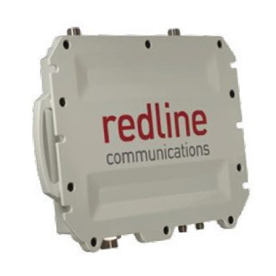
System Features System Components The RDL-3000 Ellipse wireless sector controller (subscriber) is designed and manufactured by Redline Communications, a world leader in design and production of outdoor wireless TCP/IP transport for mission critical applications. Figure 2: Features: Redline System Components... -
Page 15: Ellipse Wireless Sector Controller
The Ethernet port (RJ-45 / F connector) receives DC power and provides Ethernet connectivity with the local network. The Ethernet port connects to the PoE adapter using a weatherproof CAT-5e Ethernet cable. Figure 4: Features: Ellipse PoE Connector Pinout 70-00159-01-09 Proprietary Redline Communications © 2015 Page 15 of 52 April 29, 2015... -
Page 16: Ethernet Port Weatherproof Gland
Ellipse chassis. Use this connection to terminate a grounding wire. All Ellipse systems must be properly grounded to protect against power surges and accumulated static electricity. 70-00159-01-09 Proprietary Redline Communications © 2015 Page 16 of 52 April 29, 2015... -
Page 17: Ellipse Dimensions
INSTALLATION GUIDELINES Ellipse Dimensions The Ellipse dimensions are: 307 x 245 x 60 mm (12.1 x 9.65 x 2.3 in). Figure 6: Features: Ellipse Wireless Sector controller Dimensions 70-00159-01-09 Proprietary Redline Communications © 2015 Page 17 of 52 April 29, 2015... -
Page 18: Configuration And Management
IP address. For new systems, the default IP address is 192.168.25.2. The following login dialog should be displayed: The default username is 'admin' and the default password is 'admin'. There is no logout command on the Web interface. 70-00159-01-09 Proprietary Redline Communications © 2015 Page 18 of 52 April 29, 2015... -
Page 19: Site Survey
1 m (~3.25 ft) away from any another high frequency system antennas (e.g., microwave, GSM, CDMA, 3G) and should not be mounted within the main beamwidth of any active (radiating) antenna system. 70-00159-01-09 Proprietary Redline Communications © 2015 Page 19 of 52 April 29, 2015... -
Page 20: General Information
Path Profile The path profile should include the following information: Table 9: Site Survey: Path Profile Data Site Location Antenna Height Antenna Azimuth Antenna Elevation Expected RSSI 70-00159-01-09 Proprietary Redline Communications © 2015 Page 20 of 52 April 29, 2015... -
Page 21: Rf Interference
IMPORTANT: Refer to site survey cell plan for details about collocating multiple sector antennas on a tower/mast. Recommended antenna spacing is dependent on frequency. Figure 9: Site Survey: Ellipse Antenna Position 70-00159-01-09 Proprietary Redline Communications © 2015 Page 21 of 52 April 29, 2015... -
Page 22: Site Preparation
Ellipse sector controller is limited by the 100 m (330 ft) restriction for the total length of the Ethernet cable. Figure 10: Site Survey: System Layout Options 70-00159-01-09 Proprietary Redline Communications © 2015 Page 22 of 52 April 29, 2015... -
Page 23: Material Requirements
Important: Diagram is for informational purposes only. Installer may adjust for company standards and Industry Best Practices in effect at site location. Both AC and DC power options are available for the Ellipse system. 70-00159-01-09 Proprietary Redline Communications © 2015 Page 23 of 52 April 29, 2015... -
Page 24: Review System Grounding Requirements
Electrolytic Rods: NFPA 70-2005, Article 250.53 and NFPA 780-2004, section 4.13.2.2. Ensure all grounding complies with local electrical standards. The grounding wire may be secured using the cable hanger stack. 70-00159-01-09 Proprietary Redline Communications © 2015 Page 24 of 52 April 29, 2015... -
Page 25: Environmental Conditions (Cabinet/Shelter)
-40 to 75 °C (-40 to 167 °F) Ellipse-ER In-cabinet -40 to 75 °C (-40 to 167 °F) Surge In-cabinet -40 to 85 °C (-40 to 185 °F) Suppression 70-00159-01-09 Proprietary Redline Communications © 2015 Page 25 of 52 April 29, 2015... -
Page 26: Ellipse Lead-In Ethernet Connection
It is important to provide strain relief, drip loops and protection against vibration and abrasion caused by the wind, sand etc. The installer must provide suitable cable 70-00159-01-09 Proprietary Redline Communications © 2015 Page 26 of 52 April 29, 2015... -
Page 27: Data (Ethernet) Connection
The installer must provide suitable cable supports for the CAT-5 outdoor Ethernet cable, spaced at a recommended maximum of 450 -610 mm (~18 - 24 in). 70-00159-01-09 Proprietary Redline Communications © 2015 Page 27 of 52 April 29, 2015... -
Page 28: Power Source
The installer must provide suitable cable supports for the power cable, spaced at a recommended maximum of 450 -610 mm (~18 - 24 in). 70-00159-01-09 Proprietary Redline Communications © 2015 Page 28 of 52 April 29, 2015... -
Page 29: Installation Procedures
3. Assemble antenna mounting bracket. 4. Mount the sector controller on mast 5. Align antenna 4.4 Install In-Cabinet Equipment 1. Install PoE power injector 2. Install Ethernet surge arrestor 70-00159-01-09 Proprietary Redline Communications © 2015 Page 29 of 52 April 29, 2015... -
Page 30: Preparation
The following diagram illustrates a completed Ellipse installation. Review this diagram to become familiar with all requirements for a successful installation. Figure 17: Installation: Ellipse System Installation Example 70-00159-01-09 Proprietary Redline Communications © 2015 Page 30 of 52 April 29, 2015... -
Page 31: Step 2: Materials Supplied By Installer
Step 3: Review Site Survey Review the Site Survey section of this manual to verify that all installation requirements are complete and all installation materials are available 70-00159-01-09 Proprietary Redline Communications © 2015 Page 31 of 52 April 29, 2015... -
Page 32: Configure Sector Controller Operating Parameters
The factory default IP address is 192.168.25.2. Login to the Ellipse using the assigned username and password. The default username is 'admin', and the default password is 'admin'. 70-00159-01-09 Proprietary Redline Communications © 2015 Page 32 of 52 April 29, 2015... -
Page 33: Step 3: Restore Default Settings
Enter a valid permanent or temporary options key in the Options Key 1 field. Click Activate to enable the new features (does not require reboot). Telnet may also be used to install an options key. Refer to the RDL-3000 Family User Manual for a description of the commands. -
Page 34: Step 5: Required Network And Wireless Settings
Important: It is difficult to restore access following a lost administrator password. It is recommended to always record the administrator password and store this information in a physically secure location for future reference. 70-00159-01-09 Proprietary Redline Communications © 2015 Page 34 of 52 April 29, 2015... -
Page 35: Install Outdoor Equipment
2. Align the Ellipse as shown in the following diagram. The RF connectors should be on the same side with the V-POL and H-POL antenna leads. Figure 21: Installation - Aligning the Ellipse and Sector Antenna 70-00159-01-09 Proprietary Redline Communications © 2015 Page 35 of 52 April 29, 2015... -
Page 36: Figure 22: Installation - Mount And Secure Ellipse To Sector Antenna
4. Tighten the nuts to a torque rating of 17 N-m (12.5 ft-lb). Figure 22: Installation - Mount and Secure Ellipse to Sector Antenna 70-00159-01-09 Proprietary Redline Communications © 2015 Page 36 of 52 April 29, 2015... -
Page 37: Step 2: Connect And Weatherproof Ethernet And Antenna Cables
The Ethernet port is protected by a weatherproof gland. The Ethernet cable must be threaded through the connector components and the connector and re-assembled. The Ethernet port seal water-resistant when assembled correctly. Additional weatherproofing must be applied (see following pages). 70-00159-01-09 Proprietary Redline Communications © 2015 Page 37 of 52 April 29, 2015... -
Page 38: Figure 24: Installation: Ethernet Port Gland Assembly
Ethernet cable until it is tight against the body (2). 7. Thread the sealing nut (4) on to the body. The sealing nut must be finger-tight plus 1/2 turn. This is approximately 47 N-m (35 ft-lb). 70-00159-01-09 Proprietary Redline Communications © 2015 Page 38 of 52 April 29, 2015... -
Page 39: Weatherproof Ethernet And Antenna Ports
Seal both ends of the assembly with cable ties to prevent unravelling of the PVC tape. Do not over-tighten the cable ties, as this may compromise the weather seal. This completes the weatherproofing procedure. Figure 25: Installation: Weatherproofing Procedures 70-00159-01-09 Proprietary Redline Communications © 2015 Page 39 of 52 April 29, 2015... -
Page 40: Step 3: : Assemble Antenna Mounting Bracket
M8 Nyloc. Select the hole based on the required tilt range (0-8º or 2-10º). Hand tighten only. 70-00159-01-09 Proprietary Redline Communications © 2015 Page 40 of 52 April 29, 2015... -
Page 41: Figure 27: Installation - Integrated Sector Antenna - Tilt Brackets Detail
M8 Nut Plain Tilt Selection Bracket M8 Spring Washer M10 x 200 Setscrew M6 Nut Plain M10 Flat Washer M6 Flat Washer M10 Nut M6 Spring Washer 70-00159-01-09 Proprietary Redline Communications © 2015 Page 41 of 52 April 29, 2015... -
Page 42: Step 4: Mounting The Antenna/Sector Controller On Mast
For safety, it is recommended to use a hoisting device to raise the Ellipse to the mounting location on the tower or mast. When at the location, secure the device against 70-00159-01-09 Proprietary Redline Communications © 2015 Page 42 of 52 April 29, 2015... -
Page 43: Cable Supports
(spirit) level. This method is not accurate for elevation settings of greater than 5 degrees. To adjust the elevation, loosen the appropriate bolts of the mounting bracket. 70-00159-01-09 Proprietary Redline Communications © 2015 Page 43 of 52 April 29, 2015... -
Page 44: Install In-Cabinet Equipment
Step 1: Install PoE Power Injector Refer to the Site Survey section of this manual. 4.4.2 Step 2: Install Ethernet Surge Arrestor Refer to the Site Survey section of this manual. 70-00159-01-09 Proprietary Redline Communications © 2015 Page 44 of 52 April 29, 2015... -
Page 45: Reference
Ethernet cable at the point of cable ingress into the shelter or cabinet. Refer to the installation section for details. Figure 30: Reference: POE ETH Port Pin Assignment 70-00159-01-09 Proprietary Redline Communications © 2015 Page 45 of 52 April 29, 2015... -
Page 46: Led Indicators
PWR LED LED is on when power is detected on either V1 or V2 pairs. Power / Ground: #12 to #24 AWG Cable Gauge Chassis Ground: #10 Lug 70-00159-01-09 Proprietary Redline Communications © 2015 Page 46 of 52 April 29, 2015... -
Page 47: Ground Lug
PoE Dimensions The surge arrestor dimensions (h-d-w) are 110 x 34 x 135 mm (4.4 x 1.3 x 5.4 in). Figure 33: Reference: DC-DC PoE Mounting Dimensions 70-00159-01-09 Proprietary Redline Communications © 2015 Page 47 of 52 April 29, 2015... -
Page 48: Ac-Dc Poe
PoE OUTPUT (DATA & POWER) port. Customer premises Ethernet equipment may be damaged if connected directly to the PoE OUTPUT (DATA & POWER) port. 70-00159-01-09 Proprietary Redline Communications © 2015 Page 48 of 52 April 29, 2015... -
Page 49: Figure 35: Reference: Ac-Dc Poe Mounting Dimensions
Ellipse INSTALLATION GUIDELINES Figure 35: Reference: AC-DC PoE Mounting Dimensions 70-00159-01-09 Proprietary Redline Communications © 2015 Page 49 of 52 April 29, 2015... -
Page 50: Ethernet Surge Protection Device
Surge Arrestor Dimensions The surge arrestor dimensions (h-d-w) are: 44 x 54 x 34 mm (1.33 x 2.13 x 1.73 in). Figure 37: Reference: Ethernet Line Protection Device Dimensions 70-00159-01-09 Proprietary Redline Communications © 2015 Page 50 of 52 April 29, 2015... -
Page 51: Figure 38: Reference: Ethernet Line Protection Device - Pole Mount
Ellipse INSTALLATION GUIDELINES Figure 38: Reference: Ethernet Line Protection Device - Pole Mount Figure 39: Reference: Ethernet Line Protection Device Dimensions - Pole Mount 70-00159-01-09 Proprietary Redline Communications © 2015 Page 51 of 52 April 29, 2015... -
Page 52: Proprietary Redline Communications © 2015
Virtual Fiber™ Outdoor Wireless TCP/IP Transport 302 Town Centre Markham, Ontario Canada L3R 0E8 www.rdlcom.com 70-00159-01-09 Proprietary Redline Communications © 2015 Pahge 52 of 52 April 29, 2015...
Need help?
Do you have a question about the RDL-3000 and is the answer not in the manual?
Questions and answers