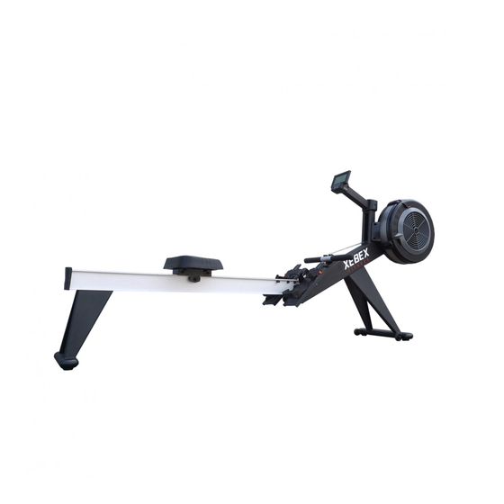
Summary of Contents for Xebex Fitness Air Rower AR-2
-
Page 2: Assembly Preparation
ASSEMBLY PREPARATION To ensure ease of product assembly, please take time to verify the size and quantities of all required assembly hard- ware. Use the itemized parts listing and hardware chart for reference. The product assembly process has been documented in easy to follow steps. Please read all assembly instructions carefully. - Page 3 (J0)M8 Nylon Nut (J1)Bolt M10x16mm (J2)Washer M10x1.5t (J3)Bolt M6x50mm (J4)Screw M4x12.7mm (J6)Bolt M8x16mm (J7)Washer M8x1.5t (J8)Pull pin (J9)Screw (J5)Bolt M8x25mm M4x10mm...
- Page 4 NOTE: Before assembly please lay out ALL pieces accordingly to ensure you are not missing any items. PLEASE BE CAUTIOUS as some components may be sharp and can cause harm if not handled correctly. Always use safety measurements when assembling any piece of equipment or machinery.
- Page 5 For best results place Forward Base (A) (Damper Fan) upside down on a soft and secure surface. Once this is done, the pre- screwed holes for Forward Base Leg (C) will be visible. To bolt in Forward Base Leg (C) into Forward Base (A), place directly on top of pre-screwed holes.
- Page 6 To finish securing Console (G) onto Forward Base (A) please attach Place Holder (H). Place Holder (H) will break up into 2 components (H1) and (H2). These components will rejoin together once attached onto forward Base (A). Once rejoined lease secure with 2 screws (J9) and 1 screw(J4).
- Page 7 To install foot pedals (E1) and (E2) into (A) Forward Base join the together by Steel Bracket (K). Steel Bracket (K) should slide into place of Foot Pedal (E1). Once placed secure with 2 (J5) bolts and 2 (J0) nuts. NOTE: You must install foot pedals before moving forward with the assembly process.
- Page 8 To install Seating place Seat Cushion (F) above the pre-screwed holes of Base Railing (B) The high angled read end of Seat Cushion (F) should face the back end of Base Railing (B). Secure with 4 Bolts (J6) and 4 washers (J7). Align Forward Base (A) with Base Railing (B) until the pre-screwed holes are aligned with one another.
- Page 9 To fold the Xebex Rower, simply pull the PULL PIN (J8) located between Forward Base (A) and Base Railing (B). This will cause Forward Base (A) to drop down and will allow you to raise Base Railing (B) so that Forward Base Leg (C) will be facing outward.
- Page 10 The Damper Lever controls how much air plows into the flywheel housing. Higher damper setting allows more resistance. Lower damper setting allows less resistance. Damper Lever Foot Height Adjuster Push down to adjust the position of the heel support.
- Page 12 M4*12mm Φ31.8 FC 2016 Iron S-type M5*10mm Cap Head Socket Screw M6*45mm Axial of Flywheel Φ20*197mm Φ100*Φ60*15T Old Design BR-6004ZZMRB Old Design Old Design Axial of Pulley(Front) Φ10*79.8mm M4*12mm A2-15 Fan stable Bracket Φ430*2.5T Main Frame Front Cap A2-16 Tapping Screw Axial of Pulley(Back) Φ10*79.8mm M4*10mm...
- Page 13 Left Pedal Rest Chain Connecting Axial Right Pedal Rest Axial of Moving Wheel Φ8X156mm Adjust Pedal Pad Left Pedal Rest Cover Aluminum Rail Right Pedal Rest Cover Seat Carriage Roller Cover M4*8mm Seat Carriage Cover Seat Carriage Wheel PR-608ZZ(BMC) Φ8*Φ12*2mm Flat Head Phillips Screw M5*15mm Seat Carriage Axial...

Need help?
Do you have a question about the Air Rower AR-2 and is the answer not in the manual?
Questions and answers