Table of Contents
Advertisement
Operation & Maintenance
The Operation and Maintenance Manual
must be read completely before operating the
engine, as it contains important safety information
and information about the operation of the engine.
The Operation and Maintenance Manual
must be included at the time of sale
Please report any service difficulties to the Technical
Support Center at Technify Motors GmbH.
See above for contact information.
Technify Motors GmbH
Platanenstraße 14
D - 09356 St. Egidien
Operation & Maintenance Manual - Issue 4 / Revision 8
Manual
CD-135
CD-155
Doc. No.: OM-02-02
Version: 4/8
CAUTION:
Note:
of the engine / aircraft.
Note:
P/N: 05-7200-H200223
Tel. +49 37204 696-0
Fax +49 37204 696-2912
www.continentaldiesel.de
support@continentaldiesel.de
Advertisement
Table of Contents

Related Manuals for Technify Motors CD-135

Summary of Contents for Technify Motors CD-135
- Page 1 The Operation and Maintenance Manual must be included at the time of sale of the engine / aircraft. Note: Please report any service difficulties to the Technical Support Center at Technify Motors GmbH. See above for contact information. P/N: 05-7200-H200223...
- Page 2 This page intentionally left blank...
-
Page 3: Table Of Contents
Operation & Maintenance Manual CD-135 / CD-155 OM-02-02 Table of Contents Chapter Description Page Table of Contents ..................3 List of Figures ...................11 List of Revisions ..................1 List of applicable Chapters .................8 Preliminary Remarks ..................9 Introduction ....................1 Accompanying applicable Document ............1 Engine Identification ...................2... - Page 4 Operation & Maintenance Manual CD-135 / CD-155 OM-02-02 Technical Data ..................1 Dimensions and Weights ................1 Performance Data ..................1 Operational Data ..................2 Operation Limits ..................2 Fuel / Oil / Coolant ..................4 Power Curve ....................8 Low Temperature Data and Climate Classes of Diesel in Europe ...10 Operation ....................1...
- Page 5 Operation & Maintenance Manual CD-135 / CD-155 OM-02-02 Airworthiness Limitations ...............1 Mandatory Maintenance Actions ..............1 5.1.1 Every 100 operating hours ............1 5.1.2 Every 300 operating hours ............2 5.1.3 Every 600 operating hours ............2 5.1.4 Every 900 operating hours ............3 5.1.5 Every 1200 operating hours ............3...
- Page 6 Every 600 operating hours ............6 6.2.6 Every 900 operating hours ............7 Every 1200 operating hours 6.2.7 (only applicable for CD-135) ............7 Every 1200 operating hours 6.2.8 (only applicable for CD-155) ............8 6.2.9 Every 1200 operating hours or every 24 months, whichever occurs first ....................9...
- Page 7 Operation & Maintenance Manual CD-135 / CD-155 OM-02-02 Annex 1 - Inspecting the V-Ribbed Belt ..............12 Annex 2 - Inspecting the Oil and Fuel System for Leakage ........13 Annex 3 - Inspecting the Cooling System for Leakage ...........14 Annex 4 - Engine Test Run ..................15 Annex 5 - Exchanging the Engine Oil and Oil Filter ..........16...
- Page 8 Operation & Maintenance Manual CD-135 / CD-155 OM-02-02 Emergency Procedures ................1 Power Loss ....................1 FADEC Operation ..................1 Engine System Malfunction ................2 7.3.1 One FADEC light flashing ..............2 7.3.2 Both FADEC lights flashing ............3 7.3.3 Abnormal engine behavior .............3 Restart after Engine Failure ...............4 Fire in the Engine Compartment ..............4...
-
Page 9: Cd-135 / Cd
Front view of CD-135 / CD-155 (dimensions in mm) Fig. 2.2 Overhead view of CD-135 / CD-155 (dimensions in mm) Fig. 2.3 Side view of CD-135 / CD-155, LH (dimensions in mm) Fig. 2.4 Side view of CD-135 / CD-155, RH (dimensions in mm) Fig. 3.5 Power curve of CD-135 (TAE 125-02-99) Fig. - Page 10 Operation & Maintenance Manual CD-135 / CD-155 OM-02-02 Fig. 6.32 FADEC read-out - Maintenance data download Fig. 6.33 FADEC read-out - Enter engine specifications Fig. 6.34 FADEC read-out - Perform engine ground run Fig. 6.35 FADEC read-out - Downloading Fig. 6.36 FADEC read-out - Choice screen Fig.
-
Page 11: List Of Revisions
Operation & Maintenance Manual CD-135 / CD-155 OM-02-02 List of Revisions Issue/ Chapter Date Approved by Revision Issue 1 / Revision 1 02-OM-00-02 27.02.2007 Hartung 02-OM-02-02 27.02.2007 Hartung 02-OM-03-02 27.02.2007 Hartung 02-OM-04-02 27.02.2007 Hartung 02-OM-05-02 27.02.2007 Hartung 02-OM-06-02 27.02.2007 Hartung... - Page 12 Operation & Maintenance Manual CD-135 / CD-155 OM-02-02 Issue/ Chapter Date Approved by Revision Issue 1 / Revision 7 02-OM-00-02 17.06.2009 Hartung 02-OM-01-02 17.06.2009 Hartung 02-OM-03-02 17.06.2009 Hartung 02-OM-04-02 17.06.2009 Hartung 02-OM-05-02 17.06.2009 Hartung 02-OM-06-02 17.06.2009 Hartung Issue 1 / Revision 8 02-OM-00-02 12.10.2009...
- Page 13 Operation & Maintenance Manual CD-135 / CD-155 OM-02-02 Issue/ Chapter Date Approved by Revision 02-OM-07-02 07.07.2010 Hartung Issue 2 / Revision 1 02-OM-00-02 12.11.2010 Hartung 02-OM-05-02 12.11.2010 Hartung 02-OM-06-02 12.11.2010 Hartung Issue 2 / Revision 2 02-OM-00-02 18.03.2011 Hartung 02-OM-04-02 18.03.2011...
- Page 14 Operation & Maintenance Manual CD-135 / CD-155 OM-02-02 Issue/ Chapter Date Approved by Revision Issue 2 / Revision 7 02-OM-00-02 19.12.2011 Hartung 02-OM-03-02 19.12.2011 Hartung 02-OM-05-02 19.12.2011 Hartung 02-OM-06-02 19.12.2011 Hartung Issue 2 / Revision 8 02-OM-00-02 04.05.2012 Hartung 02-OM-03-02 04.05.2012...
- Page 15 Operation & Maintenance Manual CD-135 / CD-155 OM-02-02 Issue/ Chapter Date Approved by Revision 02-OM-07-02 20.09.2013 Hartung Issue 3 / Revision 1 02-OM-00-02 19.12.2013 Hartung 02-OM-03-02 19.12.2013 Hartung 02-OM-05-02 19.12.2013 Hartung 02-OM-06-02 19.12.2013 Hartung Issue 3 / Revision 2 02-OM-00-02 27.01.2014...
- Page 16 Operation & Maintenance Manual CD-135 / CD-155 OM-02-02 Issue/ Chapter Date Approved by Revision 02-OM-06-02 29.08.2014 Hartung Issue 4 / Revision 2 02-OM-00-02 17.04.2015 Hartung 02-OM-04-02 17.04.2015 Hartung 02-OM-05-02 17.04.2015 Hartung 02-OM-06-02 17.04.2015 Hartung Engine Maintenance Checklist - After the 17.04.2015...
- Page 17 Operation & Maintenance Manual CD-135 / CD-155 OM-02-02 Issue/ Chapter Date Approved by Revision Issue 4 / Revision 5 02-OM-00-02 18.09.2015 Hartung 02-OM-06-02 18.09.2015 Hartung Engine Maintenance 02.09.2015 Hartung Checklist - General Issue 4 / Revision 6 02-OM-00-02 22.04.2016 Hartung 02-OM-05-02 22.04.2016...
- Page 18 Operation & Maintenance Manual CD-135 / CD-155 OM-02-02 List of applicable Chapters Document No. Document Issue Revision Date 02-OM-00-02 Lists 20.07.2016 02-OM-01-02 Introduction 30.07.2014 02-OM-02-02 Description and Dimensions of 30.07.2014 the Engine 02-OM-03-02 Technical Data 06.06.2016 02-OM-04-02 Operation 02.09.2015 02-OM-05-02 Airworthiness Limitations 06.06.2016...
-
Page 19: Preliminary Remarks
Operation & Maintenance Manual CD-135 / CD-155 OM-02-02 Preliminary Remarks The chapter numbering of the footer is different to the chapter numbering of the remaining manual. See Fig. 1.1. refers to the section of the chapter refers to the chapter Fig. - Page 20 Operation & Maintenance Manual CD-135 / CD-155 OM-02-02 This page intentionally left blank Chapter: Issue: Issue date: 30.07.2014 Page: Revision no.: Content: Revision date: 20.07.2016...
-
Page 21: Introduction
Any amendments released through the update information service must be taken into account. Please contact Technify Motors GmbH if you have any questions. We will be glad to provide further assistance. Contact address: Technify Motors GmbH... -
Page 22: Engine Identification
Operation & Maintenance Manual CD-135 / CD-155 OM-02-02 Engine Identification The serial number of the engine is provided on the data plate on the crankcase near the starter flange. Example: Data plate Fig. 1.1 Engine identification Note: When making inquiries, always have the serial number of the engine ready. -
Page 23: Copyright
Copyright © This manual, the technical data and the information contained therein are the property of Technify Motors GmbH and may not be reproduced either in full or in part or passed on to a third party without written consent from Technify Motors GmbH. -
Page 24: Packaging And Transport
Operation & Maintenance Manual CD-135 / CD-155 OM-02-02 Packaging and Transport The engine has been packaged at the factory for transport as follows: • Mounted on a support in a wooden crate • Supplied with drying agent • When the engine is transported by ship, it is packed seaworthy ... -
Page 25: Scope Of Supply
Technify Motors GmbH and integrating them into this manual. Please inform Technify Motors GmbH if the owner of the engine / aircraft changes. This is the only way to ensure that information about any necessary / recommended changes to the engine / handbook can be passed on. -
Page 26: Safety Information
• The Technify Motors GmbH engine must only be taken into operation by persons who are familiar with the corresponding manuals and who have the required level of authorization. - Page 27 Operation & Maintenance Manual CD-135 / CD-155 OM-02-02 • Only the approved equipment must be used. The use of any unapproved equipment absolves the manufacturer from any liability. • Improper installation, the use of non-suitable lines for the fuel, cooling and oil circuits, and operation with non- approved fuels or lubricants/oils absolves the manufacturer from any liability.
- Page 28 Operation & Maintenance Manual CD-135 / CD-155 OM-02-02 This page intentionally left blank Chapter: 02-OM-01-02 Issue: Issue date: 30.07.2014 Page: Revision no.: Content: Revision date:...
-
Page 29: Description And Dimensions Of The Engine
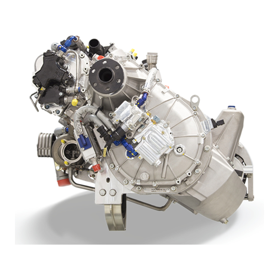
CD-155 (TAE 125-02-114) Description and Standard Production Version The Continental Diesel CD-135 / CD-155 is a liquid-cooled 4-cylinder in-line four-stroke diesel engine with DOHC (double overhead camshaft). The valves are activated by cam followers. The operation of the direct diesel-injection engine is based on the common-rail technique and is turbo charged. -
Page 30: Engine Views
The indications "right", "left", "front" and "rear" are always relative to the flight direction. The following symbol is used: Example of flight direction right: Front view CD-135 / CD-155 Fig. 2.1 Front view of CD-135 / CD-155 (dimensions in mm) Chapter: 02-OM-02-02 Issue: Issue date: 30.07.2014... -
Page 31: Issue
Fig. 2.2 Overhead view of CD-135 / CD-155 (dimensions in mm) Side view CD-135 / CD-155 (flight direction to the left) Fig. 2.3 Side view of CD-135 / CD-155, LH (dimensions in mm) Chapter: 02-OM-02-02 Issue: Issue date: 30.07.2014 Revision no.:... -
Page 32: Fig. 2.4 Side View Of Cd-135 / Cd-155, Rh (Dimensions In Mm)
Operation & Maintenance Manual CD-135 / CD-155 OM-02-02 Side view CD-135 / CD-155 (flight direction to the right) Fig. 2.4 Side view of CD-135 / CD-155, RH (dimensions in mm) Chapter: 02-OM-02-02 Issue: Issue date: 30.07.2014 Page: Revision no.: Content:... -
Page 33: Technical Data
Operation & Maintenance Manual CD-135 / CD-155 OM-02-02 Technical Data Note: All speed-related data in the operation and maintenance manual refer to propeller speeds if not otherwise explicitly specified as engine speeds. Note: The performance and operational data refer to sea level at 15°C and 0% relative humidity. -
Page 34: Operational Data
Operation & Maintenance Manual CD-135 / CD-155 OM-02-02 Operational Data Speeds: Idling speed..............890 rpm Oil pressure: Normal operating pressure.......... 2.3 - 6 bar min. 1.0 bar / max. 6.5 bar Oil temperature: Optimum operating temperature ......ca. 90 - 110°C min. 50°C / max. 140°C Coolant temperature: Optimum operating temperature ......ca. - Page 35 Max. oil pressure (cold start 20 sec.) ........6.5 bar Max. oil consumption ............0.1 l/h CAUTION: At maximum continuous power setting, the CD-135 / CD-155 is suitable for operation under negative-g conditions: of -0.2 g for 5 seconds, ...
-
Page 36: Fuel / Oil / Coolant
Operation & Maintenance Manual CD-135 / CD-155 OM-02-02 Fuel / Oil / Coolant CAUTION: Use of non-approved fuel / oil / coolant can lead to dangerous malfunctions of the engine. Fuel ............JET A-1 (ASTM D 1655) JET A (ASTM D 1655) Jet Fuel No.3 (GB6537-2006) - Page 37 Operation & Maintenance Manual CD-135 / CD-155 OM-02-02 Fuel additives JET A: ..Prist Hi-Flash Anti-Icing Fuel Additive (MIL-DTL-85470(B); ASTM D 4171) WARNING: Prist Hi-Flash Anti Icing Fuel Additive is only allowed for the operation with JET A. CAUTION:...
- Page 38 Operation & Maintenance Manual CD-135 / CD-155 OM-02-02 Coolant....Water / radiator protection in a ratio of 50:50 Radiator protection....BASF Glysantin Protect Plus / G48 Valvoline / Zerex Glysantin G48 BASF Glysantin Alu Protect / G30 Valvoline / Zerex Glysantin G30...
- Page 39 Operation & Maintenance Manual CD-135 / CD-155 OM-02-02 Note: It is recommended to use Glysantin Protect Plus Ready-Mix and Glysantin Alu Protect Ready-Mix respectively to ensure proper coolant quality. Note: The ice flocculation point of the coolant is -38°C, if mixed 50:50.
-
Page 40: Fig. 3.5 Power Curve Of Cd-135 (Tae 125-02-99)
Operation & Maintenance Manual CD-135 / CD-155 OM-02-02 Power Curve The values refer to 0% relative humidity. Altitude [ft] Fig. 3.5 Power curve of CD-135 (TAE 125-02-99) Chapter: 02-OM-03-02 Issue: Issue date: 30.07.2014 Page: Revision no.: Content: Revision date: 06.06.2016... -
Page 41: Fig. 3.6 Power Curve Of Cd-155 (Tae 125-02-114)
Operation & Maintenance Manual CD-135 / CD-155 OM-02-02 Altitude [ft] Fig. 3.6 Power curve of CD-155 (TAE 125-02-114) Chapter: 02-OM-03-02 Issue: Issue date: 30.07.2014 Revision no.: Page: Revision date: 06.06.2016 Content:... -
Page 42: Low Temperature Data And Climate Classes Of Diesel In Europe
Operation & Maintenance Manual CD-135 / CD-155 OM-02-02 Low Temperature Data and Climate Classes of Diesel in Europe Note: The officially published figures in EN 590 must be observed. Note: The minimum opening-up fuel temperature in the tank can be lowered from -5°C to -10°C if Liqui Moly „Diesel Fliess-Fit“... -
Page 43: Pre-Start Inspection
Operation & Maintenance Manual CD-135 / CD-155 OM-02-02 Operation WARNING: For operation with diesel, the aircraft must not be started if the temperature of the fuel in the tank is below -5°C (-10°C if Liqui Moly „Diesel Fliess-Fit“, No.: 5130 is added according to the manufacturer’s specifications).... -
Page 44: Start-Up
CAUTION: If external power is used for start-up of a 12V Version of the CD-135 / CD-155, ensure that a 12V supply is used. If 24V has been used, contact Technify Motors GmbH. Note: The electrical fuel pump is not included in the scope of supply of the engine;... -
Page 45: Engine Warm-Up
Operation & Maintenance Manual CD-135 / CD-155 OM-02-02 Engine Warm-up • Allow the engine to warm up for approximately 2 minutes at idle speed. • Then increase the propeller speed to 1400 rpm until the oil temperature has reached 50°C and the coolant temperature has reached 60°C. - Page 46 Operation & Maintenance Manual CD-135 / CD-155 OM-02-02 The A light extinguishes, idle speed is reached; the test is completed. Release test button. WARNING: If there are prolonged engine misfires or the engine shuts down during the test, do not attempt a takeoff with the airplane.
- Page 47 Operation & Maintenance Manual CD-135 / CD-155 OM-02-02 4.4.2 Engine test run for maintenance purposes (Real Time Log File (RTLF), Internal Data Logger (IDL), Event Log (EL)) Make sure that the Force B switch is in the automatic position. Warm-up (in accordance with Section 4.3, Page 3 of this Chapter) •...
- Page 48 Operation & Maintenance Manual CD-135 / CD-155 OM-02-02 Maintain this status for 30 seconds, then return the load selector to the idle position. • Return the Force B switch to the FADEC A position. • Using the FADEC service tool, ensure that the...
-
Page 49: Fadec-Reset (From Software 2.7 On And Following)
Operation & Maintenance Manual CD-135 / CD-155 OM-02-02 4.4.3 FADEC-Reset (from Software 2.7 on and following) In case of a FADEC-warning, one or both FADEC warning lamps are flashing. If the "FADEC" test button then is pressed for at least 2 seconds, the following possibilities will occur:... - Page 50 Operation & Maintenance Manual CD-135 / CD-155 OM-02-02 Possible reasons for activation of FADEC-Warnings are: a) Category LOW, temporary failure (one time reset is possible) - Engine_Speed ............High or Low - FADEC switchover due to FADEC A/B ....RPM difference - MAP ................
-
Page 51: Takeoff And Climb
Operation & Maintenance Manual CD-135 / CD-155 OM-02-02 b) Category HIGH, steady failure or high category failure (no reset possible by FADEC-Test Knob) - Engine Speed max. tolerated difference ECU A/B ..Exceeded - Injector ................. Error - Injector or InjectorPower........... Overcurrent - Mapping ................ -
Page 52: Cd-135 / Cd
Operation & Maintenance Manual CD-135 / CD-155 OM-02-02 This page intentionally left blank Chapter: 02-OM-04-02 Issue: Issue date: 30.07.2014 Page: Revision no.: Content: Revision date: 02.09.2015... -
Page 53: Airworthiness Limitations
Operation & Maintenance Manual CD-135 / CD-155 OM-02-02 Airworthiness Limitations AIRWORTHINESS LIMITATIONS APPROVAL SHEET (EASA) This Airworthiness Limitations Section is EASA approved and mandatory. It specifies required maintenance unless an alternative program has been EASA approved. AIRWORTHINESS LIMITATIONS APPROVAL SHEET (FAA) The Airworthiness Limitations section is FAA approved and specifies maintenance required under Sec. -
Page 54: Every 300 Operating Hours
Operation & Maintenance Manual CD-135 / CD-155 OM-02-02 5.1.2 Every 300 operating hours • Inspect gearbox (refer to Chapter 6, Annex 15, Page 63 of this Manual) • Replace clutch, if clutch assy 05-7211-K006001 or 05-7211-K006002 is installed (refer to RM-02-02, ... -
Page 55: Every 900 Operating Hours
The 1200 hrs gearbox inspection interval is only valid for P/N: 05-7212-K0435 02 CD-135 14V 05-7212-K0436 02 CD-135 28V 05-7212-K0437 02 CD-155 14V 05-7212-K0438 02 CD-155 28V 05-7212-K0439 02 CD-135 28V DA42 05-7212-K0440 02 CD-155 28V DA42 05-7212-K0413 03 CD-135 14V 05-7212-K0414 03 CD-135 28V 05-7212-K0415 03 CD-155 14V... -
Page 56: Claimable Exceeds Of Maintenance Actions
Operation & Maintenance Manual CD-135 / CD-155 OM-02-02 Claimable Exceeds of Maintenance Actions CAUTION: Exceedings must not be cumulated! 5.2.1 Maintenance Actions based on operating hours Claimable Exceeding of Operating Hours Intervals the Basic Interval up to and including 100 operating ±... -
Page 57: Examples
Operation & Maintenance Manual CD-135 / CD-155 OM-02-02 5.2.3 Examples Limited intervals based on operating hours • Maintenance action due on: 300 operating hours (100 hours check) • Maintenance action must be performed between: 290 and 310 operating hours The maintenance action is performed at the latest at 310 operating hours. -
Page 58: Log Of Revisions To Airworthiness Limitations
Operation & Maintenance Manual CD-135 / CD-155 OM-02-02 Log of Revisions to Airworthiness Limitations Issue / Revision Description of Revision Revision of the Inspection Time Intervals of the 1 / 1 Airworthiness Limitation Section Implementation of rail pressure control valve... -
Page 59: Cd-135 / Cd
Operation & Maintenance Manual CD-135 / CD-155 OM-02-02 Issue / Revision Description of Revision Increase of gearbox inspection (every 600 hrs). 3 / 0 Caution must be observed Editorial changes 3 / 1 Amendment of caution. Additional gearbox oil added. - Page 60 Operation & Maintenance Manual CD-135 / CD-155 OM-02-02 This page intentionally left blank Chapter: 02-OM-05-02 Issue: Issue date: 30.07.2014 Page: Revision no.: Content: Revision date: 06.06.2016...
-
Page 61: Maintenance Schedules
The specified maintenance schedule applies to all aircraft regardless of type and ensures the reliability of the engine. The maintenance work on Technify Motors GmbH engines must be carried out after specific time intervals or upon reaching a specific number of operating hours. It is recommended to perform a "Pre-flight inspection"... -
Page 62: Pre-Flight Check
Operation & Maintenance Manual CD-135 / CD-155 OM-02-02 "Pre-flight Check" • All switches - "OFF" • Check the engine oil level (refer to IM-02-02, Chapter 4 for filling quantities) CAUTION: When checking the engine oil level screw in the dipstick completely! ... -
Page 63: After The 3Rd - 6Th Operating Hour
Perform an engine test run according to Chapter 4, Section 4.4.2, Page 5 of this Manual, read out the FADEC. E-mail both the Real Time Log Files and Event Log Files to Technify Motors GmbH (refer to Annex 10, Page 38 of this Chapter) •... -
Page 64: Every 100 Operating Hours
Operation & Maintenance Manual CD-135 / CD-155 OM-02-02 6.2.2 Every 100 operating hours • Visual inspection of the air filter • Visual inspection of the cooling system • Visual inspection of the oil system (refer to Annex 2, Page 13 of this Chapter) •... -
Page 65: Every 200 Operating Hours
A sample of the oil and the used gearbox oil filter should be labeled, stored in a clean container and made available to Technify Motors GmbH on request for the complete engine life time. The sample will be required for later long-run analysis. -
Page 66: Every 600 Operating Hours
Operation & Maintenance Manual CD-135 / CD-155 OM-02-02 6.2.5 Every 600 operating hours • Carry out all steps described in Section 6.2.3, Page 5 of this Chapter • Carry out all steps described in Section 6.2.4, Page 5 of this Chapter •... -
Page 67: Every 900 Operating Hours
CAUTION: The 1200 hrs gearbox inspection interval is only valid for P/N: 05-7212-K0435 02 CD-135 14V 05-7212-K0436 02 CD-135 28V 05-7212-K0439 02 CD-135 28V DA42 05-7212-K0413 03 CD-135 14V 05-7212-K0414 03 CD-135 28V 05-7212-K0417 03 CD-135 28V DA42 or later approved revisions, in combination with the dual mass flywheel and the use of gearbox oil Shell Spirax S6 ATF ZM or CENTURION Gearbox Oil N1. - Page 68 Operation & Maintenance Manual CD-135 / CD-155 OM-02-02 Every 1200 operating hours 6.2.8 (only applicable for CD-155) • Carry out all steps described in Section Section 6.2.5, Page 6 of this Chapter • Replace engine shock mounts (refer to RM-02-02, ...
-
Page 69: Every 1200 Operating Hours Or Every 24 Months, Whichever Occurs First
Inspect timing chain ONLY applicable for engines Version 02 (refer to RM-02-02, Chapter 05-20.04) Every 1500 operating hours 6.2.11 (only applicable for CD-135) • Replace engine shock mounts (refer to RM-02-02, Chapter 71-20.01; 71-20.02; 71-20.03) 6.2.12 Every 1800 operating hours •... -
Page 70: Maintenance Actions Based On Time
A sample of the oil and the used gearbox oil filter should be labeled, stored in a clean container and made available to Technify Motors GmbH on request for the complete engine life time. The sample will be required for a later long-run analysis. -
Page 71: Every 24 Months
Operation & Maintenance Manual CD-135 / CD-155 OM-02-02 6.3.3 Every 24 months • Exchange coolant (refer to the aircraft manufacturer's specifications) 6.3.4 Every 60 months • Replace all fuel, oil and cooling system lines (refer to RM-02-02, Chapter 05-20.03.) ... -
Page 72: Cd-135 / Cd
Operation & Maintenance Manual CD-135 / CD-155 OM-02-02 Annex 1 Inspecting the V-Ribbed Belt This is a general visual inspection. The v-ribbed belt is to be checked for indications of wear such as abrasion and cracks. The v-ribbed belt tension is determined by spring pressure automatically. -
Page 73: Cd-135 / Cd
Operation & Maintenance Manual CD-135 / CD-155 OM-02-02 Annex 2 Inspecting the Oil and Fuel System for Leakage This is a visual inspection. Check all pipes, pipe joints, supply connections and engine housing separation points (e.g. cylinder head gasket, cylinder head cover gasket) for leakage, seepage points and correct routing. - Page 74 Operation & Maintenance Manual CD-135 / CD-155 OM-02-02 Annex 3 Inspecting the Cooling System for Leakage This is a visual inspection. The pipes, pipe joints and supply connections are inspected for leakage and seepage points. WARNING: No leakage and seepage points are permitted! No coolant loss...
- Page 75 Operation & Maintenance Manual CD-135 / CD-155 OM-02-02 Annex 4 Engine Test Run Check the starting behavior: CAUTION: Do not overheat the starter. Do not operate the starter for more than 10 seconds. After operating the starter, let it cool down for 20 seconds.
-
Page 76: Fig. 6.1 Oil Drain Plug
Note: A sample of the oil and the used oil filter must be labeled, stored in a clean container and made available to Technify Motors GmbH on request for the complete engine life time. The label must show the aircraft serial number, registration number, engine serial number, operation time and date. -
Page 77: Fig. 6.2 Oil Filter Assy
(c). See Fig. 6.2. Note: Check the oil filter cartridge for swarf and other signs of abrasion (e.g. from the bearings). Contact the Technify Motors GmbH if any are found. Replace the o-ring (a) and then insert the new oil filter cartridge (c) into the screw cap (b). - Page 78 Operation & Maintenance Manual CD-135 / CD-155 OM-02-02 Refill the engine oil. CAUTION: Only engine oil according to Chapter 3, Section 3.5, Page 4 of this Manual may be used. Note: Due to differences in the oil cooler installation the oil quantity depends upon the aircraft manufacturer.
- Page 79 Operation & Maintenance Manual CD-135 / CD-155 OM-02-02 Annex 6 Cleaning the Engine The engine must be cleaned with care. If leakage points are found, their positions must be clearly identified before they are cleaned. The engine must be cleaned only when it is cooled down.
-
Page 80: Fig. 6.3 Coolant Temperature Sensor
Operation & Maintenance Manual CD-135 / CD-155 OM-02-02 Annex 7 Checking the FADEC Sensors This is a visual inspection. Check whether the plug connections of the sensors are firmly in place. In addition, the wiring harness has to be checked for indications of abrasion. ... - Page 81 Operation & Maintenance Manual CD-135 / CD-155 OM-02-02 Fig. 6.5 Air temperarture sensor and MAP connections of the intake manifold a FADEC connection for MAP sensor b Air temperature sensor Fig. 6.6 Camshaft sensor 1 a Camshaft sensor FADEC A (1 of 2)
- Page 82 Operation & Maintenance Manual CD-135 / CD-155 OM-02-02 Fig. 6.7 Camshaft sensor 2 a Camshaft sensor 2 FADEC B (2 of 2) Fig. 6.8 Crankshaft sensor 1 a Crankshaft sensor FADEC A (1 of 2) Chapter: 02-OM-06-02 Issue: Issue date: 30.07.2014...
-
Page 83: Fig. 6.10 Gearbox Temperature Sensor
Operation & Maintenance Manual CD-135 / CD-155 OM-02-02 Fig. 6.9 Crankshaft sensor 2 a Crankshaft sensor FADEC B (2 of 2) Fig. 6.10 Gearbox temperature sensor a Gearbox temperature sensor Chapter: 02-OM-06-02 Issue: Issue date: 30.07.2014 Revision no.: Page: Revision date: 20.07.2016... -
Page 84: Fig. 6.11 Oil Pressure- And Oil Temperature Sensor
Operation & Maintenance Manual CD-135 / CD-155 OM-02-02 Fig. 6.11 Oil pressure- and oil temperature sensor a Oil pressure sensor b Oil temperature sensor Chapter: 02-OM-06-02 Issue: Issue date: 30.07.2014 Page: Revision no.: Content: Revision date: 20.07.2016... - Page 85 Note: The used gearbox oil filter must be labeled, stored in a clean container and made available to Technify Motors GmbH on request for the complete engine life time. The label must show the aircraft serial number, registration number, engine serial number, operation time and date.
- Page 86 Insert the new gearbox oil filter. For mounting direction see Fig. 6.13 and Fig. 6.14. CAUTION: Only use an original Technify Motors GmbH gearbox oil filter. Note: Make sure that the new o-ring is correctly mounted to the new oil-filter.
-
Page 87: Fig. 6.15 Lock Wiring Between Oil Drain Plug And Oil Filter Cap
Operation & Maintenance Manual CD-135 / CD-155 OM-02-02 Attach the new o-ring to the filter cap. See Fig. 6.14. Note: Make sure that the spring in the filter cap is fixed. Remount the filter cap and tighten it to the specified tightening torque. - Page 88 Note: The used gearbox oil filter must be labeled, stored in a clean container and made available to Technify Motors GmbH on request for the complete engine life time. The label must show the aircraft serial number, registration number, engine serial number, operation time and date.
- Page 89 Insert the new gearbox oil filter. For mounting direction see Fig. 6.18 and Fig. 6.19. CAUTION: Only use an original Technify Motors GmbH gearbox oil filter. Note: Make sure that the new o-ring is correctly mounted to the new oil-filter.
- Page 90 Operation & Maintenance Manual CD-135 / CD-155 OM-02-02 Fig. 6.18 Gearbox oil filter assembling a Filter element with o-ring b Sealing ring (aluminum) c Filter cap with spring Fig. 6.19 Mounting direction of the oil filter Chapter: 02-OM-06-02 Issue: Issue date: 30.07.2014...
-
Page 91: Fig. 6.20 Lock Wiring The Oil Filter Cap, The Proportional Pressure Reducing
Operation & Maintenance Manual CD-135 / CD-155 OM-02-02 Attach the new aluminum sealing ring to the filter cap. See Fig. 6.19. Note: Make sure that the spring in the filter cap is fixed. Remount the filter cap and tighten it to the specified tightening torque. - Page 92 See Fig. 6.21. Fig. 6.21 Check the oil level If the oil level is not OK, check the gearbox for leaks. If leaks were found contact Technify Motors GmbH, if no leaks were found do the following work steps. Chapter: 02-OM-06-02...
-
Page 93: Fig. 6.22 Gearbox Oil Filler Screw And Inspection Glass
Operation & Maintenance Manual CD-135 / CD-155 OM-02-02 If oil needs to be refilled loosen the oil filler screw and remove it. See Fig. 6.22. Fig. 6.22 Gearbox oil filler screw and inspection glass a Oil filler screw b Oil level inspection glass... - Page 94 Operation & Maintenance Manual CD-135 / CD-155 OM-02-02 Secure the oil filler screw with a lock wire. See Fig. 6.23. Fig. 6.23 Lock wiring the oil filler screw 10. Do an Engine Test run according to Annex 4 of this Chapter.
- Page 95 Check the oil level If the oil level is not OK, check the gearbox for leaks. If leaks were found contact Technify Motors GmbH, if no leaks were found do the following work steps. If oil needs to be refilled loosen the oil filler screw and remove it.
- Page 96 Operation & Maintenance Manual CD-135 / CD-155 OM-02-02 Fig. 6.25 Gearbox oil filler screw and inspection glass a Oil filler screw b Oil level inspection glass Fill in the new gearbox oil until the oil level reaches the top border of the oil level inspection glass (marking line in Fig.
- Page 97 Operation & Maintenance Manual CD-135 / CD-155 OM-02-02 Secure the oil filler screw with a lock wire. See Fig. 6.26. Fig. 6.26 Lock wiring the oil filler screw Do an Engine Test run according to Annex 4 of this Chapter.
- Page 98 Technify Motors GmbH FADEC system, and to facilitate organizing the data and to send this data to Technify Motors GmbH. The tool is a requirement for standard maintenance as well as troubleshooting of the powerplant. This document provides instructions for using the software.
- Page 99 4 or 5 of this annex as appropriate. The event log may be viewed without generating a file. For data to be sent to Technify Motors GmbH, the complete download appropriate to the situation should be used. Refer to section 4 and 5.
-
Page 100: Fig. 6.27 Fadec Read-Out - Start Real Time Log File
A Realtime Logfile may be generated without additional download if necessary. For routine maintenance and diagnostic support from Technify Motors GmbH the complete download appropriate to the situation should be used. Refer to section 4 and 5 of this annex. -
Page 101: Fig. 6.28 Fadec Read-Out - Enter Engine Specifications
Operation & Maintenance Manual CD-135 / CD-155 OM-02-02 Fig. 6.28 FADEC read-out - Enter engine specifications c) Enter the Engine S/N and Engine run time in the fields provided. Select OK. The window at the bottom right of the screen will indicate that the logging function is active by showing the file name in blue text. - Page 102 Operation & Maintenance Manual CD-135 / CD-155 OM-02-02 d) Conduct the engine Ground run according to the operating manual. Note: During the ground run, the user should verify that engine parameters are to spec. Compare the values of Map to MapTar, Prop RPM to PrSpdTar and PRail to PRaTar to determine any discrepancy.
-
Page 103: Fig. 6.31 Fadec Read-Out - Choice Screen
Regular Maintenance Event Note: Please send only the compressed (.zip) file generated by the tool to Technify Motors GmbH. This file will already include the eventlog and the real time log file. It is not necessary to attach these again. - Page 104 Operation & Maintenance Manual CD-135 / CD-155 OM-02-02 Fig. 6.32 FADEC read-out - Maintenance data download Fig. 6.33 FADEC read-out - Enter engine specifications b) If not already active, establish CAN communication with the FADEC by following the steps on the screen. Enter the required engine S/N and engine run time.
- Page 105 Operation & Maintenance Manual CD-135 / CD-155 OM-02-02 Fig. 6.34 FADEC read-out - Perform engine ground run c) Follow the instructions on the screen, performing the engine ground run according to Chapter 4, Section 4.4.2, Page 5 of this Manual. Press Continue. The following screen will appear: ...
- Page 106 Operation & Maintenance Manual CD-135 / CD-155 OM-02-02 Fig. 6.35 FADEC read-out - Downloading d) When the download is completed, the following screen will appear: Fig. 6.36 FADEC read-out - Choice screen e) Select the action you wish to perform: •...
- Page 107 Operation & Maintenance Manual CD-135 / CD-155 OM-02-02 • Exit to return to the main screen Note: The files generated from this download will include a real time log file, the event log, logger files and a zip file containing all of the above.
- Page 108 Operation & Maintenance Manual CD-135 / CD-155 OM-02-02 Clearing Diagnostic Warnings Should the diagnostic warning lights be active, they must be cleared after the discrepancy has been diagnosed and resolved before the aircraft can be released for service. a) Menu FADEC => Clear Warnings. The following screens will appear: Fig.
- Page 109 Operation & Maintenance Manual CD-135 / CD-155 OM-02-02 b) Enter the Password, select OK. The following screen will appear: Fig. 6.40 FADEC read-out - Enter password successfully c) Cycle ECU power and ensure that the lights on the panel have extinguished.
- Page 110 Operation & Maintenance Manual CD-135 / CD-155 OM-02-02 Annex 11 Inspecting the High-Pressure Pump The high-pressure pump must be delivered to Technify Motors GmbH for maintenance. To remove and install the high-pressure pump, refer to RM-02-02. Chapter: 02-OM-06-02...
- Page 111 Operation & Maintenance Manual CD-135 / CD-155 OM-02-02 Annex 12 Replacing the Alternator The alternator must be delivered to Technify Motors GmbH for maintenance. To remove and install the alternator, refer to RM-02-02. Chapter: 02-OM-06-02 Issue: Issue date: 30.07.2014 Revision no.:...
- Page 112 Fill 100ml of the used gearbox oil in a clean container and put a label on the container. This oil-sample must be made available to Technify Motors GmbH on request for the complete engine life time. The label must show the aircraft serial number, registration number, engine serial number, operation time and the date.
- Page 113 Oil level inspection glass c Oil filter cap d Oil drain plug Check the magnet of the oil drain plug for chips. CAUTION: In case of any chips contact Technify Motors GmbH. Chapter: 02-OM-06-02 Issue: Issue date: 30.07.2014 Revision no.:...
- Page 114 Note: The used gearbox oil filter must be labeled, stored in a clean container and made available to Technify Motors GmbH on request for the complete engine life time. The label must show the aircraft serial number, registration number, engine serial number, operation time and date.
- Page 115 Insert the new gearbox oil filter. For mounting direction see Fig. 6.45 and Fig. 6.46. CAUTION: Only use an original Technify Motors GmbH gearbox oil filter. Note: Make sure that the new o-ring is correctly mounted to the new oil-filter.
- Page 116 Operation & Maintenance Manual CD-135 / CD-155 OM-02-02 Fig. 6.45 Mounting direction of the oil filter Fig. 6.46 Gearbox oil filter assembling a Filter element with o-ring b O-ring c Filter cap with spring Attach the new o-ring to the filter cap. See Fig. 6.46.
- Page 117 Operation & Maintenance Manual CD-135 / CD-155 OM-02-02 Remount the filter cap and tighten it to the specified tightening torque. Tightening Torque: 30 Nm 10. Loosen the oil filler screw and remove it. See Fig. 6.43. 11. Fill in the new gearbox oil according to the following details: •...
-
Page 118: Fig. 6.23 Lock Wiring The Oil Filler Screw
Operation & Maintenance Manual CD-135 / CD-155 OM-02-02 15. Secure the oil filler screw with a lock wire. See Fig. 6.48. Fig. 6.48 Lock wiring the oil filler screw 16. Do an Engine Test run according Annex 4 of this Chapter. - Page 119 Fill 100 ml of the used gearbox oil in a clean container and put a label on the container. This oil-sample must be made available to Technify Motors GmbH on request for the complete engine life time. The label must show the aircraft serial number, registration number, engine serial number, operation time and the date.
- Page 120 Oil drain plug Check the magnet of the oil drain plug for chips. CAUTION: In case of any chips contact Technify Motors GmbH. Remount the oil drain plug with a new sealing ring and tighten it to the specified tightening torque.
- Page 121 Insert the new gearbox oil filter. For mounting direction see Fig. 6.51 and Fig. 6.52. CAUTION: Only use an original Technify Motors GmbH gearbox oil filter. Note: Make sure that the new o-ring is correctly mounted to the new oil-filter.
- Page 122 Operation & Maintenance Manual CD-135 / CD-155 OM-02-02 Fig. 6.52 Mounting direction of the oil filter Attach the new aluminum sealing ring to the filter cap (see Fig. 6.51, item b). Note: Make sure that the spring in the filter cap is fixed.
- Page 123 Operation & Maintenance Manual CD-135 / CD-155 OM-02-02 14. Secure the gearbox oil filter cap with a locking wire. See Fig. 6.53. Fig. 6.53 Lock wire between oil filter cap, proportional pressure reducing valve and the gearbox housing 15. Secure the oil drain plug with a lock wire. See Fig. 6.54.
-
Page 124: Fig. 6.26 Lock Wiring The Oil Filler Screw
Operation & Maintenance Manual CD-135 / CD-155 OM-02-02 16. Secure the oil filler screw with a lock wire. See Fig. 6.55. Fig. 6.55 Lock wiring the oil filler screw 17. Do an Engine Test run according to Annex 4 of this Chapter. - Page 125 Operation & Maintenance Manual CD-135 / CD-155 OM-02-02 Annex 14 Exchanging the Coolant WARNING: Risk of scalding! The cooling system may be pressurized. Carefully release the pressure before opening the drain plug. CAUTION: Do not drain the coolant if its temperature is above 40°C.
- Page 126 Operation & Maintenance Manual CD-135 / CD-155 OM-02-02 Annex 15 Inspecting the Gearbox The gearbox must be delivered to Technify Motors GmbH for inspection. To remove and install the gearbox, refer to RM-02-02. Chapter: 02-OM-06-02 Issue: Issue date: 30.07.2014 Page: Revision no.:...
- Page 127 Operation & Maintenance Manual CD-135 / CD-155 OM-02-02 Annex 16 Replacing the Excitation Battery CAUTION: Never connect a voltage to the alternator when the lines to the excitation battery are not connected. The line to the excitation battery carries a voltage from the alternator and must therefore not come into contact with a ground connection or similar.
- Page 128 Operation & Maintenance Manual CD-135 / CD-155 OM-02-02 14V-Version Disconnect the excitation battery. Remove the excitation battery holder (a). To do this, undo the four screws (c). See Fig. 6.57. Fig. 6.57 Excitation battery holder (14V) a Excitation battery holder, P/N: 20-3940-55165xx...
- Page 129 Operation & Maintenance Manual CD-135 / CD-155 OM-02-02 Annex 17 FADEC Software Update Hardware Requirements This software has been designed for Microsoft Windows 2000/XP/Vista. For proper functionality, the Microsoft .Net framework version 3.5 or newer is required (Windows Vista already contains this). If you don‘t have a proper .NET version...
- Page 130 See Fig. 6.59. CAUTION: Check all information for correctness. If there are doubts about the correctness of the information or if there are any questions about the update process, please contact Technify Motors GmbH before proceeding. Fig. 6.59 Information displayed If all information is correct, proceed to the next step by pressing "Update".
- Page 131 Operation & Maintenance Manual CD-135 / CD-155 OM-02-02 The current update status is displayed in the lower left corner. See Fig. 6.60. Fig. 6.60 Update progress After a successful update, the following message will appear. Please press "OK" to proceed to the next step....
- Page 132 Operation & Maintenance Manual CD-135 / CD-155 OM-02-02 Fig. 6.62 Previously failed update Fig. 6.63 Form One 11. Please save the Form 1. Fig. 6.64 CRC checksums Chapter: 02-OM-06-02 Issue: Issue date: 30.07.2014 Page: Revision no.: Content: Revision date: 20.07.2016...
- Page 133 CAUTION: The CRC checksums presented by the FADEC Service Tool need to match exactly with those on the Form 1(s). In case of a mismatch contact Technify Motors GmbH immediately! Fig. 6.65 FADEC Service Tool 17. Disconnect the USB CAN interface from the FADEC and your computer.
- Page 134 Operation & Maintenance Manual CD-135 / CD-155 OM-02-02 Annex 18 Inspecting the Fuel Feed Pump The fuel feed pump must be delivered to Technify Motors GmbH for inspection. To remove and install the fuel feed pump, refer to RM-02-02. Chapter: 02-OM-06-02...
-
Page 135: Emergency Procedures
Operation & Maintenance Manual CD-135 / CD-155 OM-02-02 Emergency Procedures CAUTION: If the FADEC has been operated by the battery only, a temporary decrease of the rotational speed is possible by switching on the Alternator. In any case leave the Alternator switched on. - Page 136 Operation & Maintenance Manual CD-135 / CD-155 OM-02-02 Engine System Malfunction Note: The FADEC consists of two components that are independent of each other: FADEC A and FADEC B. In case of malfunctions in the active FADEC, it automatically switches to the other.
- Page 137 Operation & Maintenance Manual CD-135 / CD-155 OM-02-02 7.3.2 Both FADEC lights flashing Note: The Load Display may not correspond to the current value. Press FADEC-Testbutton at least 2 seconds (refer to Chapter 4, Section 4.4.3, Page 7 of this Manual)
- Page 138 Operation & Maintenance Manual CD-135 / CD-155 OM-02-02 Restart after Engine Failure Whilst gliding to a suitable landing strip, try to determine the reason for the engine malfunction. If time permits and a restart of the engine is possible, proceed as follows: Air speed according to the Pilot´s Operating Handbook...
-
Page 139: Oil Pressure Too Low (During Flight)
Operation & Maintenance Manual CD-135 / CD-155 OM-02-02 Air in the Fuel System (During Flight) Move the fuel tank selector to a tank with sufficient fuel Electric fuel pump (if installed) - "ON" Engage the starter WARNING: If there is air in the fuel system, the engine stalls within a few seconds. - Page 140 Operation & Maintenance Manual CD-135 / CD-155 OM-02-02 This page intentionally left blank Chapter: 02-OM-07-02 Issue: Issue date: 30.07.2014 Page: Revision no.: Content: Revision date:...
- Page 141 To enable a smooth supply of instructions for continued airworthiness, we kindly request you to fill out this form, when you sell your engine or aircraft. Please send this form by e-mail, fax or post to Technify Motors GmbH. Name:...
- Page 142 Inspection of the timing chain FOBL E8-06 Inspection of the timing chain Technify Motors GmbH Platanenstraße 14 D-09356 St. Egidien GERMANY Dear Engine Owner, To enable a continuously improvement of our product, we kindly request you to fill out this form, when you perform an inspection of the timing chain ...
- Page 143 Operation & Maintenance Manual CD-135 / CD-155 OM-02-02 Engine Maintenance Checklist - After the 3rd - 6th operating hour General Enter the applicable data in the blocks below: Type Designation: Serial number: Engine Hours, TTSN/STSO: Manufacturer: Type: Aircraft Registration:...
- Page 144 Perform an engine test run according to Chapter 4, Section 4.4.2, Page 5 of this Manual, read out the FADEC. E-mail both the Real Time Log Files and Event Log Files to Technify Motors GmbH (refer to Chapter 6, Annex 10 of this Manual)
- Page 145 Operation & Maintenance Manual CD-135 / CD-155 OM-02-02 Engine Maintenance Checklist - General General Enter the applicable data in the blocks below: Type Designation: Serial number: Engine Hours, TTSN/STSO: Manufacturer: Type: Aircraft Registration: Operating Hours: (100, 200, 300, 400hr..., Annual Inspection)
- Page 146 Operation & Maintenance Manual CD-135 / CD-155 OM-02-02 Interval (Engine operation hours) Inspection Items Initials Visual inspection of the engine mount for chafe marks Visually inspect the air filter Visual inspection of the cooling system Check the mixture ratio of the coolant...
- Page 147 A sample of the oil and the used gearbox oil filter should be labeled, stored in a clean container and made available to Technify Motors GmbH on request for the complete engine life time. The sample will be required for later long-run analysis.
- Page 148 Operation & Maintenance Manual CD-135 / CD-155 OM-02-02 Interval (Engine operation hours) Inspection Items Initials Replace high-pressure pump (refer to Chapter 6, Annex 11 of this Manual) If TS-1 jet fuel is being used, the high-pressure pump MUST be replaced every 300 operating hours.
- Page 149 P/N: 05-7212-K0435 02 CD-135 14V 05-7212-K0436 02 CD-135 28V 05-7212-K0437 02 CD-155 14V 05-7212-K0438 02 CD-155 28V 05-7212-K0439 02 CD-135 28V DA42 05-7212-K0440 02 CD-155 28V DA42 05-7212-K0413 03 CD-135 14V 05-7212-K0414 03 CD-135 28V 05-7212-K0415 03 CD-155 14V 05-7212-K0416 03 CD-155 28V...
- Page 150 Operation & Maintenance Manual CD-135 / CD-155 OM-02-02 Interval (Engine operation hours) Inspection Items Initials FADEC maintenance (to be carried out by the engine manufacturer) FINAL INSPECTOR in block letters date, signature Engine Maintenance Checklist - General Chapter: Checklist Issue: Issue date: 17.04.2015...
- Page 151 Operation & Maintenance Manual CD-135 / CD-155 OM-02-02 this page is intentionally left blank Engine Maintenance Checklist - General Chapter: Checklist Issue: Issue date: 17.04.2015 Revision no.: Page: Revision date: 20.07.2016 Content:...
- Page 152 Operation & Maintenance Manual CD-135 / CD-155 OM-02-02 Engine Maintenance Checklist - General Chapter: Checklist Issue: Issue date: 17.04.2015 Page: Revision no.: Content: Revision date: 20.07.2016...
Need help?
Do you have a question about the CD-135 and is the answer not in the manual?
Questions and answers