Table of Contents
Advertisement
AN-49-002 Rev.: A (November 25, 2014) M149081 (R88277) File: AN-49-002(A).doc
This document and its contents are the property of Mini-Circuits
User Guide
USB/Ethernet RF Switch Matrices
USB-1SPDT-A18 / RC-1SPDT-A18
DC to 18 GHz
Single SPDT switch
USB-2SPDT-A18 / RC-2SPDT-A18
DC to 18 GHz
Two SPDT switches,
Configurable as: SPDT, DPDT or SP3T
USB-3SPDT-A18 / RC-3SPDT-A18
DC to 18 GHz
Three SPDT switches,
Configurable as: SPDT, DPDT, 3PDT, SP3T,
or SP4T
USB-4SPDT-A18 / RC-4SPDT-A18
DC to 18 GHz
Four SPDT switches,
Configurable as: SPDT, 4PDT, SP3T, SP5T,
Transfer switch and more
USB-8SPDT-A18 / RC-8SPDT-A18
DC to 18 GHz
Eight SPDT switches,
Configurable as: SPDT, SP3T, SP8T, 2x8, dual
Transfer switches and more
USB-1SP4T-A18 / RC-1SP4T-A18
DC to 18 GHz
Single SP4T switch
Advertisement
Table of Contents

Subscribe to Our Youtube Channel
Summary of Contents for Mini-Circuits USB-1SPDT-A18
-
Page 1: User Guide
Configurable as: SPDT, SP3T, SP8T, 2x8, dual Transfer switches and more USB-1SP4T-A18 / RC-1SP4T-A18 DC to 18 GHz Single SP4T switch AN-49-002 Rev.: A (November 25, 2014) M149081 (R88277) File: AN-49-002(A).doc This document and its contents are the property of Mini-Circuits... -
Page 2: Important Notice
Important Notice This guide is owned by Mini-Circuits and is protected by copyright, trademark and other intellectual property laws. The information in this guide is provided by Mini-Circuits as an accommodation to our customers and may be used only to promote and accompany the purchase of Mini-Circuits’... -
Page 3: Table Of Contents
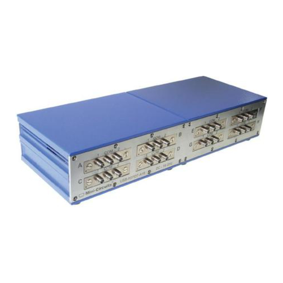
3.3.2 USB-2SPDT-A18 / RC-2SPDT-A18..............21-20 3.3.3 USB-3SPDT-A18 / RC-3SPDT-A18..............23-22 3.3.4 USB-4SPDT-A18 / RC-4SPDT-A18..............24-24 3.3.5 USB-8SPDT-A18 / RC-8SPDT-A18................26 Page 3 of 33 AN-49-001 Rev.: A (November 25, 2014) M149081 (R88277) File: AN-49-002(A).doc This document and its contents are the property of Mini-Circuits... - Page 4 3.5 Firmware update ..................31-32 3.6 Demo Mode .......................33 Figure 1: MINI-CIRCUITS USB RF SPDT Switch Page 4 of 33 AN-49-001 Rev.: A (November 25, 2014) M149081 (R88277) File: AN-49-002(A).doc This document and its contents are the property of Mini-Circuits...
-
Page 5: Chapter 1 - General Information
1.4 General safety precautions Please observe the following safety precautions at all times when using Mini-Circuits USB RF switch matrices. Ensure that all instruments using mains power supply are properly grounded to WARNING prevent risk of electrical shock. -
Page 6: Service And Calibration
For specific model features, performance data and graphs, outline drawing, ordering information and environmental specifications, see our catalog at: http://www.minicircuits.com/products/usb_rfspdt_switches.shtml Page 6 of 33 AN-49-001 Rev.: A (November 25, 2014) M149081 (R88277) File: AN-49-002(A).doc This document and its contents are the property of Mini-Circuits... -
Page 7: Intended Applications
Intended Applications 1.8.2 Mini-Circuits USB-xxxxx-A18 and RC-xxxxx-A18 series switch matrices are intended for indoor use in: - Lab and test equipment setups for both manual and automated measurements - Control systems - Automated switching of signal paths in a complex system The models can be used by anyone familiar with the basics of electronics measurements or electronic control systems. -
Page 8: Included Accessories And Options
For additional details and ordering information, click on model P/N at the top of the column. Page 8 of 33 AN-49-001 Rev.: A (November 25, 2014) M149081 (R88277) File: AN-49-002(A).doc This document and its contents are the property of Mini-Circuits... -
Page 9: Chapter 2 - Installation And Setup
If you have had any problems installing the software, we’re here to help. Try following these complete step-by-step instructions. If you still experience problems, give us a call at Mini-Circuits Worldwide Technical support. It’s (718) 934-4500 or e-mail apps@minicircuits.com for North America, or go to minicircuits.com/contact/worldwide_ tech_support.html for other regional numbers and addresses. -
Page 10: Installation
2.2.3 The installation program will launch . Click the “OK” button to continue. Figure 2.2.3 Installation Program window Page 10 of 33 AN-49-001 Rev.: A (November 25, 2014) M149081 (R88277) File: AN-49-002(A).doc This document and its contents are the property of Mini-Circuits... - Page 11 In most cases, the default will be your computer’s hard drive (C:)\Program Files\Mini-Circuits RF Switch Box\. Or Change it then click the large button at the top to continue.
-
Page 12: Usb/Ethernet Switch Matrix Physical Setup
Figure 2.3.2a: switch matrix USB control power up setup Figure 2.3.2b: switch matrix power & USB control connections Page 12 of 33 AN-49-001 Rev.: A (November 25, 2014) M149081 (R88277) File: AN-49-002(A).doc This document and its contents are the property of Mini-Circuits... - Page 13 Exceeding these values may damage the switch matrix. Hot switching with power greater than 0.1W may result in reduced switch life. Page 13 of 33 AN-49-001 Rev.: A (November 25, 2014) M149081 (R88277) File: AN-49-002(A).doc This document and its contents are the property of Mini-Circuits...
-
Page 14: Controlling The Mini-Circuits Switch Matrix
Access the switch matrix internal GUI using common web browser software (see section 3.2). Use the supplied DLL files to create your own control interface (see Mini-Circuits Programming Handbook for details). Use the supplied USB interrupt codes to create your own control interface (See Mini-Circuits Programming Handbook section 2.2 for details). -
Page 15: Chapter 3 - Using Mini-Circuits' Switch Matrix
Matrix 3.1 USB interface Mini-Circuits' GUI Switch controller USB interface allows you to test a wide variety of preset configurations while showing the current state of all switches or running timed sequences of any configuration you can imagine. The switch controller even allows you to run other programs at any point in the timed sequence you select. - Page 16 Figure 3.1.6: Ethernet Config. screen (showing factory default state) Page 16 of 33 AN-49-001 Rev.: A (November 25, 2014) M149081 (R88277) File: AN-49-002(A).doc This document and its contents are the property of Mini-Circuits...
-
Page 17: Ethernet Interface
3.2 Ethernet Interface Mini-Circuits provides two Graphical User Interfaces for Ethernet (HTTP) control of the switch matrix and one for Ethernet (Telnet). These interfaces allow you to control the switch matrix remotely from almost any computer connected to a network, or even a smartphone. If the switch matrix is connected to the same network as the computer or smartphone you wish to use to control the switch matrix you can proceed directly to control it as detailed below. - Page 18 All Programs>Mini- Circuits RF USB Switch Controller (default), or go to the other destination address you selected earlier. The “Mini-Circuits RF USB Switch Controller” icon should be waiting there for you. Click on it and get started! 3.2.4 The Switch Controller Startup screen will appear.
- Page 19 Figure 3.2.6: Ethernet startup screen Note: changing Ethernet settings is only possible via USB control, see section 3.1.7 for details. Page 19 of 33 AN-49-001 Rev.: A (November 25, 2014) M149081 (R88277) File: AN-49-002(A).doc This document and its contents are the property of Mini-Circuits...
-
Page 20: Switch Configurations
Get/Post HTTP function in your selected application (for HTTP) or establish a telnet connection(for Telnet). A full list of the commands available and their syntax is available in Mini-Circuits programming handbook chapter 2, and in a text file on the CD provided with the switch matrix, in the Ethernet directory. -
Page 21: Usb-2Spdt-A18 / Rc-2Spdt-A18
‘Back to Main’ button. Figure 3.3.2.1: USB-2SPDT-A18 SP3T configuration window Page 21 of 33 AN-49-001 Rev.: A (November 25, 2014) M149081 (R88277) File: AN-49-002(A).doc This document and its contents are the property of Mini-Circuits... - Page 22 DPDT switch. In order to return to the main window, click on the ‘Back to Main’ button. Figure 3.3.2.2: USB-2SPDT-A18 DPDT configuration window Page 22 of 33 AN-49-001 Rev.: A (November 25, 2014) M149081 (R88277) File: AN-49-002(A).doc This document and its contents are the property of Mini-Circuits...
-
Page 23: Usb-3Spdt-A18 / Rc-3Spdt-A18
‘Back to Main’ button. Figure 3.3.3.1: USB-3SPDT-A18 as a SP3T and SPDT Page 23 of 33 AN-49-001 Rev.: A (November 25, 2014) M149081 (R88277) File: AN-49-002(A).doc This document and its contents are the property of Mini-Circuits... -
Page 24: Usb-4Spdt-A18 / Rc-4Spdt-A18
‘COM->1’ to indicate the current switch state) or in the user sequence window, opened by clicking on the user sequence button (see section 3.4). Figure 3.3.4: USB-4SPDT-A18 main window Page 24 of 33 AN-49-001 Rev.: A (November 25, 2014) M149081 (R88277) File: AN-49-002(A).doc This document and its contents are the property of Mini-Circuits... - Page 25 In order to return to the main window, click on the ‘Back to Main’ button. Figure 3.3.4.2: USB-4SPDT-A18 as a SP4T and SPDT Page 25 of 33 AN-49-001 Rev.: A (November 25, 2014) M149081 (R88277) File: AN-49-002(A).doc This document and its contents are the property of Mini-Circuits...
-
Page 26: Usb-8Spdt-A18 / Rc-8Spdt-A18
(see section 3.4). Figure 3.3.5: USB-8SPDT-A18 main window Page 26 of 33 AN-49-001 Rev.: A (November 25, 2014) M149081 (R88277) File: AN-49-002(A).doc This document and its contents are the property of Mini-Circuits... -
Page 27: Usb-1Sp4T-A18 / Rc-1Sp4T-A18
For additional configurations not mentioned here of all models, or for configurations via Ethernet control click on the ‘User Sequence’ button to open the user sequence window. Page 27 of 33 AN-49-001 Rev.: A (November 25, 2014) M149081 (R88277) File: AN-49-002(A).doc This document and its contents are the property of Mini-Circuits... -
Page 28: User Sequence
Save the sequence in one of 99 sequence registers. Unless specifically named Save sequence will be saved as Seq-XX where XX is the register number. Page 28 of 33 AN-49-001 Rev.: A (November 25, 2014) M149081 (R88277) File: AN-49-002(A).doc This document and its contents are the property of Mini-Circuits... -
Page 29: User Sequence Graphical Switch Presentation
Clicking on the tab of a connector allows you to type in a new name for the connector instead of the default ‘1’, ‘COM’ or ‘2’. Page 29 of 33 AN-49-001 Rev.: A (November 25, 2014) M149081 (R88277) File: AN-49-002(A).doc This document and its contents are the property of Mini-Circuits... - Page 30 Note: Connections shown between switches need to be added by the user using external RF cables. Page 30 of 33 AN-49-001 Rev.: A (November 25, 2014) M149081 (R88277) File: AN-49-002(A).doc This document and its contents are the property of Mini-Circuits...
-
Page 31: Firmware Update
3.5.2 In order to update your switch matrix firmware, you must have a switch matrix unit with firmware revision B3 or later and a Windows computer with Mini-Circuits’ Switch Controller software installed. A power interrupt, to either the computer or the switch matrix while the firmware is being updated may cause the firmware to be corrupted. - Page 32 Click ‘OK’ to shut down the Switch Controller program and then restart it normally. Figure 3.5.7: Firmware - Successful Update Page 32 of 33 AN-49-001 Rev.: A (November 25, 2014) M149081 (R88277) File: AN-49-002(A).doc This document and its contents are the property of Mini-Circuits...
-
Page 33: Demo Mode
S/N and control method will be noted as "Demo control". Figure 3.6.2: Demo mode 8SPDT main screen Page 33 of 33 AN-49-001 Rev.: A (November 25, 2014) M149081 (R88277) File: AN-49-002(A).doc This document and its contents are the property of Mini-Circuits...
Need help?
Do you have a question about the USB-1SPDT-A18 and is the answer not in the manual?
Questions and answers