Table of Contents
Advertisement
Quick Links
Advertisement
Table of Contents

Related Manuals for Heath Company Heathkit EC-1

Summary of Contents for Heath Company Heathkit EC-1
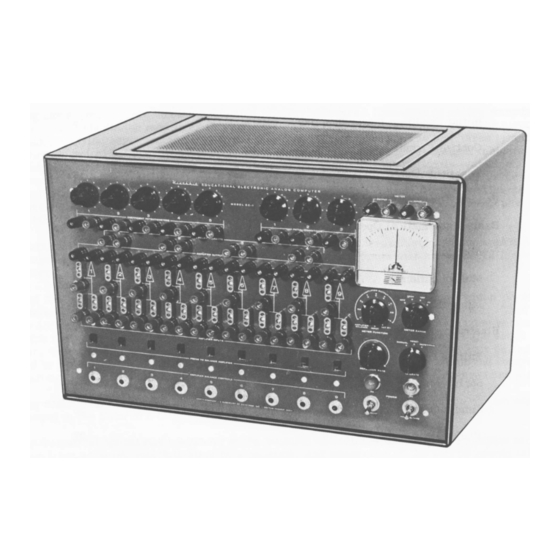
- Page 1 EDUCATIONAL ELECTRONIC ANALOG COMPUTER M O D E L EC-1...
- Page 2 STAN D ARD COLOR CODE — RESISTORS A N D CAPACITORS F IR S T R IN G S EC O N D R IN G T H IR D R IN G IN SU L A T E D U N IN S U L A TE D B O D Y COLOR E N D COLOR...
-
Page 3: Preface
OPERATIONAL MANUAL FOR THE HEATH EDUCATIONAL ANALOG COMPUTER MODEL EC-1 PREFACE The purpose of this manual is threefold: first, to present, in elementary form , the fundamental mathematical theory of analog com puters; second, to provide instructions for operation of the Heath Educational Analog Computer;... -
Page 4: Table Of Contents
CONTENTS Preface Introdufction ....................... Theory ........................Circuit Description DC Operational A m plifier ............... A m plifier Power Supply ................Initial Condition Power S u p p lie s ............. Control C i r c u i t ..................... Repetitive O s c i l l a t o r .................. General Operating I n s t r u c t io n s .............. -
Page 5: Introdufction
INTRODUCTION One of the wonders of the modern E lectronic Age is the computer or "Giant Brain", as it is som etim es called. Actually, the computer is not a "B rain” at all, since it does not think but must be "told"... -
Page 6: Theory
With the addition of special devices such as function generator and function m ultiplier, addi tional operations may be perform ed such as multiplication of variables, computation of trig onom etric, exponentional and logarithm ic functions and generation of discontinuous functions. * THEORY In order to solve differential equations on an analog computer, it is necessary to have:... - Page 7 In use, resistors and capacitors are connected as input and feedback elements in such a way as to perform various mathematical operations. For use as a multiplier, resistors are used as input and feedback elem ents, as shown in Figure 2. AMPLIFIER AS MULTIPLIER AND INVERTER In this Figure, ei represents the input voltage, eg the grid voltage, e0 the output voltage, Ri the input resistor and Rf the feedback resistor.
- Page 8 The approximation which results from considering e = 0 will be used in the further discussion of the DC am plifier but the "approxim ately equal to*' sign w ill not be used, that is, i^ w ill be considered to be eqqal to if. In practice, the gain of DC computer am plifiers w ill vary from approximately 1000 fo r repeti...
- Page 9 Suppose, for example, a ratio of 3.7 is desired. is made equal to 0.37 and R f/R f = 10 (Rf = 1 megohm and Rf = 100 Kfi), then eQ = -3.7 ej. Generally this method is to be preferred over that shown in Figure 3.
- Page 10 Since subtraction can be considered to be the addition of negative numbers, subtraction can be perform ed by using negative voltages for those quantitities to be subtracted. The circuit shown in Figure 6 would give the result o--------------------------------------------------------------------------------1 Figure 6 OPERATIONAL AMPLIFIER CIRCUIT USED FOR SUBTRACTION which may be written where...
- Page 11 where is the ratio of the voltage e0 appearing a cross the potentiometer to the voltage across the arm of the potentiometer and ground. Thus p e_ = — - — e i ° e_ = — ® Thus division by has been accom plished if R f/R f is made unity (Rf = Rf = 1 megohm, for example).
- Page 12 OPERATIONAL AMPLIFIER AS INTEGRATOR e i _ ■_ dQ Since dQ = e f d e Q this becom es Solving this equation for deQ gives the result Rj cf de0 = — ei<** Integration of both sides gives Where eiC is the constant of integration (initial condition) and is the voltage a cross the capacitor Cf at time t = o.
- Page 13 A combination of simple operations form s a com plex operation. In general, an analog computer is not used for addition alone or for multiplication by a constant as a single operation. These can be better perform ed by other means. The value of the computer lies in its ability to combine these simple operations into a com plex operation.
- Page 14 Other examples of the application of com plex operation to the solution of problem s are given in the section on OPERATION. SCALE FACTORS In the operation of the analog computer two factors must be considered. The first of these is the amplitude factor.
-
Page 15: Circuit Description
Any variations in voltages in any part of the circuit of a direct-coupled am plifier cause v a ri ations in the output voltage which in turn introduce e r r o rs in the solution. With constant input the output will vary, resulting in "d rift” , which increases with am plifier gain. This introduces a paradox since, as has been shown, e r r o r is reduced by increasing am plifier gain but this in turn increases drift which increases e r r o rs . -
Page 16: Amplifier Power Supply
The am plifier is designed around a6U8 tube with which it is possible to achieve a gain of approxi mately 1000. This is adequate for the use for which this computer is designed. This high gain is achieved by operating the pentode section of the 6U8 with a large plate load and with low volt age on the screen grid. -
Page 17: Initial Condition Power Supplies
6AQ 5A O U T P U T + 3 0 0 V O LT D.C. PO W ER S U P P L Y Figure 14 +300 VOLT DC POWER SUPPLY FOR EC-1 INITIAL CONDITION POWER SUPPLIES The voltages for the initial conditions or the "given" quantities of the problem are supplied by three initial condition power supplies. -
Page 18: General Operating Instructions
GENERAL OPERATING INSTRUCTIONS E lectrical power for the computer is controlled by two toggle switches marked FILAMENT and HIGH VOLTAGE, with green and clear pilot lamps, respectively. These switches are wired so that the filaments may be on with the high voltage off, but the high voltage will not be on unless the filament switch is in the ON position. -
Page 19: Basic Mathematical Operations
from the meter when the METER FUNCTION switch is at SET B+ or INPUT, making it unneces sary to disconnect the external read-out unit when checking the power supply voltage. Likewise, the METER INPUT term inals are disconnected atall positions of the METER FUNCTION switch except INPUT. - Page 20 As an example, consider the simple problem of finding the sum of 36 + 58. Since the sum of these numbers is greater than 60, the voltages used cannot be equal to the numbers but must be scaled down. In this case, voltages equal to 1/10 of the numbers will be suitable. The prob lem setup now looks like Figure 17.
-
Page 21: Multiplication
I MEG I MEG ■A A /V W I MEG -AAA/VH I MEG A A A A /V I MEG ' M A A A A H Figure 18 AMPLIFIERS USED FOR ADDITION AND INVERSION MULTIPLICATION Multiplication by a constant is perform ed by using different values of input resistor and feed back resistor. - Page 22 RELAY CONTACTS Figure 20 INTEGRATING AMPLIFIER WITH RELAY CONTACTS When the OPERATION switch is in the RESET position, the relay contacts are all closed. Connect the two binding posts on either end of the feedback socket to the two relay contacts 1, as shown in Figure 21.
-
Page 23: Illustrative Problems
Figure 22 A Figure 2 2 B (a) A s observed on oscilloscop e. (b) A s recorded by pen record er. OUTPUT VOLTAGE eQ VS. TIME t FOR AMPLIFIER USED AS INTEGRATOR The operations just carried out illustrate the basic operations perform ed by the com puter, but the real value of the computer lies in combining these elementary operations in such a way as to solve problem s. - Page 24 0 o = + y — o °—VWW Figure 23 FALLING BODY PROBLEM CIRCUIT The value of g is supplied by one of the IC power supplies. Some way must be provided for d is charging the capacitors at the end of the solution of the problem . This can be accom plished by connecting the capacitor to the relay contacts which are open during solution of the problem and closed during the "...
- Page 25 moves too rapdily, turn the control counterclockw ise. Turn the OPERATION switch to RE PETITIVE. The computer w ill now reset itself and repeat the solution at a rate controlled by the REPETITION RATE control knob. This w ill continue until the OPERATION switch is returned to the RESET position.
-
Page 26: Spring-Mass System
The previous problem considered the body to be falling without friction. If there exists a frictional fo rce, proportional to the velocity the equation of motion becom es d 2 y „ d Y m - d R + c d T + 9 = 0 d 2 y _ d t 2... - Page 27 The differential equation of the spring-m ass system shown in Figure 29 is M ^ + s d f + K y = F l , ) y (o) = (o) = o . with The last expression states that the displacement at time equals zero (the start of the problem solution) y (o) and the velocity at time equals zero (o) are both zero.
-
Page 28: Simultaneous Algebraic Equations
SIMULTANEOUS ALGEBRAIC EQUATIONS A different type of problem is one involving simultaneous algebraic equations. A system of two equations in two unknowns may be represented by the equations a, x + b,y = C, ajX + —C These equations may be rewritten in the form 2L_ | y a 2 b2 The computer circuit for these equations is shown in Figure 32. -
Page 29: P R O Je C T I L E
The computer circuit for these equations is shown in Figure 33. im eg CIRCUIT FOR SIMULTANEOUS EQUATIONS The values of x and y are read on the meter. Control A is set so that the voltage drop between the center lugs and ground is 1/3 the voltage drop a cross the control. -
Page 30: Bouncing Ball
The basic computer setup is shown in Figure 34. of T= 0 Figure 34 COMPUTER SETUP FOR PROJECTILE PROBLEM The components of the initial velocity are controlled by IC-1 and IC-2, while the acceleration to gravity, g, is controlled by IC-3. Air resistance is controlled by the controls m /c. - Page 31 20 K£2 (0.02 megohm) resistor 200 K£2 (0.2 megohm) resistor 500 Kfi (0.5 megohm) resistor 2 megohm resistor 5 megohm resistor 10 megohm resistors The resistors should preferably be 1% tolerance, but 5% or even 10% resistors w ill be satis factory for demonstration purposes.
- Page 32 — |i‘ a a m g «—V W \A r-|l‘ A M M /— -AMA/V..□ > o ro L- < D Z I < O DC < V | - Figure 38 Page 30...
-
Page 33: R E Fe R E N C E S
REFERENCE BOOKS ANALOG COMPUTERS Goode, Harry H. and Machol, Robert E . , SYSTEM ENGINEERING, M cGraw-Hill, 1957. Johnson, Clarence L . , ANALOG COMPUTER TECHNIQUES, M cGraw-Hill, 1956. Karplus, Walter J. , ANALOG SIMULATION, M cGraw-Hill, New York, 1958. Korn, Granino A. -
Page 34: Specifications
Reque, S. G ., "Simulate the System With an Analog Computer", Control Engineering, September, 1956, Pages 138-144. Heald, Carl, "Putting the Analog Computer to W ork", ISA Journal, Vol. 3, No. 8, August 1956, Page 270. Howe, R. M ., and Haneman, V. S ., "Solution of Partial Differential Equations by Difference Methods Using the Electronic Differential Analyzer", Proceedings IRE, Vol. - Page 35 RELAYS A relay with four sets of contacts provides for applying initial condition voltages and for r e setting problem s. REPETITIVE OPERATION A multivibrator provides for automatic operation at from approximately 0.1 to 15 cps. MAIN POWER SUPPLY The positive supply is electronically regulated and provides +300 volts at 25 ma.
- Page 36 GRAPHS The following graphs show the response of atypical DC am plifier of the EC-1. Individual am pli fie rs w ill show some variation from these curves. LO A D RESISTANCE IN OHMS. FREQUENCY IN CYCLES PER SECOND Page 34...
- Page 37 FREQUENCY IN CYCLES PE R SECOND Page 35...
-
Page 38: Parts L I S T
To aid in the identification of parts, drawings of some of the parts are shown opposite the part description. CONSTRUCTION COMPONENT PARTS LIST DESCRIPTION PARTS PART Per Kit 1/2 Watt R esistor Composition R esistors E ra s'ji: ar 84-12 1-10 12000 1/2 watt 1-69... - Page 39 PART PARTS DESCRIPTION 2-lug Termina Per Kit Crystal Socket Strip Sockets-Term inal Strips-Knobs 434-15 7-pin miniature wafer socket 9-pin miniature wafer socket 434-16 434-38 Crystal socket Dual silicon diode holder 422-2 434-22 Pilot lamp assem bly, green 434-69 Pilot lamp assem bly, clear 1-lug terminal strip 431-1 431-2...
- Page 40 PART PARTS DESCRIPTION Per Kit W ire-C able-S Length 4 - conductor cable 347-7 347-1 Length 8 - conductor cable 8-conductor laced cable assem bly 134-2 9-conductor laced cable assem bly 134-3 Line cord 89-1 Length insulating sleeving 346-1 Length 3 /1 6 " clear plastic sleeving 346-2 Length #5 clear plastic sleeving (largest) 346-7...
- Page 41 PROBLEM SOLVING COMPONENTS PART LIST PARTS DESCRIPTION PART SILICON P er Kit _______________ DIODE 100 KS2 precision resistor 2-11 1 meg 1% p recision resisto r 2-14 0.1 jufd 200 volt 5% m ylar capacitor 27-1 1.0 jufd 200 volt 5% m ylar capacitor 27-2 Silicon diode 56-5...
- Page 42 i = 5 j u...
- Page 43 HELPFUL KIT BUILDING INFORMATION Before attempting actual kit construction read the construction W IR IN G manual through thoroughly to familiarize yourself with the general When following wiring procedure make the leads as short and direct procedure. Note the relative location o f pictorials and pictorial inserts as possible.
- Page 44 HEATH COMPANY A S u b s i d i a r y o f D a y s t r o m I n c . F O R M T H E W O R L D ' S...
Need help?
Do you have a question about the Heathkit EC-1 and is the answer not in the manual?
Questions and answers