Table of Contents
Advertisement
Advertisement
Table of Contents

Summary of Contents for assemblage SET-300B
- Page 1 Construction and Operation Manual...
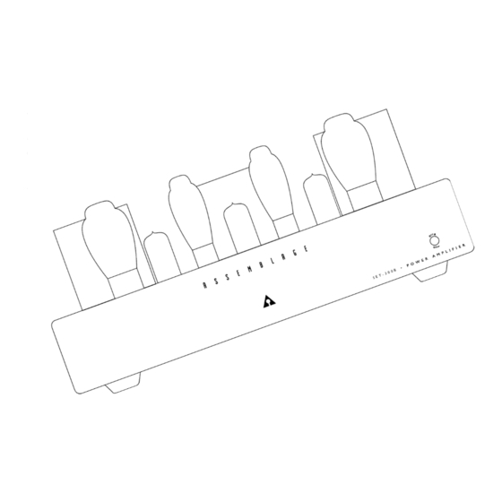
- Page 2 Congratulations on purchasing the Assemblage SET-300B power amplifier. We are very proud of the Assemblage SET-300B, both technically and perhaps more import a n t l y, sonically. Utilizing modern, high quality parts, the SET-300B has been designed to pro v i d e many years of tro u b l e - f ree operation, using readily available tube types (these are tube types, which are still in production - and will continue to be so).
-
Page 3: Parts List
Parts List Signature Please note, if you are planning to install the Parts Upgrade kit at this same time, take note of the parts labeled “Sig.” in this manual. Refer to the Parts Upgrade Instructions for these replacement parts. I t e m / Va l u e Q t y / U n i t R e f e rence Designators I t e m / Va l u e Q t y / U n i t R e f e rence Designators... -
Page 4: Tools Required
Tools Required In addition to the parts supplied in the kit, you will need the following tools to complete construction of the SET-300B kit. Pencil tip soldering iron of good quality (700°F tip temperature) #0 Philips screwdriver 12mm wrench or ratchet (1/2” will also work) 10mm combination wrench (not shown) (3/8”... - Page 5 SET-300B Functions...
-
Page 6: Control Functions
Control Functions A LED When the coool blue LEDis lit, the SET-300B is “ON”, receiving power from the power supply. B ON-OFF button When in the ON position (button depressed), high voltage power is received by the SET-300B circuitry f rom the power source. Due to the warm up characteristics of tubes, it will take 30 seconds for the tubes to pass full signal. - Page 7 N O T E : Talking about part substitutions, there are Signature part s minutes to read this preface on the construction manual and the kit. upgrade kits available for the SET-300B. These upgrade kits re p l a c e components in the signal path, input wiring, power supply filter caps,...
- Page 8 Wire Stripping with a Knife If you own a wire stripper, we’re assuming you know how to use careful to cut only the insulator and not the wire itself. Pull the it. If not, and you are new to the world of audio construction, you excess insulation away and you have your lead.
- Page 9 Assembled PC Boards...
- Page 10 Main PC Board Parts Placement Guide...
-
Page 11: Assembly Instructions
Assembly Instructions Next these are all - raised above PCB 3/16” (4mm)! R4, LR4 33K 2W* (Sig) R209A, B, LR209A, B 68K 2W* On Left & Right CH Filter Banks PC Board Preparations: R300 100K 2W* I know that you are more than ready to go, so lets start off by pre p a r i n g R210, LR210 150K 2W* On Left &... - Page 12 C1, LC1 470uF 16V (Sig) This is very important to do because the heat being applied while C2, LC2 220uF 160V soldering on the extensions can easily destroy the LED! We need to C4, LC4 100uF 100V (Sig) keep this ‘coool blue’ LED cool! C5,6, LC5,6, 10uF 450V C300...
- Page 15 RCA jack. assembly pro c e d u res involved with this SET-300B construction kit. One more finer detail, bend the solder lug out to 45 degrees fro m 300B Tube Sockets: the chassis.
- Page 16 F rom the rear side of the chassis screw on the switch nut using a Shielded 4 Conductor Input x 24” (710mm) (Sig) 5/16” nut-driver, lightly tighten it. Installation of the lock washer is Signal cable optional. These switches can be delicate, be careful not to over 3/16”...
-
Page 17: Main Chassis Assembly
M3 10mm (3/8”) Blk CS screws Relocate the choke mounting hard w a re that you put aside (#8 nuts Solder lug and screws), and relocate the two mounting holes in the center rear of 6-32 1/4” Zinc Philips screw the chassis. - Page 18 O/P for a diff e rent speaker load. of you who would prefer to run your SET-300B as a mono block, this CUE: If you approach the post from the center of the chassis, the wire next setup is for you.
- Page 19 Now to configure the secondary windings for the desired speaker describes the setup for your particular AC line voltage. (We’ll see if you load, please first refer to the following chart . did something wrong later and decide your consequences then!) 3/16”...
- Page 20 200V operation: You have rolled the dice, please advance down to ‘STICKY Pad P l a c e m e n t ’ . Snuggly twist the BLACK and BROWN wires together. Snuggly twist the WHITE and BRN/ORG wires together. 240V operation: P re p a re and trim the BLK/WHT wire to 9”...
- Page 21 STICKY Pad Placement: P re p a re all of these wire sets for soldering, we will need them soon. Now that you made it here safely I hope, go back one step to AC SW PCB Mounting. Main Filter Bank Connections: S t a rting here we will be interconnecting all the remaining PCB’...
- Page 22 Connect the RED wires to the pads labeled LB+1 and B+1 on the flanking L & R Filter Bank PC boards. Repeat the process to connect Mounting the PCB’s into the Chassis: the Black wires to the LCOM and RCOM from the common c l u s t e r Yes we are getting very close now to filling the chassis and fulfilling pads ‘L’...
- Page 23 Now we are done the soldering and now we are done the constru c t i o n socket closest to you. of your new Assemblage SET-300B Amplifier! How does it feel? Or better yet, how does it look? “Looks great! But, how does it sound?”...
-
Page 24: Trouble Shooting
TPC and I believe that you will enjoy your new Assemblage SET-300B Amplifier for many years to come. Please feel f ree to call or write us to let us know any of your comments on this p roject, good or bad. -
Page 25: Technical Specifications
Technical Specifications Note: Specification ratings based on the nominal power line input for the country in which it is used Power Output: Stereo 8 watts per channel continuous both channels driven, into 4, 8 or 16 Ohms (user selectable), Mono 16 watts continuous into 8 or 16 Ohms (user selectable) Frequency Response (8 watt, 4 ohm) - Page 26 Assemblage SET-300B Signature Upgrade Kit Preview: At this time I would like to re f resh your memory to the fact that as with all of our other Assemblage kits, this SET-300B amplifier also has an additional special selection of upgrade parts available.
- Page 27 Toll Free Help Line If you have any questions regarding the assembly or installation of the Assemblage SET-300B kit, please give us a call at The Parts Connection at: Toll Free: 1-800-769-0747 (U.S.and Canada) Telephone: (905) 829-5858 Facsimile: (905) 829-5388...
Need help?
Do you have a question about the SET-300B and is the answer not in the manual?
Questions and answers