Advertisement
Quick Links
【Operation Manual】
Series
Output
name
SP-556
No
code
GL
P2
AV3
AV4
AV5
AI
*1 "B" Option and "BI" Option cannot be selected together.
*2 Optional "DC" is outside CE marking.
*3 The meter is an subject of CE Marking. But box-type (DM) is off the subject of CE Marking.
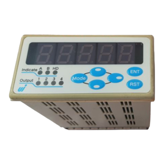
Digital speed meter
MODEL: SP-556 Se rie s
Sensor
Input
Power
B *1
BI *1
No
code
F
V3
N
L1
F2
F2W
HI
No
code
S24
Power type Color Cover
No
code
DC *2
DM *3
No
code
K
No
code
C
Function
Preset output two point
(NPN open collector output)
7segment red LED
7segment green LED
Two point Photo MOS relay output
Analog voltage output (DC 1-5V)
Analog voltage output (DC 0-5V)
Analog voltage output (DC 0-10V)
Analog current output (DC 4-20mA)
BCD output
BCD input
NPN Open Collector pulse input
Voltage pulse input
Tacho-generator signal input AC 0.8V-80V(P-P)
Si n e wave si g nal i n put AC 0.05V-20V(P-P)
Line receiver 1CH (A・A) input
Current modulation pulse input(A-input)
Current modulati o n pulse input(A-i n put, B-i n put)
High-speed input (0.01Hz~120kHz)
DC12V 100mA
DC24V 60mA
Power source:AC 100V-240V
Power source:DC 12V-24V
Unredeemable type
Gray
Black
not attached
Terminal stand cover
【 8th
8 Sep. 2015 】
@SP-556CE(8)-E
Advertisement

Subscribe to Our Youtube Channel
Summary of Contents for UI SP-556 series
- Page 1 【Operation Manual】 Digital speed meter MODEL: SP-556 Se rie s Series Sensor Output Input Power type Color Cover Function name Power Preset output two point SP-556 (NPN open collector output) 7segment red LED code 7segment green LED Two point Photo MOS relay output Analog voltage output (DC 1-5V) Analog voltage output (DC 0-5V) Analog voltage output (DC 0-10V)
-
Page 2: Product Description
Precautions Please read this Operation Manual including the following precautions carefully to ensure safe use of your meter. ! <Caution> Do not use this product for applications outside of the product specifications. ! <Caution> User-conducted alterations and modifications of the unit should not be performed as they may impair functioning or cause failure and accidents. - Page 3 Contents 1.About confirmation of an attachment. and a guaranteed period ・・・・・1 2.Specifications ・・・・・・・・・・・・・・・・・・・・・・・・・・・・・・・・2-4 3.Mounting meter ・・・・・・・・・・・・・・・・・・・・・・・・・・・・・・5 4.Names and functions of components on front ・・・・・・・・・・・・・・6-7 5.Connecting terminal boards ・・・・・・・・・・・・・・・・・・・・・・・・8-9 6.Construction of input circuit ・・・・・・・・・・・・・・・・・・・・・・・・10 7.D ip switch ・・・・・・・・・・・・・・・・・・・・・・・・・・・・・・・・・11 8.The setting menu ・・・・・・・・・・・・・・・・・・・・・・・・・・・・・12-13 9.Initial setting values and initialization ・・・・・・・・・・・・・・・・・・・・14...
- Page 4 1.About confirmation of an attachment and a guaranteed period About confirmation of an attachment. When you received as a product, please confirm whether it includes the following. (1)SP-556(The chosen specification) ・・・・・・・・・・・・・・・1 (2)SP-556 Operation manual (This book) ・・・・・・・・・・・・・1 (3)Unit label(Attachment) ・・・・・・・・・・・・・・・・・・・・・・・1 If there are the mistaking parts and the missing parts, please inform a dealer or us.
-
Page 5: Specifications
2.Specifications (1) Standard specifications Item Specifications Ratemeter (speed, rotation,flow rate,), differential rate, Measuring types ratio, shot speed, passing time, cycletimer, stop watch Measuring system Periodic sampling operation Scaling (Pulse rate) 1×10 – 9999 (selectable) < speed, rotation, flow rate, differential rate, ratio, passing time > ±0.05% rdg.±1digit ( at Sampling time for 0.5 second or more , per one input ) Measurement... - Page 6 Mode protect Protection of the mode setting Each mode setting value is memorized by FRAM(The memory number Data backup of times is within 100,000 times, About 10 year safekeeping.) AC 100-240V (-15% / +10%) 120mA max Power supply 50/60Hz approx 20VA Power supply (DC) DC 12-24V ±10% Operating temperature...
- Page 7 《Analog output:AV3-AV5 / AI option》 Output terminal Output terminals No.19-20 (Analog output) Voltage output (AV) 0-5V, 1-5V, 0-10V load impedance 2kΩ or more Current output (AI) DC 4 - 20mA load impedance 500Ω or less Output accuracy Within ±0.3%F.S. for indicated value (at 23℃) The temperature ±100 ppm/℃...
- Page 8 3.Mounting meter How to mount meter 1. Cut the panel to insert the meter from the front. Panel cutout dimensions +0.8 Meter Installation board Packing Fig.1 Unit (mm) 2. Please push the Fitting for fixing the body. Into a right and left both sides of the meter. Fitting for fixing the body Fig.2 Slide in the rear side (terminal stand side)
- Page 9 4.Names and functions of components on front Display Fig.4 Indicat e E N T M ode O ut put R ST ①Display unit ( A to E ) Measurement state:Measurements are displayed. Setting state:When the mode is set, it displays it as follows. A・・・・・Mode No.
- Page 10 ⑨ Mode key Mode Measurement state:It enters the mode setting state if + are pushed Mode for 2 sec. or more. :It enters the preset output setting state if only is pushed Mode for 2 sec.or more. Setting state:When the mode is set, the mode number is raised. When the preset output is set, OUT1-4 is changed.
- Page 11 5.Connecting terminal boards Fig.5 Tacho-generator Sine wave Other power source Option:V3, N Line driver Option:L1 Pulse sensor B Pulse sensor A Preset output N.C. GND A.IN B.IN BCD output (option) F.G. N.C. AC100-240V AV / AI DC12-24V ! <Caution> 1)For safety, professional wiring electrical work, such as electrical wiring is please go. Please shut off the power when electrical wiring.
- Page 12 A. Tacho-generator / Sine wave B. Pulse output 2-wire type sensor Fig.6 Fig.7 Sensor-A Tacho-generator (V) Sine wave(N3) Sensor-B 7 8 9 8 C. Ground contact output sensor D. Line driver encoder Fig.8 Fig.9 Line driver A input B input 8...
- Page 13 6.Construction of input circuit ① NPN open collector pulse input Fig.13 +12V +12V 2.2K Sensor power SW5,6 1.5K 100K ② Voltage pulse input ③ Reset・Hold input Fig.14 Fig.15 +12V +12V +12V 2.2K 4 , 2 SW5,6 1.5K 2.2K 又は 6 , 3 100K ④...
- Page 14 7.Dip switch Sensor input, and relationship of the sensor input response is shown in Table1. Table.1 B.IN A.IN B.IN A.IN OFF⇔ ON Input frequency 0.01Hz - 50Hz LOW OFF OFF Input frequency 0.01Hz - 1kHz MID Input frequency 0.01Hz - 10kHz HI OFF OFF OFF Input frequency 0.01Hz - 120kHz ※...
- Page 15 8.The setting menu ≪Test Mode≫ Power supply OFF Turn power supply on with being pressed. M ode Test mode M ode M ode M ode E N T M ode R ST M ode M ode E N T M ode E N T M ode R ST...
- Page 16 ≪Setting menu≫ Power supply OFF Turn power supply on. E N T E NT E NT Measurement E NT E N T <Teaching> Press for 2 sec. or more. M ode E N T R ST <The preset value setting> Press for 2 sec.
- Page 17 9.Initial setting values and initialization If the specifications desired by the user are requested prior to shipment, the meter will be set these settings. Other wise, the regular factory settings are shown below. Value setting of each mode (Table 2) Mode No.
- Page 18 10.Content and setting the each mode ≪1.Operating method (the mode setting)≫ When doing mode setting, please operate as follows. Table.4 Operating key Indication Procedure While pushing down , press M ode A B C D E for 2 sec. or more. 0.0...
- Page 19 ≪2.Content of the each mode and set value≫ Mode No. Measuring types, Measurement unit, Display decimal point A B C D E 0 0.0 0 2 1 Display decimal point setting 0: 2: 0.00 1: 3:0.000 Measuring unit 0:hour 1:minute 2:second 3:hour-minute The above measurement selecting...
- Page 20 〔Ratio measurement〕 absolute ratio measurement ・・B/A×100 (02) error ratio measurement ・・・・(B-A)/A×100 (03) difference measurement ・・・・A-B (04) density・・・・・・・・・・・・・B/(A+B)×100 (05) sum measurement ・・・・・・・A+B (06) 〔differential rate measurement〕 There is a signal of two kinds of number of revolutions of A and B, The 2 signals are input, and the following calculation is considered to be it.
- Page 21 (08) 〔Passing time measurement〕 When it is measured time via P2 by P1(Distance, Oven-length, tact pitch), please choose this mode. Set the unit of scaling in ”mm”. (Refer to Mode No. 5:Oven-length (tact pitch) setting) Oven-length (tact pitch)(Ex.:3.00m) 〔Shot speed〕 (09)...
- Page 22 (13) 〔Cycle-timer measurement〕 1)When sensor input A does ON, it is started time measurement. 2)It is displayed measurement time when sensor input did ON again, and time measurement is started again. 3)The time measurement is suspended between ON sensor input B. 4)When ON did reset input, indication is returned to 0, and the time measurement stops.
- Page 23 (15) 〔Stop watch B〕 1)When sensor input A does ON, a measurement is started and displays it at the same time. 2)When ON does B sensor next, a measurement stops. 3)When reset input is performed ON of, indication and the internal counter are corrected to 0 and are stopped time measurement Indication Indication...
- Page 24 Mode No. A-input:Setting of scaling data A B C D E 1 1.1 0 0 0 Scaling data:0001 – 9999 (Do not set 0000) Please set the pulse rate (scaling data) of the sensor. 4 digit of numerical value to set with this mode, and please input Exp.value of -9...
- Page 25 Calculation example of scaling data (setting example) Example Arithmetic expression In case of " Revolution " Scaling data=1revolution/pulse Arithmetic In case of " Speed " expression Scaling data=Amount of transfer/pulse In case of " Flow " Scaling data=Flow rate value/pulse Factor →1...
- Page 26 Mode No. A-input:Exp.value, moving average, auto-zero time A B C D E 2 2.3 0 0 2 Auto-zero time 0:Disable 5:10 sec. 1:0.5 sec. 6:20 sec. 2:1 sec. 7:30 sec. 3:2 sec. 8:60 sec. 4:5 sec. 9:120 sec. Moving average 00-19 times(00 and 01 are equivalent in effect.)...
- Page 27 〔Ex.〕The magnification per 1 signal assumes it 0.1234, and the moving average zeroes indication by invalidity five seconds after the last input signal. A B C D E Mode No.1 -4 1.1 2 3 4 B~E: (1234×10 =0.1234) A B C D E Mode No.2 2.4...
- Page 28 Mode No. Deceleration ratio/Oven-length (tact pitch) setting 〔Deceleration ratio setting〕 ※This mode is effective in Mode No.0 Measuring types 5 「07:differential rate measurement」setting A B C D E 5.1 0 0.0 Deceleration ratio R:000.1 - 999.9 ( Do not set 000.0 ) 〔Oven-length (tact pitch) setting〕...
- Page 29 Mode No. Sampling time A B C D E 6 6. 0 2.0 Sampling time:00.0 - 99.9 seconds (00.0 shall be the real-time display.) For sampling time, input signal is measured with its set time, and its mean value is calculated and displayed, then, use it for preventing the flashing or for stabilizing the display.
- Page 30 Mode No. Hold input function setting, display blank, lowest digit display A B C D E 7 7.0 0 0 Lowest digit display 0:Real 1:Fixed at 0 2:0 or 5 Display blank 0:Normal display 1:Blank display Hold input function setting 0:No use 1:Peak hold 2:Bottom hold...
- Page 31 Mode No. OUT1:Preset output (open collector output) A B C D E 8 8.0 0 0 0 Output mode 0:Comparison 5:100 ms (1 shot) 1:Hold 6:250 ms (1 shot) 2:10 ms (1 shot) 7:500 ms (1 shot) 3:20 ms (1 shot) 8:1 sec (1 shot) 4:50 ms (1 shot) 9:2 sec (1 shot)
- Page 32 Mode No. OUT2:Preset output (open collector output) A B C D E 9 9.0 0 0 0 Output mode 0:Comparison 5:100 ms (1 shot) 1:Hold 6:250 ms (1 shot) 2:10 ms (1 shot) 7:500 ms (1 shot) 3:20 ms (1 shot) 8:1 sec (1 shot) 4:50 ms (1 shot) 9:2 sec (1 shot)
- Page 33 Mode No. OUT4:Preset output (photo MOS relay output) (Option P2) A B C D E b b.0 0 0 0 Output mode 0:Comparison 5:100 ms (1 shot) 1:Hold 6:250 ms (1 shot) 2:10 ms (1 shot) 7:500 ms (1 shot) 3:20 ms (1 shot) 8:1 sec (1 shot) 4:50 ms (1 shot)
- Page 34 Mode No. Analog output:Setting of measurement choice and the output digit (Option AV3-5/AI) A B C D E C C. 1 0 Digit selection 0:Right 4digits:comparison 1:Left 4digits:comparison Analog output method 0:Real time output 1:Synchronizes for display 2:Synchronizes for measurement (calculation value) 〔Digit selection〕...
- Page 35 Mode No. Analog output:Setting of maximum output indication (Option AV3-5/AI) A B C D E d.1 0 0 0 d Indication value:0001 - 9999. (Do not set 0000) Set an indication value of the time when the analog output is maximum. Set a value in four digits, neglecting the decimal point.
- Page 36 Mode No. BCD input setting (Option BI) A B C D E F F.0 0 1 BCD input (logic selection) 0:High active (Each pin and GND is open) 1:Low active (Each pin and GND is Short) Latch input (logic selection) 0:”Short”...
- Page 37 11.Mode protect function When the mode protect function is made effective, operation is invalid by mode setting. Therefore the set value can't be changed. In an early stage,the mode protect function is invalid . When doing the mode protect function setting, please operate as follows. ≪Operation of the mode protect≫...
- Page 38 12.Teaching function What is the teaching function? Change the current indication level to any value. (setting automatic as for the scaling data.) [Ex.] when input frequency 100Hz is displayed as 200.0rpm, for changing the display value from 200.0 to 180.0, converted value may be changed, whereas, upon setting ”180.0”by the teaching function, 180.0 is automatically displayed.
- Page 39 13.Calling up and modifying the preset value setting Set the value to pre-set of the preset out by the following method. The set range is “-9999” - “99999” In addition, please refer to Mode No.8-b (P.28-30) for the setting of the preset output. Table.6 Operating key Indication...
- Page 40 14.Adjusting the analog output (Option:AV3-5/AI ) ! <Caution> The analog output(AV3-5,AI)range is adjusted correctly at a factory. Please do not touch except necessity. ≪Adjustment method≫ 1. Power on the being pressed to put the instrument into the test mode. M ode 2.
- Page 41 15. Adjusting the tacho-generator signal, sine wave signal input (Option:V3/N) ! <Caution> The input (V3, N) range is adjusted correctly at the factory. Please do not touch except necessity. V3-type:Tacho-generator signal input AC 0.8 to 80V(P-P) N-type :Sine wave signal input AC 0.05 to 20V(P-P) ≪Adjustment method≫...
- Page 42 16.Connection diagram for BCD output (Option:B) 1. The Binary Coded Decimal code is the NPN opening collector pulse output. In addition, it becomes all figure parallel output. 2. The output of data becomes the output for a measurement chosen by a measurement operation method.
- Page 43 17.Connection diagram for BCD input (Option:BI ) 1. The Binary Coded Decimal code is the NPN opening collector pulse output. In addition, it becomes all figure parallel output. 2. The input logic of data is modifiable. (Please refer to P.33 Mode No. F) Hi active :Each pin of input data is in condition to open with GND.
-
Page 44: External Dimensions
18.External dimensions Fig.26 (114) Indicat e E N T M ode O ut put R ST Packing (attachment) Fitting for fixing Plaese use packing of attachment the body If use by the IP66. (Unit:mm) Terminal screw:M3.5 Terminal width:7mm The terminal stand cover is "C" option Fig.27 +0.8 (Unit:mm)... - Page 45 19.Unredeemable type (Option:DM) Fig.28 - 42 -...
- Page 46 20.About a noise countermeasure When influence of noise occurred, please be careful about the following. When doing a blackout and a malfunction by influence of noise, please be initialized. (Refer to P.14) Please take notes of the value setting of each modes. If it becomes normal, please take the following measure.
-
Page 47: Troubleshooting
21.Troubleshooting When abnormality occurred, please check it as follows. No. Problem Checking point Solution Display does not →Has it connected with the →Connect correctly according to appear at all. rear terminal correctly? "Connecting terminal boards 1 ↓ (Refet to P.8) ↓... - Page 48 No. Problem Checking point Solution Indication is not stable →It is sometimes displayed →Detection error of the sensor. smaller than a real value. check the accuracy of the 5 ↓ sensor when there is little →It is sometimes displayed quantity of detection more greatly than a real value.
- Page 49 - 46 -...
- Page 50 < MEMO > - 47 -...
- Page 51 < MEMO > - 48 -...
- Page 52 UINICS CO.,LTD. Head Office / Technical inquiry TEL:+81-72-274-6001 FAX:+81-72-274-6005 123-1, Kami, Nishi-Ku, Sakai-shi, Osaka, 593-8311 Japan Tokyo Office TEL:+81-3-5256-8311 FAX:+81-3-5256-8312 All specifications may be changed without notice. - 49 -...
Need help?
Do you have a question about the SP-556 series and is the answer not in the manual?
Questions and answers