Advertisement
Please read these instructions completely before starting the installation.
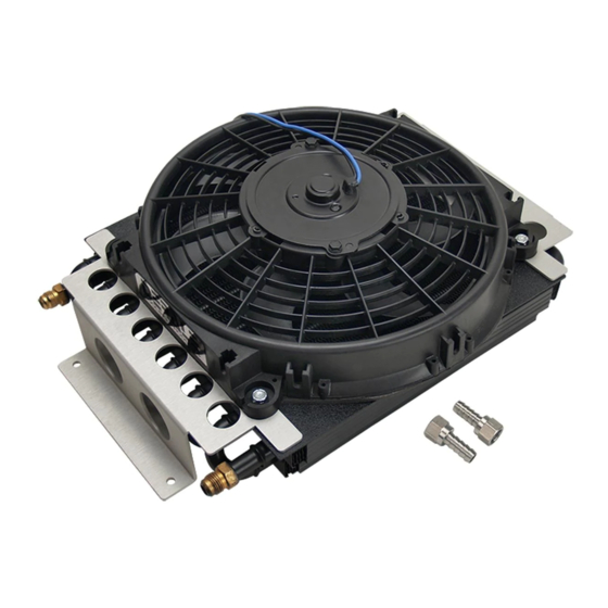
KIT CONTENTS
QTY. DESCRIPTION
1
Oil Cooler Assembly
2
-6AN Female x 3/8" Hose Barb Adapter
RECOMMENDED FOR
Transmission
Power Steering
PRE-INSTALLATION
Important:
The Electric Fan comes from the factory with a product label installed on one end of the fan shroud. Before installation
check the product label to confirm airflow direction & positive electric fan lead color. Airflow direction will be shown with an arrow.
This fan is factory setup for PULLER applications
Changing airflow direction
To change the airflow direction from the factory setting:
1. Using a 7/16" Socket & Ratchet, remove the four 1/4-20 lock
nuts holding the Electric Fan onto the Oil Cooler Assembly.
2. Remove the Nut or Clip that holds the electric fan blade onto
the motor shaft.
3. Carefully remove the fan blade from the motor shaft.
Note:
This is an interference fit and requires some effort.
4. Flip the fan blade upside down and reinstall onto the motor
shaft. Make sure the roll pin on the motor shaft is aligned with
the slot on the fan blade.
5. Reinstall nut or clip on motor shaft.
6. Reinstall the Electric Fan onto the Oil Cooler Assembly.
COOLER LOCATION
The purpose of a remote mount cooler is to be able to mount the cooler away from the front of the vehicle therefore not blocking
airflow to the radiator/condenser. This cooler can be mounted anywhere space permits. Always keep in mind that the cooler still
needs access to airflow to perform at its peak.
COOLER INSTALLATION
The Oil Cooler Assembly was manufactured with AN fittings. Included in this kit are two adapter fittings which allow the AN fitting to be
converted to hose barb. (See Diagram #1)
1. Hold the Oil Cooler Assembly in the desired location.
2. Using a marker, mark the four hole locations.
3. Using a drill and 9/32" drill bit, drill the four mounting holes.
4. Using 1/4"-20 Bolts, 1/4" Washers & 1/4" Lock Nuts (Not Supplied) attach the Oil Cooler Assembly.
ROUTING HOSES
Note:
The Cooler core will flow in either direction, there is no specified inlet or outlet port.
Warning:
When routing hoses, be sure to keep all hoses away from sharp edges, moving parts and hot engine components.
Hoses should be routed carefully and should not be bent in less than a 5" radius.
Important:
A kinked hose will restrict flow and could cause failure.
WIRING
(See Diagram # )
Specifications- Electric Fan rating:
Important:
Before beginning reference the Product Label on the Electric Fan
shroud for the factory PULLER fan configuration Positive wire color. If you wish to
configure the fan opposite of the factory PULLER setting, The Positive (+) and
Negative (-) wires MUST be switched.
Hook the Positive (+) wire to a switched 12 volt source (Manual Switch or Thermostat).
Hook the Negative (-) wire to a good chassis Ground (-).
Warning: Installation of accessories should only be undertaken by those with mechanical knowledge and are familiar with working on
vehicles. Always use eye protection (goggles, safety glasses or shield). Park the vehicle in a well lit area, on level ground and apply the
parking brake. Only work on a cold vehicle that has been sitting overnight, failure to do so will result in severe burns and injury. Before starting
the vehicle, make sure no tools or any other items are left under hood that could interfere with or be drawn into moving parts of the engine.
Failure to follow instructions can lead to severe damage and personal injury.
Derale Performance, Los Angeles, CA
Fuel
(MOUNTING HARDWARE NOT INCLUDED)
2
5.3 Amps
INSTALLATION INSTRUCTIONS
ELECTRA-COOL REMOTE COOLER
PART # 13700 & 13720
Standard Screw Driver
or 5/16" Nut Driver
7/16" Socket & Ratchet
Open End Wrench's
Always use backup wrenches when tightening fittings.
The AN fittings supplied in this kit do not require any thread
sealant. (See Diagram #1)
Diagram #1
Diagram #1
800.421.6288
TOOLS NEEDED
Teflon Tape
Razor Knife
Marker
IMPORTANT
Backup
DO NOT TIGHTEN WITHOUT
Wrench
BACKUP WRENCH!
Diagram #2
Diagram #2
Inlet
12V
Positive (+)
www.derale.com
Drill
9/32" Drill Bit
WARNING:
Ground
13700-13720-InstructionSheet
Advertisement
Table of Contents

Need help?
Do you have a question about the 13700 and is the answer not in the manual?
Questions and answers