Table of Contents
Advertisement
Quick Links
Advertisement
Table of Contents

Summary of Contents for Aqualine II WS1-Series
- Page 1 Water Softener System Installation, Operation & Maintenance Manual...
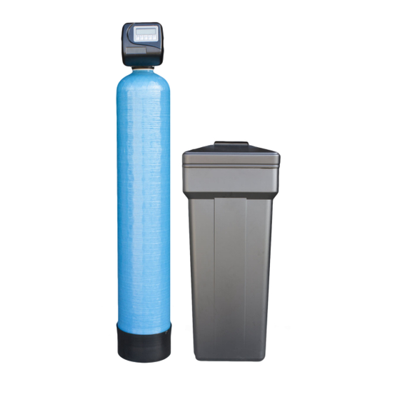
- Page 2 • 12 Volt Transformer Provides Safe and Easy Installation • Provides Optimum Service And Backwash Rates • Treated Water Regenerant Refill The Aqualine II WS1- Series Control Valve Specifications Inlet/Outlet 1", ..........
-
Page 3: Job Specification Sheet
Capacity of Unit Type of Media Cubic Feet Installing Dealer The Aqualine II WS-1 Series Control Valve Thank you for purchasing one of the most versatile Concerned with power failures? The control valve and simplistic water conditioners available. Your remembers all settings for two hours if the power new water conditioner is designed to provide you goes out. -
Page 4: Pre-Installation Checklist
Pre-Installation Checklist 1. Inspect the unit carefully for damage or shortage. 4. A bypass valve should be provided. 2. The unit should be located close to a clean 5. A minimum of 20 psi of water pressure is required working drain and connected according to local for the valve to operate effectively. -
Page 5: Control Start-Up Procedures
Control Start-Up Procedures The following outline includes a brief description of the functions of the buttons found on your control valve. A more detailed outline is included within this service manual. Button Functions The “SET CLOCK” button allows you to set the time of day, cancel out of the pro- gramming mode and saves changes when you are in the programming mode. -
Page 6: Program Setup
Program Setup NOTE: The programming on this page is for the programmable cycle valves only. To determine if the control valve has programmable cycles, press “NEXT” and “REGEN” simul- taneously. The board version will appear, if the board version starts with a “1” it is a standard electronics board, go to page 8 to continue setting up the control valve. - Page 7 Downflow Softener Program Codes NOTE: The program codes listed on this page and the following page are for the programable cycle valves only, and should be used only as a guideline. Any program code listed can be applied to a softener or filter application for CS controls. Program Code Main Piston Backwash...
- Page 8 IMPORTANT: The program codes listed on this page are for the programable cycle valves only, and should be used only as a guideline. Any program code listed can be applied to a softener or filter application for CS controls. Upflow Softener Program Codes for 1" or 1.25" CS Control Program Code Main Piston Backwash...
- Page 9 Control Start-Up Procedures Set Hardness The HARDNESS is entered into the control valve by pressing the “NEXT” and buttons simultaneously for 3 seconds. The default HARDNESS setting is 20. The buttons adjust the HARDNESS from 1 to 150. Press the “NEXT” button to advance to the SET DAY OVERRIDE function.
- Page 10 Control Start-Up Procedures Start an Immediate Extra Cycle An IMMEDIATE EXTRA CYCLE can be initiated by simply pressing and holding the “REGEN” button for 3 seconds. The system will begin to regenerate immediately. Fast Cycle Valve thru Regeneration Once an IMMEDIATE EXTRA CYCLE is initiated by press- ing and holding the “REGEN”...
-
Page 11: Final Setup
Control Start-Up Procedures Final Setup With proper valve operation verified: C. With the valve in SERVICE, check that there is about 1.0" of water above the grid in the brine tank, if used. A. Add water to the top of the air check. Manually step the valve to the BRINE Mode and allow the valve to D. - Page 12 Control Start-Up Procedures Immediate Regeneration Valves With Days Between Control Operation During Programming Regeneration Override Set The control will only enter the Program Mode with the When the valve reaches its set Days Since Regeneration valve in Service. While in the Program Mode the control Override value a regeneration cycle will be initiated will continue to operate normally monitoring water usage immediately.
-
Page 13: Flow Diagrams
Flow Diagrams Service Backwash... - Page 14 Flow Diagrams Downflow Brine Upflow Brine...
- Page 15 Flow Diagrams Rinse Fill...
- Page 16 Front Cover & Drive Assemblies Part No. Description Quantity C3175-01 Front Cover ASSM. C3107-01 Motor C3106-01 Drive Bracket & Spring Clip * Drawing number parts 2 C3108 PC Board through 6 C3108CS CS Version PC Board may be purchased as a complete C3108TC PC Board (Time Clock) assembly, part C3002.
- Page 17 Drive Cap Piston, & Stack Spacer Assembly Part No. Description Quantity C3005 Spacer Stack Assembly C3004 Drive Cap ASSM. C3178 C-Series Backplate C3011* Piston Downflow Assm. C3011-01* Piston Upflow Assm. C3174 Regenerant Piston C3135 O-ring 228 C3180 O-ring 337 C3105 O-ring 215 (Distributor Tube) 1-1/2"...
- Page 18 Injector Screen, Plug, & O-ring Assembly Part No. Description Quantity C3175-01 Front Cover ASSM. C3176 Injector Cap C3152 O-ring 135 CINJ-SCREEN Injector Screen CINJ-PLUG Injector Assm. Z Plug CINJ-A Injector Assm. A Black CINJ-B Injector Assm. B Brown CINJ-C Injector Assm. C Violet CINJ-D Injector Assm.
- Page 19 Refill & Refill Port Plug Part No. Description Quantity C3195-01 Refill Port Plug Assm. C4615 Elbow Locking Clip BCF03TS Polytube Brass Insert 3/8 FL19625 3/8 Nut C4613 Elbow Cap 3/8 C3163 0-ring 019 C3165-01 RFC Retainer Assm. C3182 **This part is required for backwash only systems...
- Page 20 3/4" Drain Line Flow Control Assembly Part No. Description Quantity C3195-01 Refill Port Plug Assm. H4615 Elbow Locking Clip V3158-01 Drain Elbow æ Male ASSM. V3163 0-ring 019 V3159-01 DLFC Retainer ASSM. WASHER07-0.7 3/4" DLFC - 0.7 gpm One DLFC WASHER07-1.0 3/4"...
- Page 21 1" Drain Line Flow Control Assembly Part No. Description Quantity H4615 Elbow Locking Clip V3008-02 WS1 Drain FTG 1 Straight V3166 WS1 Drain FTG Body 1 V3167 WS1 Drain FTG Adapter 1 V3163 0-ring 019 V3150 WS1 Split Ring V3151 WS1 Nut 1"...
-
Page 22: Water Meter & Meter Plug
Water Meter & Meter Plug Part No. Description Quantity C3151 Nut 1" QC C3003* Meter ASSM. C3118-01 Turbine ASSM. C3105 0-ring 215 C3003-01 Meter Plug ASSM. *Order number C3003 includes C3118-01 and C3105. -
Page 23: Installation Fitting Assemblies
Installation Fitting Assemblies C0710-PVC – 3/4" x 1" PVC Solvent 90° Assembly C10-PVC – 1" PVC Male NPT Elbow Assembly Part No. Description Qty. Part No. Description Qty. C3151 Nut 1" Quick Connect C3151 Nut 1" Quick Connect C3150 Split Ring C3150 Split Ring C3105... -
Page 24: Bypass Valve
Bypass Valve Part No. Description Quantity C3151 Nut 1" Quick Connect C3150 Split Ring C3105 O-Ring 215 C3145 Bypass 1" Rotor C3146 Bypass Cap C3147 Bypass Handle C3148 Bypass Rotor Seal Retainer C3152 O-ring 135 C3155 O-ring 112 C3156 O-ring 214... - Page 25 Wrench Although no tools are necessary to assemble or disassemble the valve, the wrench (shown in various positions on the valve) may be purchased to aid in assembly or disassembly.
-
Page 26: Drive Assembly
Service Instructions Drive Assembly Remove the valve cover to access the drive assembly. left by pressing on the side of the upper right corner. This helps the drive gears mesh with the drive cap assembly. Disconnect the power source plug (black wire) from the The drive bracket is properly seated when it snaps under PC board prior to disconnecting the motor or water meter the latches on the drive back plate. - Page 27 Service Instructions Replace the valve cover. After completing any valve es the service piston position. The display should flash all maintenance, press and hold NEXT and REGEN buttons wording, then flash the soft ware version (e.g. 154) and for 3 seconds or unplug power source jack (black wire) then reset the valve to the service position.
- Page 28 Service Instructions can be compressed it is easier to use a blunt object (5/8" to 1- Reattach the drive cap assembly and piston(s) and the drive 1/8" in diameter) to push the center of the assembly into the assembly. control valve body. The assembly is properly seated when at After completing any valve maintenance, press and hold least four threads are exposed (approximately 5/8").
-
Page 29: Water Meter Or Meter Plug
Service Instructions Water Meter or Meter Plug The water meter assembly is connected to the PC board by a control valve body and the meter. When the meter is part way wire. If the entire water meter assembly is to be replaced, out it is easy to remove the water meter from the housing. -
Page 30: Valve Identification
Valve Identification 1" Valve with 1.05" Distributor Tube Opening Identification Spacer Color: Grey 1.25" Black Plug 1.25" Note: The downflow piston is a solid amber color. The upflow piston is black and amber. " Valves with 1.32" Distributor Tube Opening Identification Spacer Color: Black 1.5"... -
Page 31: Troubleshooting Procedures
Trouble Shooting Procedures a. Transformer unplugged a. Connect power b. No electric power at outlet b. Repair outlet or use working outlet Timer does not display time of day c. Defective transformer c. Replace transformer d. Defective PC board d. Replace PC board a. - Page 32 Troubleshooting Procedures a. Motor not operating a. Replace motor b. No electric power at outlet b. Repair outlet or use working outlet c. Defective transformer c. Replace transformer 6. Control valve stalled in d. Defective PC board d. Replace PC board regeneration e.
Need help?
Do you have a question about the WS1-Series and is the answer not in the manual?
Questions and answers