Advertisement
Quick Links
WinKey USB SMT Assembly Guide
This document describes the assembly and testing of the K1EL Winkey USB Keyer Kit with a
version 01 SMT PCB. In this new design, surface mount components were used where ever
possible. These parts are pre-soldered to the PC board and tested at the factory. Assembly is
fairly simple and consists of soldering a few switches, connectors, and two wires. The builder
then performs final assembly and testing. Please read instructions before starting, there are
several steps that must be followed exactly as described.
WinKey SMT PCB Bill of Materials
QTY
Ref Designator
4
S1, S2, S3, S4
3
Plastic Push Cap
1
Plastic Push Cap
1
J1
1
J3
1
J6
1
SP1
1
RX1
1
KX1
1
WK-USB SMT PCB
2
WK_USB Enclosure
1
Misc
4
Screws
4
Screws
4
Rubber Feet
1
Piece
OB = Off Board, THS = Through hole soldered by builder
WinKey USB SMT Assembly and Operation Guide - Version 1.5 12/26/2017
Value
Description
SPST
Pushbutton Switch
Pushbutton Cap
Pushbutton Cap
1/8 phone jack
Connector
4 way RCA Jack
Connector
USB connector
Connector
Piezo
Speaker
10K
Potentiometer
Knob
Speed pot knob
Rev 01
PC Board
Aluminum Box
3xAAA
Battery holder
4-40 by ¼ inch
Bare metal
4-40 by ¼ inch
Black
Push in type
Velcro Tape
Adhesive
Version 1.5 12/26/2017
Package
PC mount
Black Square
Red Square
Paddle Input
Key/PTT Out
USB_B
Plastic Can
Pre-assembled
Attach PCB
Enclosure
Chk
THS
OB
OB
THS
THS
THS
THS
OB
OB
OB
OB
OB
OB
OB
Pg 1
Advertisement

Summary of Contents for K1EL WinKey
- Page 1 WinKey USB SMT Assembly Guide Version 1.5 12/26/2017 This document describes the assembly and testing of the K1EL Winkey USB Keyer Kit with a version 01 SMT PCB. In this new design, surface mount components were used where ever possible. These parts are pre-soldered to the PC board and tested at the factory. Assembly is fairly simple and consists of soldering a few switches, connectors, and two wires.
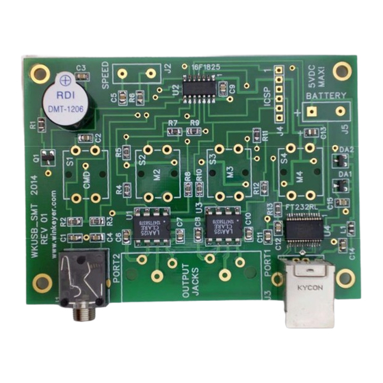
- Page 2 2) Even though the WKUSB PCB has a solder mask, it’s easy to inadvertently bridge two pads together. Please solder carefully, most kits returned for repair have soldering errors. Figure 1 – WKUSB PCB as shipped with kit WinKey USB SMT Assembly and Operation Guide - Version 1.5 12/26/2017 Pg 2...
- Page 3 There are four holes, two pairs with different spacing. Rotate the speaker to find the pair that fits. Peel off the protective film covering the top of the speaker. Figure 2 – J1, J6, and SP1 installed WinKey USB SMT Assembly and Operation Guide - Version 1.5 12/26/2017 Pg 3...
- Page 4 Don’t let this happen, it is very difficult to recover from this mistake. Figure 4 – Watch out !! Bent pin on RCA connector block WinKey USB SMT Assembly and Operation Guide - Version 1.5 12/26/2017 Pg 4...
- Page 5 Don’t forget to trim the connector leads after soldering. Figure 5 – Put a dab of glue here Figure 6 – And a dab of glue here WinKey USB SMT Assembly and Operation Guide - Version 1.5 12/26/2017 Pg 5...
- Page 6 J2. If you don’t plan on using the speed pot short the two pads of J2 with a short piece of resistor lead. Figure 8 – Speed Pot Connections WinKey USB SMT Assembly and Operation Guide - Version 1.5 12/26/2017 Pg 6...
- Page 7 3) Safety guidelines outlined in this document are not followed. 4) The K42 kit is modified in any way. K1EL cannot be held responsible in these or other similar events. WinKey USB SMT Assembly and Operation Guide - Version 1.5 12/26/2017 Pg 7...
- Page 8 Carefully wash excess flux off the board. WinKey USB SMT Assembly and Operation Guide - Version 1.5 12/26/2017 Pg 8...
- Page 9 RCA jacks so that they are centered in the back panel holes. Install four 4-40 screws to hold the top cover in place. 7) This completes the enclosure assembly. WinKey USB SMT Assembly and Operation Guide - Version 1.5 12/26/2017 Pg 9...
- Page 10 250V or higher to prevent shorting due to very high potentials. Even with good filtering the Winkey PCB is susceptible to problems caused by high RF potentials in the shack. Please observe standard RF grounding precautions to reduce RF at the operation position.
- Page 11 WinKey USB SMT Assembly and Operation Guide - Version 1.5 12/26/2017 Pg 11...
- Page 12 WinKey USB SMT Assembly and Operation Guide - Version 1.5 12/26/2017 Pg 12...
- Page 13 WinKey USB SMT Assembly and Operation Guide - Version 1.5 12/26/2017 Pg 13...
- Page 14 Winkey SMT PCB Rev 01 Layout Figure 13 – WinKey USB SMT PCB Check Plot Figure 14 – WinKey USB PCB Silkscreen WinKey USB SMT Assembly and Operation Guide - Version 1.5 12/26/2017 Pg 14...
- Page 15 Figure 15 - WinKey SMT USB PCB Component Side Figure 16 - WinKey USB PCB Solder Side WinKey USB SMT Assembly and Operation Guide - Version 1.5 12/26/2017 Pg 15...
- Page 16 8) You can not run WK3MGR when another application is connected to WKUSB. 9) When the host application closes WKUSB, standalone operation is restored and the EEPROM settings are reloaded. WinKey USB SMT Assembly and Operation Guide - Version 1.5 12/26/2017 Pg 16...
- Page 17 Precautions when connecting kit to a rig ..................10 Figure 12 – Back Panel View of Output Ports ................10 Figure 13 – WinKey USB SMT PCB Check Plot ............... 14 Figure 14 – WinKey USB PCB Silkscreen ................. 14 Figure 15 - WinKey SMT USB PCB Component Side ...............
Need help?
Do you have a question about the WinKey and is the answer not in the manual?
Questions and answers