
Summary of Contents for Mini-Circuits PWR-SEN-6G+
- Page 1 User Guide & Installation Instructions USB Power Sensor PWR-SEN-6G+ ISO 9001 ISO 14001 AS 9100 CERTIFIED P.O. Box 350166, Brooklyn, New York 11235-0003 (718) 934-4500 Fax (718) 332-4661...
-
Page 2: Table Of Contents
Installation Instructions and User Guide Table of Contents: Introduction: Performance: Installation Instructions Measurement Instructions Software License agreement Support Centers World Wide P.O. Box 350166, Brooklyn, New York 11235-0003 (718) 934-4500 Fax (718) 332-4661 ISO 9001 ISO 14001 AS 9100 CERTIFIED... -
Page 3: Introduction
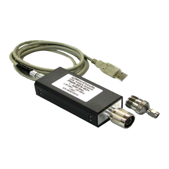
Not any more. Mini-Circuits’ has developed a Universal Serial Bus (USB) enabled Power Sensor PWR-SEN-6G+ that breaks away from that norm. -
Page 4: Performance
Performance Features • Operating frequency range of 1 MHz to 6 GHz • 50 dB dynamic range, -30 dBm to +20 dBm • Good VSWR, 1.1:1 (typical) • Accuracy: ±0.15 dBm (typical) • Linearity at 25 C is ±0.1 dBm (typical) •... -
Page 5: Installation Instructions
Excel and Text files: any result which exceeds limit will be marked by an asterisk “*”. Getting Started…Software Setup Insert the Mini-Circuits USB power sensor installation CD into the CDROM device. If installation does not start automatically, run install.exe from <CD drive> root directory. - Page 6 Getting Started…Software Setup (continued) The installation program will launch, to install Click on”OK” in the “Mini-Circuits USB Power Meter Setup” message box, see Figure 4. Figure 4: Mini-Circuits USB Power Meter Setup Window The default directory for the program setup is “C:\Program Files\USB Power Meter\”.
- Page 7 The Program Group message box will appear and you may change the Program Group name or leave it as "Mini-Circuits USB Power Meter”. Click on “Continue” to proceed, see Figure 6. Figure 6: Program Group Window You have completed the Mini-Circuits USB Power Meter setup successfully,Click ”OK”, see Figure 7.
- Page 8 Installation of USB Power Sensor Hardware With the Mini-Circuits USB power sensor installation CD into the CDROM device. Connect the power sensor to the PC USB port. Select “No, not this time“ The New Hardware Wizard window will appear, and Click Next to continue, see Figure 8.
- Page 9 (floppy, CD-ROM…)” box. Click and Check ”Include this location in the search:” box. Click on Browse to choose location of the drivers for the Mini-Circuits USB Power Sensor on the installation CD, <drive>:\drivers ( where <drive> is your CD-ROM drive letter, for example;...
-
Page 10: Measurement Instructions
Plug the push-pull connector in to the end of the USB Power Sensor. Plug the USB connector in to the USB port on the computer. Run the Mini-Circuits USB Power Meter so ftware. In few seconds the main screen will appear, see Figure 13, and the Power Meter is immediately available for measurements. - Page 11 Figure 14: Power Meter Recording window Specification Limit Settings Upper and lower test power results limits may be defined in the “Test Spec Dn” (lower limit) and Test Spec Up (upper limit). Data point deviations from these limits are indicated on the recorded test results report.
- Page 12 Text Data File Upon clicking “Open Data File”, a text file window will appear with the recorded data, see Figure 16. The data record options defined by the user will be shown on this text file, for example Date, Time, Frequency, upper and lower Power limits, Temperature. Data results which are outside of the upper and lower Power limits defined will be marked with an asterisk “*”.
- Page 13 Additional Power Meter Software Features Data Averaging: In cases when the measured signal is not stable, it is possible to display the test result based on the average of a number of measurements. The number of √ measurements that the averaging is base is defined by the user. A check mark “ ” is put in unt”...
- Page 14 Offset Value: This feature allows the user to adjust the readings to compensate for √ external Attenuation on the line being tested. A check mark “ ” is put in the “Offset Val.” box, see Figure 19, and Attenuation offset value is typed into the “Offset Val.” window. Reset Connection: If the Power Sensor is unplugged from the USB port, to continue taking readings, the Power Sensor should be plugged back into the USB port and click the...
- Page 15 Compact View The Compact View allows the user view the serial number of each Power Sensor, Frequency, and Power reading, see Figure 21. To change the Frequency of one of the Power Sensors, click on the screen and a full screen view will be shown, where the relevant Frequency may be changed.
-
Page 16: 5.0 Software License Agreement
Purchaser or its representative does not agree to these Terms of Use, neither Purchaser nor its representative can use the Software. Mini-Circuits may amend these Terms of Use from time to time, without notice, which amendments will be posted on Mini-Circuits’ website at www.minicircuits.com (the “Website”) and will become effective upon posting. - Page 17 (collectively, the “Software IP”) are the sole and exclusive property of Mini-Circuits and that Purchaser has no right, title, or interest in any of the Software IP. Purchaser owns only the media on which the Software IP is recorded, but Mini-Circuits retains sole and exclusive ownership of the Software IP itself.
-
Page 18: Support Centers World Wide
Purchaser’s purchase of the Part and installation and use of this Software. With regards to the Terms of Use, Mini-Circuits shall have the right, at its sole discretion, to modify, add or remove any terms and conditions of the Terms of Use from time to time without notice or liability to Purchaser.
Need help?
Do you have a question about the PWR-SEN-6G+ and is the answer not in the manual?
Questions and answers