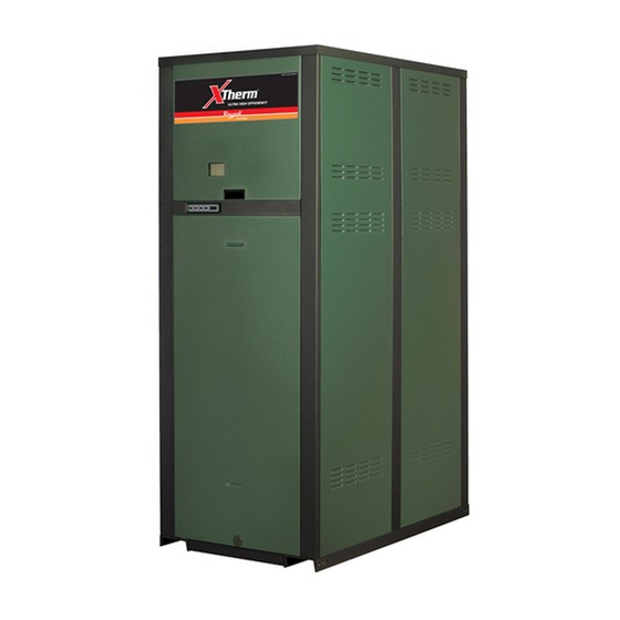
Summary of Contents for Raypak MVB 503-2003
- Page 6 MBTUH Water Conn. Model Input Conn. (NPT) (NPT) Max. Min. 1003 2-1/2 1-1/4 1253 1250 312 2-1/2 1-1/4 1503 1500 375 2-1/2 1-1/4 1753 1750 438 2-1/2 2003 1999 500 2-1/2 HIGH VOLTAGE ELECTRICAL CONNECTIONS Vent Size (in.) Flue Intake...
- Page 7 Water temperature over 125°F can cause instant severe burns or death from scalds. Children, disabled, and elderly are at highest risk of being scalded. See instruction manual before set- ting temperature at water heater. Feel water before bathing or show- ering.
- Page 8 Minimum Clearance Heater from Combustible Side Surfaces Floor* 0” Rear 12” Right Side 1” Left Side 1” 0” Front Open Vent 1” Minimum Service Clearance 0” 24” 1” 1” 10” 24” 1”...
- Page 9 Venting not shown for clarity. Heater must be vented per instructions in this manual...
- Page 10 Clearance above grade, veranda, porch, deck, or balcony Clearance to window or door that may be opened Clearance to permanently closed window Vertical clearance to ventilated soffit located above the terminal within a horizontal dis- tance of 2 ft (61cm) from the centerline of the terminal Clearance to unventilated soffit Clearance to outside corner...
- Page 14 must...
- Page 15 20°F T 30°F T Model P (ft) 1003 12.0 1253 20.9 1503 1753 2003 Min. Flow 40°F T P (ft) P (ft) 10.2 16.0 22.5 13.4 32.0 18.9 Max. Flow P (ft) P (ft) 11.3 13.8 18.6 22.2 25.5 13.4 27.2 18.9 32.0...
- Page 16 Soft (0-4 grains per gallon) Model T gpm 1003 6.0 2-1/2 7.2 1253 10.4 2-1/2 12.1 1503 16.0 2-1/2 18.5 1753 102 22.7 2-1/2 26.0 2003 116 32.0 2-1/2 36.1 SYSTEM SUPPLY SYSTEM RETURN Medium (5-15 grains per gallon) 12.0 2-1/2 21.0 2-1/2...
- Page 17 POOL THERMOSTAT FROM FILTER TO POOL CHEMICAL FEED...
- Page 18 Chemical imbalance can cause severe damage to the pool heater and associated equipment. Maintain the water chemistry according to the chart below. If the mineral content and dissolved solids in the water become too high, scale forms inside the heat exchang- er tubes, reducing heater efficiency and damaging the heater.
- Page 19 All chemicals must be introduced and completely dilut- ed into the pool or spa water before being circulated through the heater. Do not place sanitizing chemicals in the skimmer. High chemical concentrations will result when the pump is not running (e.g. overnight). Chlorinators must feed downstream of the heater and have an anti-siphoning device to prevent chemical back-up into the heater when the pump is shut off.
- Page 20 Manifold Gas Pressure Model (High Fire Values) Natural Gas Propane Gas -0.1 -0.4 1003 -0.8 1253 -1.6 1503 -2.4 1753 -0.4 2003 -1.0 -0.1 -0.1 -0.2 -0.2 -0.6 -0.1 -0.5...
- Page 21 FRONT WIRING PANEL LOW VOLTAGE ELECTRICAL CONNECTIONS BLACK CIRCUIT BREAKER WHITE GREEN GROUND A B C...
- Page 22 HIGH VOLTAGE WIRING LOCATOR DIMPLES FOR OPTIONAL COMPONENTS...
- Page 23 Combustion Exhaust Air Supply Configuration Vertical Venting From Inside Building (Non-Direct Venting) Horizontal Through- the-Wall Venting Vertical Venting From Outside Building (Direct Venting) Horizontal Through- the-Wall Venting Heater Venting Certified Category Materials Stainless Steel AL29-4C Combustion Air Inlet Material Galvanized Steel CPVC...
- Page 25 Certified Vent Size Model Vent (in.) Material 1003 Category IV 1253 (AL29-4C) 1503 1753 2003 Vertical Vent Combustion Air Height (Ft) Intake Pipe Material Min. Max. Galvanized Steel, PVC, ABS, CPVC Air Inlet Max. Length** (Ft) 6” Ø 8” Ø 10” Ø...
- Page 26 Vent Vent Pressure Model Size (in.) (in. WC) 1003 1253 1503 1753 2003 Volume of Flue Products (CFM)
- Page 31 MODULATING MODULATING MODULATING...
- Page 32 RAYPAK MODULATING TEMP CONTROL MODULATING OUTDOOR AIR SENSOR...
- Page 35 Item L External Input Modulation Offset Signal Modulating Control Item...
- Page 36 Code Condition System OK; No faults present Possible control fault; Check power 1 Flash Low air Flame in combustion chamber; 2 Flashes No call for heat 3 Flashes Ignition lockout 4 Flashes Low HSI current 5 Flashes Low 24 VAC 6 Flashes Internal fault;...
- Page 42 TO BURNER...
- Page 44 TO BURNER...
- Page 47 Does the power switch provide power to the control panel? Step 1 Is there a Call For Step 2 Is Disable connection intact? Does the combustion air Step 3 blower come on? Is 4-20mA present at the quick disconnects on the black and blue wires of the tem perature controlle r? Does F2 on ignition module have AC powe r?
- Page 53 SCOPE Raypak, Inc. (“Raypak”) warrants to the original owner that all parts of this heater which are actually manufactured by Raypak will be free from failure under normal use and service for the specified warranty periods and subject to the conditions set forth in this Warranty. Labor charges and other costs for parts removal or reinstallation, shipping and transportation are not covered by this Warranty but are the owner’s responsibility.
- Page 54 START-UP CHECKLIST FOR FAN-ASSISTED This start-up checklist is to be completely filled out by the service technician starting up the Raypak Boiler or Heater for the first time. All information may be used for warranty purposes and to ensure that the installation is correct.
- Page 56 www.raypak.com...


Need help?
Do you have a question about the MVB 503-2003 and is the answer not in the manual?
Questions and answers