Table of Contents
Advertisement
Quick Links
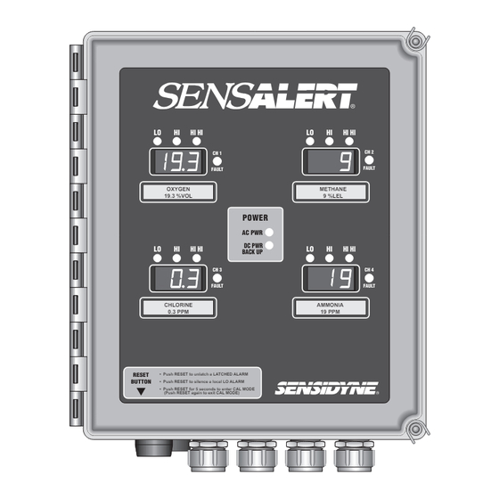
FOUR CHANNEL CONTROLLER
LO
LO
RESET
• Push RESET to unlatch a LATCHED ALARM
BUTTON
• Push RESET to silence a local LO ALARM
• Push RESET for 5 seconds to enter CAL MODE
Document No. 7013227M
HI
HI HI
CH 1
FAULT
OXYGEN
19.3 %VOL
POWER
AC PWR
DC PWR
HI
HI HI
BACK UP
CH 3
FAULT
CHLORINE
0.3 PPM
(Push RESET again to exit CAL MODE)
(800) 451-9444 • (727) 530-3602 • Fax: (727) 539-0550
web: www.sensidyne.com • e-mail: info@sensidyne.com
(Revision H)
LO
HI
HI HI
CH 2
FAULT
METHANE
9 %LEL
LO
HI
HI HI
CH 4
FAULT
AMMONIA
19 PPM
Sensidyne, LP
1000 112th Circle N, Suite 100
St. Petersburg, Florida 33716 USA
Advertisement
Table of Contents

Summary of Contents for Sensidyne Sensalert
- Page 1 • Push RESET for 5 seconds to enter CAL MODE (Push RESET again to exit CAL MODE) Sensidyne, LP 1000 112th Circle N, Suite 100 St. Petersburg, Florida 33716 USA (800) 451-9444 • (727) 530-3602 • Fax: (727) 539-0550 web: www.sensidyne.com • e-mail: info@sensidyne.com...
-
Page 3: Packing List & Notices
SOFTWARE LICENSE The software included with the SensAlert is the property of Sensidyne, LP and shall remain the property of Sensidyne, LP in perpetuity. The soft- ware is protected by U.S. and international copyright laws and is licensed for specific use with the SensAlert Four Channel Controller. The user may NOT reverse-engineer, disassemble, decompile, or make any attempt to discover the source code of the software. -
Page 4: Table Of Contents
Channel Screens .................... 12 SECTION TWO: INSTALLATION Mounting & Wiring ..................... 15 2.1.1 Terminal Designations .................. 15 2.1.2 Jumpers ......................16 2.1.3 Fuses ......................16 2.1.4 Potentiometers ....................16 Wiring Procedure ......................18 Initial Start-Up ......................21 PRELIMINARY Sensidyne Document No. 7013227M (Rev H) - Page 5 SECTION SIX: MAINTENANCE & SERVICE Adjusting the Output ....................34 Replacing the Power Supply ..................34 Replacing the Display PCB ..................35 Replacing the Bottom PCB ..................35 SECTION SIX: PARTS LIST • Controller Parts ........................36 PRELIMINARY Sensidyne Document No. 7013227M (Rev H)
- Page 6 Controller Mounting ....................19 Terminal Wiring Guide .................... 20 Wiring to a SensAlert Transmitter (with Intrinsic Safety Barrrier) ......22 Wiring to a SensAlert Transmitter (without Intrinsic Safety Barrrier) ....23 Wiring to a non-SensAlert Transmitter (without Intrinsic Safety Barrrier) .... 24 Section Three: Operation Entering a Password ....................27...
-
Page 7: Warnings
DO NOT attempt to repair or modify the instrument, except as specified in the Operation and Service Manual. Contact the Sensidyne Service Department to arrange for a Returned Material Authorization (RMA). -
Page 8: Overview
This manual provides specific information concerning event needs to be relayed to a peripheral device, such the installation, operation, and maintenance of the as a building fire alarm system. The SensAlert Control- Sensidyne SensAlert Controller. ler displays can display gas levels in either ppm, %vol, or %LEL, depending on the installed sensor. -
Page 9: Components
Terminal wiring designations are described in Section Two. The Bottom PCB also contains jumpers, AC & DC fuses, and a current limiting 4 channel power supply. PRELIMINARY Sensidyne Document No. 7013227M (Rev H) -
Page 10: Display Pcb
HI HI HI HI DC BACK UP OXYGEN CHLORINE CARBON MONOXIDE 19.3 %VOL .3 PPM 19 PPM Operator Buttons CHANNEL SELECT NEXT SELECT DOWN Hinged Standoff Mounting (under PCB) Screw Figure 1.1 Display PCB PRELIMINARY Sensidyne Document No. 7013227M (Rev H) -
Page 11: Operator Buttons
(see figure 1.3). button also is used to accept a value after SELECT it has been changed (e.g., a new alarm setting). It is similar to the RETURN/ENTER key on a keyboard. PRELIMINARY Sensidyne Document No. 7013227M (Rev H) -
Page 12: Controller Screens
4-digit password to access the Set Alarms, and an Alarm Relay Check. Set-Up, and Diagnostics screens in any of the 4 chan- nels. The unit is shipped from the factory without a password. PRELIMINARY Sensidyne Document No. 7013227M (Rev H) -
Page 13: Controller Menu System: Main Screens
SENSALERT FOUR CHANNEL CONTROLLER PRELIMINARY Sensidyne Document No. 7013227M (Rev H) -
Page 14: Controller Menu System: Individual Channel Screens
• Relay Check • Set Cal Delay • Resume • Change Password • RS-485 Addr • Alarm Latching • Energize Relay • Adjust Zero • Resume Figure 1.3 Controller Menu System: Individual Channel Screens PRELIMINARY Sensidyne Document No. 7013227M (Rev H) -
Page 15: Mounting & Wiring
INSTALLATION 2.1 MOUNTING & WIRING • Transmitter Power To Sensors (J8-J11) The SensAlert Controller is designed to be wall This terminal is used to wire the controller to the mounted. Four mounting feet are supplied. The feet transmitter. A simplified wiring diagram showing how... -
Page 16: Jumpers
Counterclockwise adjustments decrease it. The potentiometers are designated as follows: VR1 = Channel 1 VR2 = Channel 2 VR3 = Channel 3 VR4 = Channel 4 PRELIMINARY Sensidyne Document No. 7013227M (Rev H) -
Page 17: Controller Wiring: Bottom Pcb
DC Connector AC Connector to PCB to PCB Safety Ground [install ground wire from power source here] 24 VDC Battery DC Fuse, 3 amp (F1) Back-Up (J3) Figure 2.1 Controller Wiring: Bottom PCB PRELIMINARY Sensidyne Document No. 7013227M (Rev H) -
Page 18: Wiring Procedure
11) Close the Display PCB and secure it with the mounting screws. 12) Close the controller cover and secure the quick release latches. 10-32 screw Mounting Foot Controller Back Figure 2.2 Attaching the Mounting Feet PRELIMINARY Sensidyne Document No. 7013227M (Rev H) -
Page 19: Controller Mounting
• Push RESET to silence a local LO ALARM • Push RESET for 5 seconds to enter CAL MODE (Push RESET again to exit CAL MODE) Quick-Release Reset Button Latch Alarm Buzzer EMT Connectors (optional) Figure 2.3 Controller Mounting PRELIMINARY Sensidyne Document No. 7013227M (Rev H) -
Page 20: Terminal Wiring Guide
Insert wire into Pull on terminal plug terminal plug to remove it from board MAIN BOARD Tighten terminal screw Install terminal plug on with flat blade screwdriver appropriate terminal block Figure 2.4 Terminal Wiring Guide PRELIMINARY Sensidyne Document No. 7013227M (Rev H) -
Page 21: Initial Start-Up
6) The unit will perform channel initialization for nel 1. each of the 4 channels. After initialization, the unit will begin Normal Operation. 7) If you want to adjust the output at this point, go to Section 6.1. PRELIMINARY Sensidyne Document No. 7013227M (Rev H) -
Page 22: Wiring To A Sensalert Transmitter (With Intrinsic Safety Barrrier)
NOTE 1: Twisted, stranded wire with shield (grounded on one end only) is recommended. Distance is in feet. To obtain distance in meters multiply by 0.3. Figure 2.5 Wiring to a SensAlert Transmitter (with Intrinsic Safety Barrier) PRELIMINARY Sensidyne Document No. 7013227M (Rev H) -
Page 23: Wiring To A Sensalert Transmitter (Without Intrinsic Safety Barrrier)
NOTE 1: Twisted, stranded wire with shield (grounded on one end only) is recommended. Distance is in feet. To obtain distance in meters multiply by 0.3. Figure 2.6 Wiring to a SensAlert Transmitter (without Intrinsic Safety Barrier) PRELIMINARY Sensidyne Document No. 7013227M (Rev H) -
Page 24: Wiring To A Non-Sensalert Transmitter (Without Intrinsic Safety Barrrier)
NOTE 1: Twisted, stranded wire with shield (grounded on one end only) is recommended. Distance is in feet. To obtain distance in meters multiply by 0.3. Figure 2.7 Wiring to a non-SensAlert Transmitter (without Intrinsic Safety Barrier) PRELIMINARY Sensidyne Document No. 7013227M (Rev H) -
Page 25: Main Screen
If the number does not match, you are given two more chances to enter the correct password. If the correct password is not entered on the third try access is de- nied (refer to Figure 3.1). PRELIMINARY Sensidyne Document No. 7013227M (Rev H) -
Page 26: Entering Calibration Mode
Set-Up Menu. See Section 5.1.2. Calibra- tion delay can range from 1–30 minutes. The screen indicates the number of minutes the alarms will be suppressed while calibration is being per- formed. PRELIMINARY Sensidyne Document No. 7013227M (Rev H) -
Page 27: Entering A Password
PASSWORD INVALID PASSWORD INVALID P L E A S E T RY A G A I N A C C E S S D E N I E D Figure 3.1 Entering A Password PRELIMINARY Sensidyne Document No. 7013227M (Rev H) -
Page 28: Changing Alarm Settings
(see below). LO ALARM HIHI 25 PPM Use the buttons to change the setting. DOWN To return to the main screen, scroll down to “Resume” and press SELECT LO ALARM 30 PPM PRELIMINARY Sensidyne Document No. 7013227M (Rev H) -
Page 29: Set-Up (Menu #3)
If the channel is changed from “en- abled” to disabled” the channel will show the following screen. CHANNEL DISABLED To return to the main screen, scroll down to “Resume” and press SELECT PRELIMINARY Sensidyne Document No. 7013227M (Rev H) -
Page 30: Changing The Password
4) Repeat the procedure for the 3rd digit. 5) Repeat the procedure for the 4th digit. When you press the entire 4-digit password is now set. SELECT A confirmation appears showing you the new pass- word. PRELIMINARY Sensidyne Document No. 7013227M (Rev H) -
Page 31: Changing A Password
CHANGE PASSWORD “ 3 7 4 ” SELECT Push SELECT to set final digit and accept new password code PASSWORD CHANGED TO “ 3 7 4 8 ” Figure 5.1 Changing a Password PRELIMINARY Sensidyne Document No. 7013227M (Rev H) -
Page 32: Setting Alarm Latching
Adjust Zero, DOWN then press SELECT NOTE Adjusting zero for oxygen sensors sets the display to 20.9% vol To return to the main screen, scroll down to “Resume” and press SELECT PRELIMINARY Sensidyne Document No. 7013227M (Rev H) -
Page 33: Diagnostics (Menu #4)
LO ON SOFTWARE FAULT RETURN UNIT RELAY CHANNEL 1 HI ON If the unit fails the self test, contact Sensidyne Service. See Appendix E for information on returning products RELAY CHANNEL 1 for repair. HIHI ON To return to the main screen, scroll down to “Resume”... -
Page 34: Adjusting The Output
9) Install the four (4) mounting screws. 10) Reconnect the DC and AC connectors. 11) Swing close the Display PCB. 12) Install the two (2) mounting screws. 13) Close and latch the controller cover. PRELIMINARY Sensidyne Document No. 7013227M (Rev H) -
Page 35: Replacing The Display Pcb
14) Swing open the Display PCB and connect the rib- bon cable to the new Bottom PCB. 15) Swing the Display PCB closed and install the re- maining two (2) mounting screws. 16) Close and latch the controller cover. PRELIMINARY Sensidyne Document No. 7013227M (Rev H) -
Page 36: Controller Parts
& t i s & t i s " 4 & i r t i r r i r r i r r i r r s l i i r r PRELIMINARY Sensidyne Document No. 7013227M (Rev H) -
Page 37: Appendix A: Specifications
284 mm (W) x 325 mm (H) x 160 mm (D) Weight ............10.0 lbs (4.5 kg) Classification Intrinsic Safety Rating ........Designed to operate intrinsically safe SensAlert transmitters when installed with a Sensidyne I.S. barrier per wiring dia- gram. -
Page 38: Appendix Dtroubleshooting Guide
, t r a r t e t t . s r . t r t t i y f i n i t PRELIMINARY Sensidyne Document No. 7013227M (Rev H) -
Page 39: Returned Material Authorization
These options include initial training, on-site technical assistance, and full factory repairs. Sensidyne has developed several programs which offer options best suited to your applications and needs. For further information, contact the Sensidyne Service Department at the following numbers: 800-451-9444 •... - Page 40 ) t i i t c ) l a i r c i t p t a t l i o t s i p i t s l i p i t PRELIMINARY Sensidyne Document No. 7013227M (Rev H)
- Page 42 Sensidyne, LP 1000 112th Circle N, Suite 100 St. Petersburg, Florida 33716 USA (800) 451-9444 • (727) 530-3602 • Fax: (727) 539-0550 web: www.sensidyne.com • e-mail: info@sensidyne.com...
Need help?
Do you have a question about the Sensalert and is the answer not in the manual?
Questions and answers