Table of Contents
Advertisement
TitanMig Pulse 2700/3500/5000
Operation Manual
TitanMig Pulse 2700/3500/5000 MIG/TIG/Stick Welder
Model No. TMP2700, TMP3500, TMP5000 Issue. A 05/16
Operating manual
Brugsanvisning
Gebrauchsanweisung
Manual de instrucciones
Käyttöohje
Manuel d'utilisation
Manuale d'uso
Gebruiksaanwijzing
Bruksanvisning
Instrukcja obsługi
Manual de utilização
Инструкции по эксплуатации
Bruksanvisning
操作手册
EN
DA
DE
ES
FI
FR
IT
NL
NO
PL
PT
RU
SV
CN
Advertisement
Table of Contents
Troubleshooting

Summary of Contents for Headux TitanMig Pulse 2700
- Page 1 TitanMig Pulse 2700/3500/5000 Operation Manual Operating manual Brugsanvisning Gebrauchsanweisung Manual de instrucciones Käyttöohje Manuel d’utilisation Manuale d’uso Gebruiksaanwijzing Bruksanvisning Instrukcja obsługi Manual de utilização Инструкции по эксплуатации Bruksanvisning 操作手册 TitanMig Pulse 2700/3500/5000 MIG/TIG/Stick Welder Model No. TMP2700, TMP3500, TMP5000 Issue. A 05/16...
- Page 2 TitanMig Pulse 2700/3500/5000 Operators Manual Issue. A 0516...
- Page 3 Warranty will be considered void if this product has been altered, tampered or used in any manner contrary to customary usage or application. Full warranty details and conditions supplied with this product are shown in the back of this manual. TitanMig Pulse 2700/3500/5000 Operators Manual Issue. A 0516...
-
Page 4: Table Of Contents
MMAW (Stick) Welding……………………………………………………………………….42 GTAW (TIG) Welding………………………………………………….………………………..44 Software Updates……………………………………………………………………………….47 Add Funtions………………………………………………………………………………………54 Trouble Shooting…………………………………………………………………………………55 Mig Trouble Shooting………………………………………………………………………….55 MMAW (Stick) Trouble Shooting…………………………………………………………57 GTAW (TIG) Trouble Shooting……………………………………………………………..58 Electrical Trouble Shooting………………………………………………………………...59 Maintenance…………………………………………………………………………………..….60 Electrical Diagram……………………………………………………………………………….61 Warranty Terms & Conditions……………………………………………………………..62 TitanMig Pulse 2700/3500/5000 Operators Manual Issue. A 0516... -
Page 5: Safety Precautions
Do not weld on coated metals, unless the coating is removed from the weld area, the area is well ventilated, and while wearing an air-supplied respirator. The coatings on many metals can give off toxic fumes if welded. TitanMig Pulse 2700/3500/5000 Operators Manual Issue. A 0516... - Page 6 Do not work in atmospheres with high concentrations of combustible fumes, flammable gases and dust. Always check the work area half an hour after cutting to make sure that no fires have begun TitanMig Pulse 2700/3500/5000 Operators Manual Issue. A 0516...
- Page 7 Never allow the electrode, electrode holder or any other electrically “hot” parts to touch a cylinder. Keep your head and face away from the cylinder valve outlet when opening the cylinder valve. Always secure the cylinder safely. Never deface or alter any cylinder TitanMig Pulse 2700/3500/5000 Operators Manual Issue. A 0516...
-
Page 8: Emf Information
Damage can occur to the welding machine if not operated according to this manual. Failures and accidents due to such actions are not covered by warranty, nor can the producer be held responsible TitanMig Pulse 2700/3500/5000 Operators Manual Issue. A 0516... - Page 9 Symbol usage Means Warning! Watch Out! There are possible hazards with this procedure! The possible hazards are shown in the adjoining symbols. ▲ Marks a special safety message. This group of symbols means Warning! Watch Out! Possible ELECTRIC SHOCK, MOVING PARTS, and HOT PARTS hazards.
- Page 10 When making input connections attach proper grounding conductor first - double-check connections. Frequently inspect input power cord for damage or bare wiring replace cord immediately if damaged — bare wiring can kill. Turn off all equipment when not in use. ...
- Page 11 ARC RAYS can burn eyes and skin. Arc rays from the welding process produce intense visible and invisible (ultraviolet and infrared) rays that can burn eyes and skin. Sparks fly off from the weld. Wear a welding helmet fitted with a proper shade of filler to protect your face and eyes when welding or watching (see Safety Standards).
- Page 12 FLYING METAL can injure eyes. Welding, chipping, wire brushing, and grinding cause sparks and flying metal. As welds cool, they can throw off slag. Wear approved safety glasses with side shields even under your welding helmet. BUILDUP OF GAS can injure or kill. ...
- Page 13 CYLINDERS can explode if damaged. Shielding gas cylinders contain gas under high pressure. If damaged, a cylinder can explode. Since gas cylinders are normally part of the welding process, be sure to treat them carefully. Protect compressed gas cylinders from excessive heat, mechanical shocks, slag, open flames, sparks, and arcs.
- Page 14 STATIC (ESD) can damage PC boards. Put on grounded wrist strap BEFORE handling boards or parts. Use proper static-proof bags and boxes to store, move, or ship PC boards. MOVING PARTS can cause injury Keep away from moving parts. ...
-
Page 15: Preface
1.0 Preface 1.1 General Congratulations on choosing TitanMig Pulse welding machine. Used correctly, our products can significantly increase the productivity of your welding, and provide years of economical service. This operating manual contains important information on the use, maintenance and safety of our product. -
Page 16: Introduction
The TitanMig Pulse 2700 features an integral 4-roller drive. There is no longer an interconnecting hose pack between the power source and wire-feed unit. Its compact design makes the TMP 2700 particularly suitable for mobile applications on building sites or in repair workshops.. -
Page 17: Technical Specifications
1.3 Technical Specifications TMP 5000 TMP 3500 TMP 2700 Power Supply / Phases (V-Ph) AC380V±15%~50/60Hz 240 V 1 Phase Duty Cycle@40°c to AS/NZ60974 60% @ 350 Amps MIG 35% @ 275Amps MIG % @ 500 Amps MIG 60% @ 500 Amps MMA 60% @ 350 Amps MMA 60% @ 194Amps MMA Rated Output Power Rate... -
Page 18: Important Notes Before Use
1.4 Important notes before use ▲ Do not operate or install this equipment without thoroughly reading this manual and the safety precautions contained throughout. Save this manual and keep it handy for reference. Disconnect mains of the semi-automatic welding machine after finishing work or before a long break. ▲... -
Page 19: Overview Of Power Source
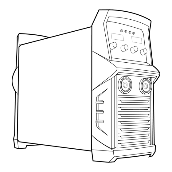
1.5 Overview of Power Source TitanMig 500 Shown (details will vary from model) Front View Power Source Front Panel Layout 1. Control panel 2. Welding Cable Connection 3. Earth Cable Connection Rear View 4. CO2 Heating Socket 5. Welding Cable Connection 6.Data Plate 7. -
Page 20: Overview Of Wire Feeder
1.5 Overview of Wire Feeder (TMP3500/5000 Only) HF10 Structure 1. Control Box 2. Spool Cover 3. Handle 4. Drive System 5. Gun Connector HF10 Drive System 1. Drive Gear 2. Wire Feed Rollers 3. Pressure Rollers 4. Pressure Rocker Arm 5. - Page 21 1.6 Description of the control panels Control Panel 1. Feeder inching button for feeding the wire electrode into the torch-hosepack without any flow of gas or curren 2. Adjusting dial for altering welding parameters. If the indicator on the adjusting dial is lit up, then the selected parameter is one that can be altered. 3.
- Page 22 parameter is selected 1) For MIG welding process: the inductance value 0 is recommended reference range. Value less than 0 give a rougher arc and increased stability. Value greater than 0 give a smoother arc and less spatter. 2) For pulse MIG welding process: The droplet transfer force will be increased according the inductance value changed from less than 0 to greater than 0.
- Page 23 17. Material button for selecting the filler metal and shielding gas to be used. Parameters SP1 and SP2 are reserved for additional materials. When a material is selected, the LED behind the relevant filler metal lights up. 18. Mode button for selecting the mode 2-step mode 4-step mode...
-
Page 24: Welding Panel , Storage & Recall
MIG/MAG standard synergic welding MIG/MAG single pulse synergic welding MIG/MAG double pulse synergic welding When a process is selected, the LED on the relevant symbol lights up. Save Button: For two purposes: store the welding parameters and startup Settings menu 21. -
Page 25: Welding Machine Setup
1.8 TMP welding machine startup Settings. Some welding parameters of TMP series welding machine could be adjusted through the startup Settings menu, and the operation process as following: 1) Press on key, and turn on the power switch of the machine at the same time. 2) After few seconds, it enters the Startup Settings Menu, and LED display "Preg"... -
Page 26: Welding Machine Status Display
1.9 TMP series welding machine status display TMP series welding machine can display some information and status of the welder. After startup welding, the LED will display the company LOGO, hardware, software version, 25 welding process, expert database material type and whether support DEVICENET and WIFI one by one. Operation process of the welding machine status display 1) Press to choose the display value as... -
Page 27: Installation
2.0 Installation Worker and working area protection Fumes and gases produced by welding are dangerous for your health. Ventilation in workplace must be adequate to remove all harmful fumes and gases but not too strong since it could remove the shielding gas flowing over work piece. -
Page 28: Output Connections
Mains supply – TMP 2700 Only The INPUT primary cable is supplied with machine. Connect the machine to mains according to your state legislation of where machine is being used. Connection can be effected through plug or direct wiring. Supply system should be protected at all times by the fuse stated in technical data section. -
Page 29: Operation
3.0 Operation Duty cycle and overheating Duty Cycle is percentage of 10 minutes that unit can weld at rated load without overheating. If unit overheats, thermostat(s) opens, output stops, and cooling fan runs. Wait fifteen minutes for unit to cool. Reduce amperage or duty cycle before welding. -
Page 30: Gmaw (Mig) Welding
3.1 GMAW (MIG) Welding Insert the welding torch into the “Euro connector for torch in MIG” output socket on the front panel of the wire feed unit, and tighten it. Install the wire spool on the spindle adapter of the wire feed unit. ... -
Page 31: Installation Of Wire Reel
After being installed according as above, and the power switch on the back panel being switched on, the machine is started. At this time, the ammeter displays the preset wire feed speed value, and the voltmeter displays the preset voltage value. Open the cylinder valve, and switch the gas check switch to the “GAS CHECK”... - Page 32 The correct shielding gas can alter productivity in GMAW by contributing to. Correct weld sizes, to reduce over welding Lower spatter levels, to increase welding speed and reduce clean-up Reduced welding defects which reduces rework time Reduced fume levels, to improve OH&S and worker comfort, increases productivity Shielding gases have a strong influence over..
- Page 33 Penetration Profiles Different shielding gas formulations produce quite different and significant changes to the penetration profile of the weld. Selecting the Correct Shielding Gas Base Material considerations Quality aspect of the finished weld Base material type or classification Mechanical and chemical requirement ...
- Page 34 Welding current setting Set the welding current after the above preparation. Short circuiting transfer is mainly fit for electrode wires of diameter 0.6~1.2mm. As a guide for short circuit welding set the welding current according to the table below. Wire Diameter(mm) Welding Current Range(A) Optimal Current(A) 50-120...
- Page 35 3.1 GMAW (MIG) Welding Use welding process button to select Synergic Mig or Single Pulse Mig or Double Pulse Mig welding method. then adjust the other parameters. Current, wire feed speed and thickness: these three parameters are linked, if you adjust one of them, the others will be matched automatically due to there is a Highly intelligent expert database in welding machine.The user just need to select the welding process, operation mode, type of material, wire diameter and any one of (current, wire speed, thickness), the machine will find the best combinated...
- Page 36 Special 2T TitanMig Pulse 270/3500/5000 Operators Manual Issue. A 0516...
- Page 37 Special 4T Spot Welding End current(EndI): as figures shown, its function is to fill the crater. Initial current(HotI) : as figures shown, its function is to increase the heat input when start to weld and avoid the welding defects during the arc strike. Burn time: it is to adjust the effect of ball cutting when finish welding.
- Page 38 The expert database for MIG, Pulse MIG and double pulse MIG material AWS specification Protective Gas Remark Steel:G3/4 Si CO2% AlMg4,5Mg ER5083 H Ar+50%He Optional AlSi 5 ER4043 Ar 100% AlMg 5 ER5356 Ar 100% Al99.5 ER1050 Ar 100% AlSi12 ER4047 Ar 100% Optional...
- Page 39 Work piece preparation Welding joint describes the welding spot and exact position of work pieces to be welded together. Work piece preparation, groove form and width, material type and thickness, together with certain welding technique all determine joint type. Around the groove work pieces should be dry and clean, free of rust, metallic coating, dirt, colour or grease.
- Page 40 Positioning the welding torch Welding wire is energised when the torch button is pressed. Lower your helmet first and then press the trigger. Wire should be around ½ in past end of nozzle, and tip of wire positioned correctly on seam. 1……..
- Page 41 Gun movement during welding Weld bead shape as well as penetration and overall joint quality are affected by torch angle, direction of travel, electrode extension, travel speed, thickness of base material, wire feed speed, and voltage. varies with torch travel speed. For adequate penetration to be achieved welding source must provide more power at...
- Page 42 Welding results and troubleshooting GOOD WELD BEAD 1…….. Fine spatter 2…….. Uniform bead 3…….. Moderate crater during welding 4…….. No overlap 5…….. Good penetration into base material POOR WELD BEAD 1…….. Large spatter deposits 2…….. Rough, uneven bead 3…….. Slight crater during welding 4……..
- Page 43 Excessive spatter Scattering of molten metal particles that cool to solid near weld bead. Possible causes Corrective actions Wire feed speed too high. Select lower wire feed speed. Voltage too high. Select lower voltage. Electrode extension too long. Use shorter electrode extension. Remove all grease, oil, moisture, rust, paint, undercoating, and Work piece dirty.
- Page 44 Excessive heat input. Increase travel speed. Use restraint (clamp) to hold base metal in position. Make tack welds along joint before starting welding operation. Weld in small segments and allow cooling between welds. TitanMig Pulse 2700/3500/5000 Operators Manual Issue. A 0516...
- Page 45 Corrective actions Welding wire extends too far out of Be sure welding wire extends no more than ½ in beyond nozzle. nozzle. Unsteady hand. Support hand on solid surface or use two hands. TitanMig Pulse 2700/3500/5000 Operators Manual Issue. A 0516...
-
Page 46: Mmaw (Stick) Welding
Electrode Diameter(mm) Welding Current(A) 40-60 130-180 60-95 180-220 95-130 220-260 Average Thickness of Suggested Electrode Average Thickness of Suggested Electrode Material (mm) Diameter (mm) Material (mm) Diameter (mm) 1.0-2.0 5.0-8.0 2.0-5.0 8.0 > TitanMig Pulse 2700/3500/5000 Operators Manual Issue. A 0516... - Page 47 Only output less than 12V voltage. It can not only avoid no-load voltage injury, but also save electrical energy, reduce noise and increase the life-span. TitanMig Pulse 2700/3500/5000 Operators Manual Issue. A 0516...
-
Page 48: Gtaw (Tig) Welding
Colour Thoriated 2% DC welding of steel, stainless steel and copper Ceriated DC welding of steel, stainless steel and copper Grey Lanthanated 1.5% DC welding of steel, stainless steel and copper Gold TitanMig Pulse 2700/3500/5000 Operators Manual Issue. A 0516... - Page 49 ① Press the on/off button, arc strike and upslope to initial current HotI ② Loose the on/off button, down slop to set current ③Re-press the on/off button ,down slop to end current EndI ④Loose the on/off button, quench arc TitanMig Pulse 2700/3500/5000 Operators Manual Issue. A 0516...
- Page 50 TP+TB is the pulse cycle, the pulse frequency is the c reciprocal of the cycle: 1/(TP+TB), the duty ratio is the percentage of the duration of peak current in the pulse cycle: 100*TP/(TP+TB), changing the pulse frequency and duty ratio could adjust the TP and TB value. TitanMig Pulse 2700/3500/5000 Operators Manual Issue. A 0516...
-
Page 51: Software Updates
1) Insert the USB of UT-850 to computer, another side to the welding machine. 2) Turn on the computer and welding machine. 3) Run the rjsj4. exe in the computer as following(a~k) A. Double click “rjsj4” TitanMig Pulse 2700/3500/5000 Operators Manual Issue. A 0516... - Page 52 B. Choose “English” C. Click “Connect” D. Double click “jm132” TitanMig Pulse 2700/3500/5000 Operators Manual Issue. A 0516...
- Page 53 TitanMig Pulse 2700/3500/5000 Operators Manual Issue. A 0516...
- Page 54 E. Copy and paste the “Serial Number” into “Form1” F. Click the button “Start” TitanMig Pulse 2700/3500/5000 Operators Manual Issue. A 0516...
- Page 55 G. When you can see “”OK!”, close the small window H. Click the “Upgrade” Choose the document TitanMig Pulse 2700/3500/5000 Operators Manual Issue. A 0516...
- Page 56 Now data has being transmitted. K. k, Complete TitanMig Pulse 2700/3500/5000 Operators Manual Issue. A 0516...
- Page 57 It will check the correctness of software automatically after each restart, if the software isn’t correct, it cannot work normally but waiting to upgrade, in this case re-upgrade the software will be OK. TitanMig Pulse 2700/3500/5000 Operators Manual Issue. A 0516...
-
Page 58: Add Funtions
E. Press again. The screen would show “Finished”. Turn off the switch. Note: The softdog and password need to buy from sellers. Please contact the vendor. TitanMig Pulse 2700/3500/5000 Operators Manual Issue. A 0516... -
Page 59: Trouble Shooting
Wire stubbing Holding the torch too far away Bring torch closer to work piece. Stick out should be 5-10mm Welding Voltage too Low Increase Voltage Wire Speed Too High Decrease the wire speed TitanMig Pulse 2700/3500/5000 Operators Manual Issue. A 0516... - Page 60 The control cable of the wire feeder is broken Get it repaired or replaced The wire feeder is clogged. Unclog it. The wire feeder fails. Repair it. The control PCB or wire-feeder power PCB inside Replace it. the machine fails TitanMig Pulse 2700/3500/5000 Operators Manual Issue. A 0516...
-
Page 61: Mmaw (Stick) Trouble Shooting
Shorten arc length Excessive penetration Amperage set to high Reduce Amperage Incorrect travel speed Increase travel speed Distortion Excessive heat input Reduce Amperage Poor joint preparation Check joint design and fit up TitanMig Pulse 2700/3500/5000 Operators Manual Issue. A 0516... -
Page 62: Gtaw (Tig) Trouble Shooting
Contaminated Tungsten Cut & re-grind Tungsten Wrong Tungsten Check Colour of tungsten & change to correct type Loose connection Check connections Earth Clamp not connected Connect earth clamp to the work piece TitanMig Pulse 2700/3500/5000 Operators Manual Issue. A 0516... -
Page 63: Electrical Trouble Shooting
The no-load voltage is “0”, and the overheating LED is on. Overheating protection It will recover automatically after the welding machine is cooled. Other malfunction Contact the service center of your distributor TitanMig Pulse 2700/3500/5000 Operators Manual Issue. A 0516... -
Page 64: Maintenance
Checking electrical connections. Checking the mains cable and plug Replacement of damaged or worn parts. Calibration testing, with adjustment of the functions and operational values of the machine, if necessary TitanMig Pulse 2700/3500/5000 Operators Manual Issue. A 0516... -
Page 65: Electrical Diagram
6.0 Electrical Diagram TitanMig Pulse 2700/3500/5000 Operators Manual Issue. A 0516... -
Page 66: Warranty Terms & Conditions
These terms and conditions supersede and exclude all former and other representations and arrangements relating to any warranties on these products TitanMig Pulse 2700/3500/5000 Operators Manual Issue. A 0516... -
Page 67: Titanmig Pulse 2700/3500/5000 Operators Manual Issue. A
(4)In respect of all claims Weldtronic International P/L shall not be liable to compensate the buyer for any delay in either replacing or remedying the workmanship or in properly assessing the buyers claim. TitanMig Pulse 2700/3500/5000 Operators Manual Issue. A 0516... - Page 68 Weldtronic International P/L adopts the same approach. As you can appreciate, the type of remedy we can offer you may also vary depending on how long it takes you to return the product to use. TitanMig Pulse 2700/3500/5000 Operators Manual Issue. A 0516...
- Page 69 (d)Unless it is a manufacturing fault, this warranty does not apply for products sold to hire companies. These conditions may only be varied with the written approval of the directors of Weldtronic International P/L. REMEMBER TO RETAIN YOUR ORIGINAL INVOICE FOR PROOF OF PURCHASE. TitanMig Pulse 2700/3500/5000 Operators Manual Issue. A 0516...
- Page 70 TitanMig Pulse 2700/3500/5000 Operators Manual Issue. A 0516...
- Page 71 TitanMig Pulse 2700/3500/5000 Operators Manual Issue. A 0516...
- Page 72 Weldtronic International P/L ABN 99 149 754 263 42-46 Micro Circuit, Dandenong Sth Victoria 3175 Australia P.O Box 2096 Rowville Victoria 3178 Australia Tel: 03 9702 9366 Fax. 03 9702 9766 Email. sales@weldtronic.com.au Web. www.weldtronic.com.au...
Need help?
Do you have a question about the TitanMig Pulse 2700 and is the answer not in the manual?
Questions and answers