Table of Contents
Advertisement
Advertisement
Table of Contents

Subscribe to Our Youtube Channel
Summary of Contents for SINGFLO 2440 Series
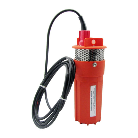
- Page 1 User Manual SUBMERGED PUMP ENGLISH...
-
Page 2: Table Of Contents
INTRODUCTION This manual has been provided as an aid to the operator with information about installing, operating, and servicing of the 2440 Series Submersible Pump. The SINGFLO engineers and technicians who designed and manufactured these pumps have developed these instructions from their experiences. -
Page 3: Pump Connections & Installation Instructions
I. PUMP CONNECTIONS & INSTALLATION INSTRUCTIONS WARNING: IMPROPER INSTALLATION WILL VOID WARRANTY. 1) Select proper jacketed cable size (Fig.1). MINIMUM MAXIMUM RECOMMENDED CABLE TYPE DIMENSION OF CABLE DIMENSION OF CABLE Note: DO NOT select cables with .5 8 I N .4 2 I N irregular shapes, rough or (1 4 .5 m m ) -
Page 4: Coupler And Discharge For Outlet
f) Insert the wire leads into Plug (Cable Adapter) connectors. Using a 5/64" Allen Wrench tighten the set screws (Fig. 6). ) Slide the Inner Cable Boot (Part B) over the plug until it is flush with the first step on the collar (Fig. 6). Wipe the grease from the surface of Inner Cable Boot and cable. -
Page 5: Safety Line
D R O U G H T W A T E R L E V E L SINGFLO 2440 S ERIES S U B M E R S IBLE P U M P Refer to "Helpful Hints"... -
Page 6: Parts List And Replacement Part Kits
ITEM DESCRIPTION QUANTITY CABLE [NOT INCLUDED] INNER CABLE BOOT OUTER CABLE BOOT PLUG (CABLE ADAPTER) [NOT SHOWN] SCREW (PLUG) [NOT SHOWN] SCREW (LIFT PLATE) LIFT PLATE OUTLET FITTING O-RING (OUTLET FITTING) O-RING (LIFT PLATE) RECEPTACLE (CABLE ADAPTER) SET SCREW (RECEPTACLE) SCREW (MOTOR) FILTER SCREEN UPPER HOUSING... -
Page 7: Submersible Pump Assembly Drawing
VIEW A W E I Lower Filter Lift Plate Cable Plug Valve Housing Motor Canister Screen O-Ring 24-135-00 24-136-00 24-137-00 24-138-00 24-139-00 24-140-00 24-141-00 24-142-00... -
Page 8: Before Requesting Service "Helpful Hints
BEFORE REQUESTING SERVICE "Helpful Hints" SYMPTOM PROBABLE CAUSE CORRECTION PUMP OPERATES but: 1) LOW VOLTAGE 1) CHECK POWER SUPPLY FOR PROPER VOLTAGE. NO FLOW or REFER TO TECHNICAL SPECIFICATIONS (Pg. 16). REDUCED FLOW 2) NO WATER AT PUMP 2) MAKE SURE THE PUMP IS INSTALLED BELOW THE LOWEST ANTICIPATED WATER LEVEL. -
Page 9: Pump Removal And Disassembly
II. PUMP REMOVAL AND DISASSEMBLY For servicing using Replacement Part Kits. Warning: Make sure all electrical power is off and the Hose (Pipe) is not under pressure. Warning: Canister maybe pressurized, disassemble the pump in proper order. Follow the manual directions carefully. Note: Keep all of the parts clean after disassembly. - Page 10 7) Slide off the Filter Screen (Part M) (Fig. 10). 8) Remove the Canister (Part U) (Fig. 10). a) Using a 3/16" Allen Wrench remove the screws (Part V) from 3 places. b) Place one hand on the Upper Housing and the other on the Canister. Twist and pull the Assembly apart. 9) Remove Upper Housing (Part N) and Motor (Part T) (Fig.
-
Page 11: Pump Re-Assembly
III. PUMP RE-ASSEMBLY Warning: The order of Assembly is important to ensure proper sealing. M O T O R LEA D W IR E S 1) Install the Upper Housing Large O-Rings (Part O) (Fig. 11). a) Remove the existing Large O-Rings and thoroughly clean the O-Ring grooves with a dry cloth and a cotton tipped applicator. - Page 12 6) Install the Canister (Part U) (Fig. 12). a) Clean the inside of the Canister with a dry cloth. b) Align the wire channel in the canister with the motor lead wires. c) Slide the canister over the entire assembly . d) Twist the canister to align the screw holes and carefully press on end to seat properly.
- Page 13 11) Install the Filter Screen (Part M) (Fig. 15). a) Slide the Filter Screen onto the Upper Housing (Part N). b) Align the slots in the Filter Screen with the screws (Part V) in the Upper Housing and slide the Filter Screen over the screws. 12) Install the Outlet Fitting (Part G) (Fig.
-
Page 14: Application Worksheet And Flow Charts
APPLICATION WORKSHEET Please fill in for your records. PUMP DISTRIBUTOR: MODEL NUMBER_____________________________ SERIAL NUMBER_____________________________ Name_______________________________________________ MFG. DATE__________________________________ Address_____________________________________________ PURCHASE DATE_____________________________ City________________________________________________ TOTAL WELL DEPTH_________________FT(M) Phone( )__________________________________________ WELL RECOVERY RATE________________________________________________________________________________________________________ SOLAR ARRAY INFORMATION: MAKE/MODEL_______________________________________________________________________________________________ WATTS AVAILABLE ______________________________________________________ (NO. OF PANELS X WATTS PER PANEL= ) CONTROLLER INFORMATION: MAKE/MODEL_______________________________________________________________________________________________ NOTE: Use of an LCB (Linear Current Booster) Unit is required for optimum performance. -
Page 15: Power Supply
TERMS: H1=DISCHARGE HEAD = Vertical distance in feet from ground level to level of water in elevated storage tank. H2=WATER LEVEL = Vertical distance in feet from level of water in well when pumping up to ground level. H3=SUBMERGENCE = Vertical distance in feet from level of water in well when pumping, to pump position in well. Note: DO NOT submerse the pump deeper than necessary unless the water level is known to be highly variable (Pump may operate dry for short periods of time.) -
Page 16: Technical Specifications
TECHNICAL SPECIFICATIONS: MODEL NUMBER: YM 2440-30 PUMP DESIGN: Positive Displacement 3 Chamber Diaphragm Pump CAM: 3.0 Degree MOTOR: Permanent Magnet, P/N 11-175-00 Thermally protected VOLTAGE: 24 VDC Nominal WATTS: 120W AMPS: 4.0 MAX FUSE: 7.5 AMP (Automotive) 3.75 in. (95 mm) INTERNAL BYPASS: 105-110 P.S.I. -
Page 17: Tools Required For Installation & Maintenance
TOOLS REQUIRED FOR INSTALLATION & MAINTENANCE *#1 and #2 Phillips Screwdriver Wire Cutters *5/64" Allen Wrench Wire Strippers *5/32" Allen Wrench Pliers *3/16" Allen Wrench Dry Cloth or Cotton Tipped Applicator for cleaning O-Ring grooves Electrical Tape Tie wraps *Note: A tool kit is available, components included are listed above. NOTES:____________________________________________________________________________________ ____________________________________________________________________________________________ ____________________________________________________________________________________________... -
Page 18: Warranty
LIMITED WARRANTY PROCEDURE warrants its pump to be free of defects in material and workmanship to the original retail SINGFLO purchaser for the period of one year beginning with the purchase date of the unit or, in the absence of proof of purchase date, one year from the date of manufacture as shown on the pump, not to exceed two (2) years in any event.
Need help?
Do you have a question about the 2440 Series and is the answer not in the manual?
Questions and answers