Table of Contents
Advertisement
Quick Links
Download this manual
See also:
Instruction Manual
JVC SERVICE & ENGINEERING COMPANY OF AMERICA
DIVISION OF JVC AMERICAS CORP.
Head office
:
1700 Valley Road Wayne, New Jersey 07470-9976
East Coast
:
10 New Maple Avenue Pine Brook, New Jersey 07058-9641
Midwest
:
705 Enterprise Street Aurora, Illinois 60504-8149
:
5665 Corporate Avenue Cypress, California 90630-0024
West Coast
:
1500 Lakes Parkway Lawrenceville, Georgia 30043-5857
Atlanta
:
2969 Mapunapuna Place Honolulu, Hawaii 96819-2040
Hawaii
JVC CANADA INC.
Head office
:
21 Finchdene Square Scarborough, Ontario M1X 1A7
:
Montreal
16800 Rte Trans-Canadienne, Kirkland, Quebec H9H 5G7
:
Vancouver
13040 Worster Court Richmond, B.C. V6V 2B3
(973)317-5000
(973)396-1000
(630)851-7855
(714)229-8011
(770)339-2582
(808)833-5828
(416)293-1311
(514)871-1311
(604)270-1311
S40895-04
Printed in Japan
SERVICE MANUAL
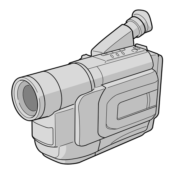
COMPACT VHS CAMCORDER
GR-AX770U/AX970U
SPECIFICATIONS
(The specifications shown pertain specifically to the model GR-AX770)
Camcorder
General
Format
: VHS NTSC standard
Power source
: DC 11 V
(Using AC Adapter)
DC 6 V
(Using battery pack)
Power consumption
Viewfinder on
: 3.7 W
Signal system
: NTSC-type
Video recording system
Luminance
: FM recording
Color
: Converted sub-carrier direct recording
Conforms to VHS standard
Cassette
:
cassette
Tape speed
SP
: 33.35 mm/sec. (1-5/16 ips)
EP
: 11.12 mm/sec. (7/16 ips)
Recording time (max.)
SP
: 40 minutes
EP
: 120 minutes
(with TC-40 cassette)
Operating
temperature
: 0°C to 40°C (32°F to 104°F)
Operating humidity : 35% to 80%
Storage temperature : –20°C to 50°C (–4°F to 122°F)
Weight
: Approx. 850 g (1.9 lbs)
Dimensions
: 200 mm x 112 mm x 115 mm
(W x H x D)
(7-7/8" x 4-7/16" x 4-9/16")
Pickup
: 1/4" format CCD
Lens
: F1.6, f = 3.9 mm to 62.4 mm,
16:1 power zoom lens with auto iris and macro control,
filter diameter 40.5 mm
Viewfinder
: Electronic viewfinder with 0.5" black/white CRT
White balance
adjustment
: Auto/Manual adjustment
This service manual is printed on 100% recycled paper.
COPYRIGHT © 2002 VICTOR COMPANY OF JAPAN, LTD.
Connectors
Video
: 1 V (p-p), 75 Ø unbalanced, analog output (via
Video output connector)
Audio
: 300 mV (rms), 1 kØ analog output
(via Audio output connector)
AC Adapter
Power requirement
U.S.A. and Canada : AC 120 V`, 60 Hz
Other countries
: AC 110 V to 240 V`, 50 Hz/60 Hz
Output
: DC 11 V
, 1 A
Optional Accessories
• Battery Packs BN-V12U, BN-V20U, BN-V400U
• A/V (Audio/Video) Cable
• Compact VHS (
) Cassettes TC-40/30/20
• Active Carrying Bag CB-V7U
Some accessories are not available in some areas. Please consult
your nearest JVC dealer for details on accessories and their
availability.
Specifications shown are for SP mode unless otherwise indicated.
E & O.E. Design and specifications subject to change without notice.
No. 86663
January 2002
Advertisement
Table of Contents

Subscribe to Our Youtube Channel
Related Manuals for JVC GR-AX770U


Summary of Contents for JVC GR-AX770U
- Page 1 (with TC-40 cassette) Some accessories are not available in some areas. Please consult JVC CANADA INC. Operating your nearest JVC dealer for details on accessories and their temperature : 0°C to 40°C (32°F to 104°F) availability. Operating humidity : 35% to 80% Storage temperature : –20°C to 50°C (–4°F to 122°F)
-
Page 2: Table Of Contents
3.2.1 Tilt ..................3-2 3.2.2 Centering ................. 3-2 3.2.3 Vertical scanning .............. 3-2 3.2.4 Brightness ............... 3-2 3.2.5 Focus ................3-2 The following table lists the differing points between Models GR-AX770U and GR-AX970U in this serise. GR-AX770U GR-AX970U E.VF COLOR... -
Page 3: Important Safety Precautions
Important Safety Precautions Prior to shipment from the factory, JVC products are strictly inspected to conform with the recognized product safety and electrical codes of the countries in which they are to be sold. However, in order to maintain such compliance, it is equally important to implement the following precautions when a set is being serviced. - Page 4 • Safety Check after Servicing Examine the area surrounding the repaired location for damage or deterioration. Observe that screws, parts and wires have been returned to original positions, Afterwards, perform the following tests and confirm the specified values in order to verify compliance with safety standards.
-
Page 5: Disassembly
SECTION 1 DISASSEMBLY 1.1 SERVICE CAUTIONS 1.1.3 Connection of the wires 1.1.1 Precautions Pull both ends of the connector in the arrow direction, re- move the lock and disconnect the flat wire. 1. Before disassembling/re-assembling the set as well as soldering parts, make sure to disconnect the power ca- ble. -
Page 6: Tools Required For Adjustments
1.2 TOOLS REQUIRED FOR ADJUSTMENTS Alignment tape Alignment tape Service support system PC cable (for SP interchangeability) (for N. SP PB Y/C level) YTU94057-56 QAM0099-002 MHP-C MHV-2C Cleaning cloth Torque driver YTU94088 KSMM-01 YTU94088-003 Conn. ring INF adjustment lens Table 1-2-1 YTU92001-111 YTU92001B Gray Scale Chart... -
Page 7: Disassembly/Assembly Of Cabinet Parts
1,2. Alignment tape 1.3 DISASSEMBLY/ASSEMBLY OF CABINET PARTS To be used for check and adjustment of interchange- 1.3.1 Disassembly flow chart ability of the mechanism. This flowchart indicates the disassembly step for the cabi- (Video: Color bar signal, Audio: Non-signal) net parts and board assembly in order to gain access to item(s) to be serviced. -
Page 8: Disassembly Method
1.3.2 Disassembly method REMOVAL STEP *UNLOCK/RELEASE/ Fig. /LOC PART UNPLUG/UNCLAMP/ UNSOLDER CASETTE COVER (S1), 3(L1a), (L1b), (L1c), ASSEMBLY Push button, Spring (L1c) UPPER CASE 2(S2), 2(L2) LOWER CASE 9(S3), (L3a), (L3b), CN3a, ASSEMBLY COVER(JACK) (Incl. E.VF ASSEMBLY) E.VF ASSEMBLY 3(S4) TOP OPERATION 2(S5),(L5a),(L5b),2(L5c), UNIT... - Page 9 COVER (JACK) Fig. C3 (L5c) (S5) (S5) (L5a) (L5b) CN5a Fig. C4 Fig. C5...
- Page 10 (L6b) (S6) (S6) CN6a (L6a) (S6) Fig. C6 (S7a) (L7a) For DC LIGHT MODEL ONLY (S7a) (L7c) (S7a) CN7a (L7c) (S7b) (L7b) Fig. C7...
- Page 11 (S8a) (S8a) (S8b) : 0.098N·m (1.0kgf·cm) Fig. C8 (S9) (S9) : 0.098N·m (1.0kgf·cm) Fig. C9...
-
Page 12: Disassembly/Assembly Of Camera Section And Deck Section
1.4 DISASSEMBLY/ASSEMBLY OF CAMERA SECTION Reference Notes: AND DECK SECTION <NOTE 1> Destination of connectors 1.4.1 Flowchart of disassembly Note : Two kinds of double-arrows in connection tables The following flowchart shows the disassembly of the cam- respectively show kinds of connector/wires. era section and deck section. - Page 13 SHIELD CASE (MAIN) ∗ ∗ ∗ : 0.108 N m (1.1 kgf • • Fig. D2 Fig. D4 ∗ ∗ ∗ ∗ CUSHION (OP) ∗ : 0.216 N m (2.2 kgf • • Fig. D3 Fig. D5...
-
Page 14: Replacement Of 3 Ccd Image Sensor
1.5 REPLACEMENT OF 3 CCD IMAGE SENSOR Part Name Orientation Notes: CCD image sensor Mark is on the right viewed as indi- cated by the arrow a . • Pay the most careful attention to the transparent glass and optical LPF of the CCD image sensor so a not the soil and Spacer rubber IC side is horizontal. -
Page 15: Take Out Cassette Tape
1.6 TAKE OUT CASSETTE TAPE In the event that the set enters the emergency mode as it 5. For taking in the slack of the tape, run the mechanism is loaded with a cassette tape and the cassette tape can- to the EJECT position as the front lid of the cassette is not be ejected with the EJECT button, manually, take it out left open, and turn the take-up gear in the forward di-... -
Page 16: Emergency Display
1.7 EMERGENCY DISPLAY Example (in case of the error number E01): Whenever some abnormal signal is input to the mechacon CPU, an error number (E01, as an exam-ple) is displayed in the electronic view finder. In every error status, such the message as shown below al- UNIT IN REMOVE AND ternately appear over and over. - Page 17 Note: 2) As the “DEMO MODE” is executed, the camcoder enters the DEMONSTRATION mode after the ti- tle screen of “TITLE CALL” and “FUTURE” appear in this order. <Flow chart> 1. TITLE CALL and FUTURE ∫ 2. EASY PC CONNECTION ∫...
-
Page 18: Service Note
1.9 SERVICE NOTE 1-14... -
Page 19: Mechanism Adjustment
SECTION 2 MECHANISM ADJUSTMENT 2.1 SERVICE CAUTIONS 2.1.3 Required adjustment tools 2.1.1 Precautions Alignment tape Alignment tape 1. Before disassembling/re-assembling the set as well as MHP-LC MHP-C soldering parts, make sure to disconnect the power ca- ble. 2. When disconnecting/connecting connectors, pay enough attention to wiring not to damage it. -
Page 20: Disassembly/Assembly Of Mechanism Parts
2.2 DISASSEMBLY/ASSEMBLY OF MECHANISM PARTS This procedure starts with the condition that the cabinet parts and deck parts. Also, all the following procedures for adjust- ment and parts replacement should be performed in STOP mode. When reassembling, perform the step(s) in the reverse order. - Page 21 <TOP VIEW> Fig. 2-2-1 TOP VIEW <BOTTOM VIEW> Note: When reinstalling the cassette housing to the set, pay careful attention to the switch not to damage it. Fig. 2-2-2 BOTTOM VIEW...
- Page 22 (W1a) (S3a) (W3b) (S3b) (P3) (P1) (W3a) (S1) (W3a) (W1a) (W3a) (W1a) (W1b) (S3a) (S3a) (S3a) (S3a) Fig. M1 Fig. M3 (W2) (S4a) (S4b) (W4) (W2) (S4b) (S2) (W2) Fig. M2 Fig. M4...
- Page 23 (S5a) (S5a) (S7) (S5a) (S5c) (S5b) Fig. M5 Fig. M7 (S6b) (S8) (S8) Catcher (S6d) (W8a) (S6d) (S6d) (S6d) (W8b) (W8b) (S6c) (S6c) (S6a) Fig. M6 Fig. M8...
-
Page 24: Checkup And Adjustment Of Mechanism Phase
2.3 CHECKUP AND ADJUSTMENT OF MECHANISM PHASE Note: Pay careful attention to the installing order and phase of mechanism parts of the loading system. Align the two holes of the Loading ring assembly to those of the deck. Align the hole of the Loading gear (T) assembly to that of the deck. -
Page 25: Tape Transport Adjustment
2.4 TAPE TRANSPORT ADJUSTMENT 8. When the FM waveform breaks in the level varying proc- ess, subtly adjust the height of guide rollers at every In most cases the deck section is in need electrical ad- breaking point so that the waveform varies as flat as pos- justment, it results from replacement of worm mechanical sible. -
Page 26: A/C Head Height & Azimuth
11. Through the above steps, confirm that there occur no 2.4.3 A/C head height & azimuth wrinkling and damage in the tape around the pinch roller 1. Connect the jig connector cable to CN25 on the MAIN and TU guide pole whenever the deck is in operation of board. -
Page 27: Phase Of Control Head (X Value)
2.4.4 Phase of control head (X value) 2.5 REMARKS 1. Connect the jig connector cable to CN25 on the MAIN 2.5.1 Cleaning board. 1. For cleaning of the upper drum (particularly video 2. Playback the SP stairstep signal of the alignment tape heads), use fine-woven cotton cloth or Kimwipe with al- and observe signal at V.TP FM with external trigger from cohol soaks through. -
Page 28: Jig Connector Cable Connection
2.6 JIG CONNECTOR CABLE CONNECTION Remove the cover (JIG). Jig connector cable CN25 Cover(JIG) Extention connector For supplying the power through the coupler by removing NOTE: the cover (for jig), use this extension connector double for connecting the jig connector cable. JIG CONNECTOR COMMUNICATION CABLE to 10 pin... -
Page 29: Electrical Adjustment
2 PROM onto new board. Then adjustment are not required. And if parts such as the following need replacement, spe- cial computerized adjustment are required (Refer to “5. Con- (LY20701) nection for Service support system”.). Please contact to JVC Service for detaile information. Serial No. label Bottom case assy •... -
Page 30: Electronic Viewfinder (E. Vf) Adjustment
3.2 ELECTRONIC VIEWFINDER (E. VF) ADJUSTMENT 1) Put the deflection yoke to the most inner side of CRT [B/W VF model only] neck first. Then fix the stopper temporary. 2) Adjust the tilt of picture on the E. VF screen by tilting Notes: the deflection yoke.
Need help?
Do you have a question about the GR-AX770U and is the answer not in the manual?
Questions and answers