Table of Contents
Advertisement
Quick Links
Advertisement
Table of Contents

Summary of Contents for Squirrel Systems Squirrel Workstation 8
- Page 1 Squirrel Workstation 8 SQ-2020 Operator and Service Manual Revision 1.0...
- Page 2 Information in this document is subject to change without notice. No part of this document may be reproduced or transmitted in any form or by any means, electronic or mechanical, for any purpose, without the express written permission of Squirrel Systems. © 2003 Squirrel Systems. All rights reserved.
- Page 3 Squirrel Workstation 8 Records of Revision Date Reference: Revision Comments Check Page, Paragraph, Approval Drawing No. Mar 31/05 Rev 1.0 Initial Release D. O’Brien...
-
Page 4: Table Of Contents
TABLE OF CONTENTS TABLE OF CONTENTS CHAPTER 1: GENERAL INFORMATION........1-1 INTRODUCTION .................... 1-1 SPECIFICATIONS ..................1-2 ACCESSORIES ..................... 1-4 WORKSTATION 8 DIMENSIONS ..............1-5 PRODUCT DESCRIPTION ................1-7 CHAPTER 2: DISASSEMBLY and ASSEMBLY......2-1 General Servicing Precautions..............2-1 Service Equipment and Parts List .............. 2-1 Removing the Front Cover ................. - Page 5 TABLE OF CONTENTS PROPER INSTALLATION OF MOUNTING HARDWARE ......3-3 Tilt Stand (92-205) Installation ..............3-3 Adjusting the Tilt Stand ................3-6 Mounting the Workstation 8 to a Wall Bracket (92-207) ......3-8 Wall Mount ..................3-8 Counter Sunk Mount ................. 3-9 HOST/SERVER COMMUNICATION PROTOCOL ........
- Page 6 TABLE OF CONTENTS APPENDIX E: TOUCHSCREEN SENSOR ..........6-10 Cleaning ....................6-10 Specifications ................... 6-10 APPENDIX F: MOTHERBOARD PREPARATION ........6-12 Foil Taping the Rear Shield Casing (89-541)........... 6-13 Foil Tape Specifications ................6-14 APPENDIX G: .................... 6-15 Connector Descriptions ................6-15 Jumper Descriptions.................
-
Page 7: Chapter 1: General Information
GENERAL INFORMATION CHAPTER 1: GENERAL INFORMATION The General Information Chapter includes three sections: • Introduction • Specifications • Accessories • Product Dimensions • Product Description INTRODUCTION This publication is intended to provide technical support information for Squirrel systems installers, field service technicians and depot service technicians. Information in this manual includes: •... -
Page 8: Specifications
GENERAL INFORMATION SPECIFICATIONS Standard SBC PROCESSOR Intel Celeron 850 MHz or Pentium 3 up to 1GHz Functions - Socket 370 BIOS Standard Award® PC 256 KB Flash BIOS Includes ETHERNET LINUX boot SYSTEM CHIPSET VIA VT82C694/VT82C686 On-board 512KB SECOND LEVEL OF CACHE two 168 - pin DIMM sockets (supports up to 512MB SDRAM) One parallel port (LPT2) - Page 9 GENERAL INFORMATION CHIPSET C & T 69000 Flat Panel / PCI - 2 MB integrated memory SVGA Interface: 2 MB on-board memory DISPLAY MEMORY DISPLAY TYPE 12.1” Color TFT – Hi Brightness LCD Resolution: 800x600 Touchscreen 5 Wire 12.1” ELO-Touch Analogue OVERLAY Resistive overlay Interface...
-
Page 10: Accessories
GENERAL INFORMATION Mechanical and OPERATING TEMPERATURE 50° to 105.8° F (10° to 40° C) Environmental OPERATING HUMIDITY 5% to 95% relative humidity 12.47 lbs (5.64 kg) WS on stand WEIGHT 7.10 lbs (3.22 kg) WS only ACCESSORIES Standard ETHERNET CABLE CHECK PRINTER COMMUNICATION Standard CABLE... -
Page 11: Workstation 8 Dimensions
GENERAL INFORMATION WORKSTATION 8 DIMENSIONS 3/24/05 Preliminary Release... - Page 12 GENERAL INFORMATION Side Dimensions External Power Supply Dimensions Preliminary Release 3/24/05...
-
Page 13: Product Description
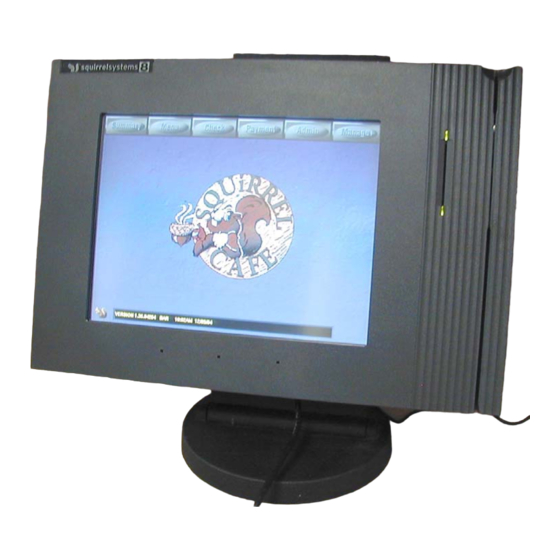
GENERAL INFORMATION Product Description Touchscreen Optical ID Reader Badge Card Slot Air Exhaust Magswipe Area Reader/Slot Adjustable Stand and Backplate Power Switch Keyboard Port Internal Intake Fan Vents 3/24/05 Preliminary Release... - Page 14 GENERAL INFORMATION 6 5 4 3 1. Power Jack – AC/DC Power Supply Adaptor is connected here. 2. Ethernet Port – 10/100 Base – T/TX, RJ45 Jack for SquirrelOne Network Connection. 3. COM 4 – RJ12 Interface Jack configured for default Customer Display Tower.
-
Page 15: Chapter 2: Disassembly And Assembly
DISASSEMBLY AND ASSEMBLY CHAPTER 2: DISASSEMBLY AND ASSEMBLY General Servicing Precautions The following are general precautions that should be taken by technicians when servicing the Workstation 8 product. Please refer to APPENDICES at the back of the manual for a detailed explanation. •... - Page 16 DISASSEMBLY AND ASSEMBLY Reassembly Instructions Reassembling is the reverse of the disassembly process. Use care to ensure that all cables and screws are returned to their proper positions. Check that no loose parts have been left inside and everything is properly installed and tightened.
- Page 17 DISASSEMBLY AND ASSEMBLY Various cables, screws and miscellaneous parts Part Description Part Number Cable RJ12 to RJ12 Interface SQ-7035 Use: COM1 COM2 COM4 Cable CATS Ethernet Patch SQ-7706 Use: SquirrelOne Cable RJ12 to RJ45 Printer Interface SQ-7345 Use: COM2 Cable Cash Drawer SQ-7175 Use: DRW Dual Cash Drawer Adaptor...
- Page 18 DISASSEMBLY AND ASSEMBLY Power Switch 74-020 Power Switch Cable 76-338 Plastic Card Guide 99-608 Black Cable Tie 86-015 91-070 ISIS Cable 76-301 Adjustable Stand with Weight Assy 92-205 Base 92-195 Back Plate 99-604 Wall Mount Bracket 92-207 Rear Workstation 8 Plastic Housing 99-618 Top Workstation 8 Plastic Cover 99-622...
-
Page 19: Removing The
DISASSEMBLY AND ASSEMBLY Removing the Front To remove the Front Cover: Cover This procedure requires a #2 Phillips screwdriver. 1. Place the WORKSTATION 8’s front of the unit face down on the anti-static mat. Ensure that the mat is clean of debris that could scratch or damage the workstation. - Page 20 DISASSEMBLY AND ASSEMBLY Front/Top Cover Front/Top Cover Front View Back View Spray coated with copper loaded paint for EMI/RFI shielding Optical ID Reader (Isis Badge Reader) Magswipe Reader Power Switch Base Bottom Housing Sensor/Overlay LCD Mounting Bracket 2-6 Preliminary Release 3/24/05...
-
Page 21: Replacing The
DISASSEMBLY AND ASSEMBLY Replacing the Front Cover Front/Top Plastic Cover 10.25” RF Gasket Strip (2 pcs) (99-622) (88-053-1) Touch strip (on front side) Badge Card Slot (99-623) Magswipe Card Slot 7.35” RF Gasket Strip (2 pcs) (88-053-2) Backside View In the event the top cover is damaged and is required to be replaced, it should be noted that the top cover consists of the following: Top cover plastic, RF Gasket Strips and the Touch Strip located in front of the cover. -
Page 22: Removing The Isis Badge Reader (Optical Reader)
DISASSEMBLY AND ASSEMBLY Red Wire 1. Remove Screw ISIS Detector PCB Magswipe Reader ISIS Emitter PCB Interface Cable 2. Disconnect Removing the ISIS 1. Without touching the emitter (emitting diode) and detector Badge Reader (phototransistor) components (these will either be gold or (Optical Reader) silver), carefully grasp the top edges of the emitter and detector boards and gently slide them (together) upwards... - Page 23 DISASSEMBLY AND ASSEMBLY Removing the ISIS Reader 2. Both the detector & emitter boards need to be disconnected from the ribbon cable. Always handle these boards by holding their edges and avoiding touching the components and circuitry. The ribbon cable can only be disconnected from the Motherboard after the LCD Mounting Bracket is disassembled from the Internal Shield Housing.
- Page 24 DISASSEMBLY AND ASSEMBLY 3. Ensure that each green LED on the ISIS Badge Reader PCBs are properly aligned with the card guide lightpipes as shown below. The LED should not touch the card guide but should be about 1/16” (1 mm) away. ISIS Card Guide/Lightpipe...
-
Page 25: Removing The 'Dg41 Lcd Assembly (Mounting Bracket) From The Rear Internal Shield Assembly
DISASSEMBLY AND ASSEMBLY Removing the ‘DG41 The ‘DG41 LCD Panel requires an Open Frame Inverter LCD Assembly (DMA23058) which is mounted to the backside of the LCD (Mounting Bracket) Mounting Bracket. NO T E from the Rear Internal Shield Assembly The LCD Mounting Bracket is merely resting on top (acting as a lid) of the Rear Internal Shield Assembly. - Page 26 DISASSEMBLY AND ASSEMBLY 2. Disconnect the Touchscreen Sensor Cable, Backlight Cable and LCD Data Cable from the Motherboard and lift the LCD Mounting Bracket clear away from the Rear Internal Shield Assembly. Backlight Cable Touchscreen Sensor Cable LCD Data Cable After the LCD Mounting Bracket has been completely removed, the ISIS cable can now be disconnected from the Motherboard.
-
Page 27: Disassembly Of The 'Dg41 Lcd Assembly
DISASSEMBLY AND ASSEMBLY Make sure the Touch-screen cable tail is positioned properly in between the notch of the rear metal casing before resting the LCD Mounting Bracket on top of the casing. The Touch-screen cable tail NO T E should also be bent with a radius as it is channeled through the notch and should move freely through the notch. -
Page 28: Reassembling/Replacing The Touch Screen Sensor (Overlay)
DISASSEMBLY AND ASSEMBLY Reassembling/Replacing the Touch Screen Sensor (Overlay) Before mounting the Touchscreen Sensor, the face of the LCD display must be clean of any dust or debris. Refer to APPENDIX B LCD Handling. The backside of the Touchscreen Sensor must also be cleaned of any fingerprints. Refer to APPENDIX E Touchscreen Sensor. - Page 29 DISASSEMBLY AND ASSEMBLY 3. Cut cable tie securing backlight cable 5. Cut the cable tie that is securing the 4. Disconnect the LCD Data Cable Backlight Cable 6. Carefully pull back the RF Gasket (do not completely remove). 7. Carefully turn the LCD Mounting Bracket over, right side up. Be careful not to touch the LCD’s display surface when turning the LCD Mounting Bracket over.
-
Page 30: Disconnecting The Lcd Data Cable
DISASSEMBLY AND ASSEMBLY Disconnecting the LCD Data Cable When disconnecting the LCD data cable from the LCD connector, attention should be paid to how the data cable is oriented and connected to the LCD NO T E connector. Removing the Open Frame Inverter Turn the LCD Mounting Bracket over. -
Page 31: Reassembly
DISASSEMBLY AND ASSEMBLY Reassembly Reassembly is almost the opposite process of disassembly. 1. Make sure the LCD Data Cable is connected in the proper orientation to the LCD and Torque Seal has been applied to either side of the data cable connector. -
Page 32: Base Bottom Disassembly
DISASSEMBLY AND ASSEMBLY 5. Adjust and position the LCD, then tighten the screws using a crisscross pattern. DO NOT USE POWER TOOLS, ONLY HAND TIGHTEN THE MOUNTING SCREWS. Binding Torque Value: 0.196N x m (2.0Kgf x cm) NO T E 6. -
Page 33: Disassembly Of The Internal Shield Assembly
DISASSEMBLY AND ASSEMBLY Reassembly Reassembly is the reverse of the disassembly process. Disassembly of the Internal Shield Assembly Removing the Internal Shield Assembly out of the Base Bottom Plastics 1. The Internal Shield Assembly sits inside the Base Bottom Plastic Housing and is not secured to the Bottom Plastic Housing in any way. -
Page 34: Removing The Intake Fan
DISASSEMBLY AND ASSEMBLY 2. Gently push the switch through the Base Bottom Housing until the switch pops out. Reassembly Reassembly is the reverse of the disassembly process. Removing the Intake Fan 1. Disconnect the fan’s 3-pin connector plug from the 3-pin header (Reference Designator: CN2) on the motherboard. -
Page 35: Removing The Motherboard From The Internal Shield Housing
DISASSEMBLY AND ASSEMBLY Reassembly Reassembly is the reverse of the disassembly process. Make sure the cable tail from the fan is of the correct length. If not then any excess cable needs to be bunched neatly together and cable tied to achieve the proper cable length. -
Page 36: Resetting Cmos For Squirrel Defaults
DISASSEMBLY AND ASSEMBLY Reassembly Reassembly of the same motherboard in the Shield Housing is the reverse of the disassembly process. 1. Inserting the motherboard into the Rear Shield Housing should be done with care and without any stress to the board. 2. -
Page 37: Removing The Card Guide Rails
DISASSEMBLY AND ASSEMBLY Turn power on or re-boot system and press the “DEL” key on the keyboard to access CMOS. When the CMOS main menu appears select “Load Optimized Defaults” to load Squirrel’s Default Settings. Save settings and exit CMOS for changes to take effect. Removing the Card Guide Rails •... -
Page 38: Chapter 3: Installation
INSTALLATION CHAPTER 3: INSTALLATION Installation of the SQUIRREL WORKSTATION 8 involves the following recommendations: • General guidelines • Electrical Power Requirements • Location and mounting positions • Proper installation of the mounting hardware • Host/Server Communication Protocol • ISIS Badge Reader Configuration •... - Page 39 INSTALLATION 8. Workstation should be kept away from high heat sources such as grills, fryers and heat lamps. 9. Location should have adequate space for the external power supply; check printer and cash drawer installation. The external power supply must have 1" clearance on all sides. Electrical Power Requirements The power line for the Workstation 8 must be kept in accordance with the SQUIRREL POWER SPECIFICATION GUIDE.
-
Page 40: Tilt Stand (92-205) Installation
INSTALLATION ANGLED WALL MOUNT SIDE WALL MOUNT “TRADITIONAL” COUNTER SUNK FLUSH WALL MOUNT COUNTER TOP (Using Wall Bracket) (Using Wall Bracket) Proper Installation of the Mounting Hardware Tilt Stand (92-205) Installation The Tilt Stand can be used to suspend the Workstation 8 from a shelf, rack, wall, or to support the Workstation on a countertop in a traditional fashion. - Page 41 INSTALLATION Tilt Stand Back Plate Figure 3-1. WORKSTATION 8 with Tilt Stand Similarly, the Workstation 8 can be secured to the Back Plate sideways except when attached from the left. Use only two screws as shown in Figure 3-2. Tilt Stand Back Plate Figure 3-2.Workstation 8 with Tilt Stand (Sideways from Left) 3-4 Preliminary Release...
- Page 42 INSTALLATION For counter top mounting where the Tilt Stand is not to be screwed to the countertop, a weight can be attached to the base of the Tilt Stand as shown in Figure 3-3. The base weight is shipped standard with the Workstation 8. Figure 3-3.
-
Page 43: Adjusting The Tilt Stand
INSTALLATION Adjusting the Tilt Stand To adjust the angle of the Tilt Stand: 1. Remove the three base screws that secure the stand to the wall, countertop or shelf if necessary. See Figure 3-5. The Workstation may have to be removed in order to do this. BASE SCREWS BASE... - Page 44 INSTALLATION Set Screws (3) (1/8” Allen key) Figure 3-6. Tilt Stand Base Setscrews. 3. Using a 1/8" Allen Key, loosen these screws just enough so that the back-plate of the stand begins to move. While holding the stand against the mounting surface, adjust the back-plate to the angle desired.
-
Page 45: Mounting The Workstation 8 To A Wall Bracket (92-207)
INSTALLATION Mounting the Workstation 8 to a Wall Bracket (92-207) The Wall Bracket can be used in two ways: to attach the Workstation to a wall, or to provide a slight tilt for a flush counter- mount installation. WALL MOUNT Mounting screws MUST be secured into the wall stud. -
Page 46: Counter Sunk Mount
INSTALLATION COUNTER SUNK MOUNT The Wall Bracket can be attached to the back of the Workstation to provide a slight tilt when the unit is mounted on a counter top. The four mounting screws used to secure the Workstation 8 to the Tilt Stand can be used to attach the Wall Bracket to the Workstation as shown in Figure 3-8. -
Page 47: Isis Badge Reader Configuration
INSTALLATION ISIS Badge Reader Configuration The ISIS badge reader can be configured for the type of ISIS Badge Card series used. Series 1 was the original badge type. Series 2 was developed to extend the range of ID numbers. See STN 073 for more detailed information. - Page 48 INSTALLATION Multi I/O Connector Label The color scheme on the Cable Location Label developed for earlier Squirrel Workstation models for each port/connector descriptor still holds for the WS8 product. This color scheme was introduced to aid in connecting peripherals to their respective I/O port connectors.
-
Page 49: Typical Workstation & Peripheral Setup
INSTALLATION Typical Workstation & Peripheral Setup Matching Color Band SQ-7706 SQ-7035 SQ-7035 SQ-7035 SQ-7175 Power Supply Note: depending on peripheral, COM port can be configured to support Ethernet Patch Cable the following: Printer Tower Weigh Scale Cash Drawer Bar Code Reader Printer Tower Weigh Scale... -
Page 50: Final Testing Of The Installation
INSTALLATION All interface cables EXCEPT the Power Supply connection can be made while the Workstation is powered on. Hence any communication cables can be replaced without powering down the Workstation. Final Testing of the Installation Once the power, ethernet and peripherals have been interfaced to Powering It On the Workstation, it is now ready to be powered on. -
Page 51: Screen Contrast
INSTALLATION 5. Once POS is loaded onto the Workstation and the Workstation has initialized, insert a badge card into the Badge Reader to configure the reader for the type of badge series to be used. Screen Contrast The Workstation 8 is designed so that the screen contrast is preset to the maximum setting and thus eliminating the need for contrast control. -
Page 52: Chapter 4: Maintenance
MAINTENANCE CHAPTER 4: MAINTENANCE There is relatively little general maintenance for the SQUIRREL WORKSTATION 8, but disregarding maintenance will result in long term problems for the user. Caring for the WORKSTATION 8 The WORKSTATION 8 and its associated cables and peripherals should not be immersed in liquids. -
Page 53: Cleaning The Credit Card Reader
MAINTENANCE Cleaning the Credit Card Reader Regular use of the Credit Card Reader results in a residue buildup on the magnetic head within the reader. This degrades performance and will lead to the eventual failure of the credit card reader. Regular cleaning of the reader will prevent this problem from occurring. -
Page 54: Chapter 5: Troubleshooting
TROUBLESHOOTING CHAPTER 5: TROUBLESHOOTING If the WORKSTATION 8 is required to be serviced on site (restaurant), it is advisable that the service technician bring along a fully functional Workstation in the event that the Workstation in question requires more than a simple service. - Page 55 TROUBLESHOOTING Problem Possible Solutions Badge Reader will not read Badge Check that the Badge Reader function Cards. is enabled in the POS software. Refer to the software manual on Top LED of the Badge Reader Badge Reader setup. is either continuously flashing or off.
- Page 56 TROUBLESHOOTING Problem Possible Solutions Check that the ISIS LED goes off for a short period while a M/R card is being swiped. Does this happen? If not, check that the Mag Reader’s cable is connected/seated properly to the right angle connector located at the back of the ISIS Detector boards.
- Page 57 TROUBLESHOOTING Problem Possible Solutions Swap in a known working printer and if the problem still persists then the problem lies with the Workstation. Problem could be component related on the Motherboard. Cash Drawer will not open. The Squirrel Diagnostic feature available in the SquirrelOne software can be used in conjunction with a Squirrel Cash Drawer Tester (SQ-...
- Page 58 TROUBLESHOOTING Problem Possible Solutions Inverter board component level failure. LCD screen unreadable; Character Check that the LCD data cable is missing pixels; Screen abnormal; seated properly at the LCD and Wrong color displayed; Horizontal or Motherboard end. vertical lines displayed. Damaged or defective LCD data NOTE: a few pixel abnormalities may cable.
-
Page 59: Chapter 6: Appendices
APPENDICES CHAPTER 6: APPENDICES APPENDIX A ESD Work-station Work-station Components 4. Floor Mat 5. Floor Mat 6. ESD Awareness Sign 3. Wrist Strap A walking surface that A sign that provides A two-part device Ground Cord dissipates static A cable and warning text and symbol including a wristband charge from... -
Page 60: Maximum Allowable Resistances And Discharge Times For Static Safe
APPENDICES APPENDIX A Maximum Allowable Resistances and Discharge Times for Static Safe Operations Reading from Operator Maximum Tolerable* Maximum Acceptable through: Resistance Discharge Time Floor mat to ground 1000 megohms Less than 1 sec. Table mat to ground 1000 megohms Less than 1 sec. -
Page 61: Prime Sources Of Static Electricity In An Electronics Work Area
APPENDICES APPENDIX A Prime Sources of Static Electricity in an Electronics Work Area 1. People: Walking, rocking in a chair, getting up from a chair, putting on or removing work smocks - any brisk or repetitive motion. 2. Clothing: Clean room smocks, synthetic shirts, sweaters, pants etc. Shoes with synthetic (such as neoprene, foam rubber) soles and heels. -
Page 62: Field Service - Esd Prevention
APPENDICES APPENDIX A Field Service – ESD Prevention Field service technicians are required to take appropriate steps to make sure they are properly grounded before handling any circuit boards. If a field service technician is at a site and is not equipped with a portable ESD field service kit, the technician must keep NO T E in mind that touching a metal chassis whether grounded or not will only temporarily bring the technician to the same potential as the chassis. -
Page 63: Appendix Blcd Handling
APPENDICES APPENDIX B LCD Handling ESD Protection • LCD’s are very susceptible to electrostatic discharge failure and so extra care should be exercised when handling these devices. When working with an LCD, be sure to ground your body and any electrical equipment you may be using. •... -
Page 64: Cleaning
APPENDICES APPENDIX B LCD Handling Do not disassemble or modify the LCD module as this can cause permanent damage and should be strictly avoided. Any non-authorized modifications, ampering or physical damage will void the manufacturer’s warranty. The cold cathode fluorescent lamp in the LCD panel contains a small amount of mercury. -
Page 65: Ingestion And Injury Warning
APPENDICES APPENDIX B LCD Handling Ingestion and Injury Warning LCD is composed of glass, liquid crystal, spacer dust and many other chemicals. Should the display break, caution must be taken to avoid contact with liquid crystal. When there is case of skin contact, wash immediately with soap & water and make sure that there are no glass chips remaining on the skin. -
Page 66: Appendix C Handling Circuit Boards
APPENDICES APPENDIX C Handling Circuit Boards Measures should be taken to ensure that technicians are properly grounded before handling the Motherboard (SBC) or any other circuit boards. Certain components on the Motherboard are sensitive to static electricity and can be damaged by discharge. •... -
Page 67: Appendix D: Port Signal Pin Assignment
APPENDICES APPENDIX D Port Signal Pin Assignment COM1 COM2 DRW COM3 COM 1 DRW (Drawer) RS-232 Signals Pin1 = Gnd Pin1 = Gnd Pin3 = STATUS C/D Pin2 = TXD Pin4 = C/D1 Pin3 = CTS (default) or RXD Pin5 = Gnd Note: Pin3 is internally configurable Pin6 = C/D2 Pin4 = RXD... -
Page 68: Appendix E Touchscreen Sensor
APPENDICES APPENDIX E Touchscreen Sensor Active Area Border Cable Cleaning Clean the active surface (resistive surface) of the touchscreen with Isopropyl 99% and lint free wipes. Always dampen the wipes and then clean the touchscreen. The backside of the touchscreen can be cleaned with a household glass cleaner (Windex) to remove any fingerprints. - Page 69 APPENDICES APPENDIX E Touchscreen Sensor Expected Life The AccuTouch technology has been operationally tested to more than 35 million touches in one location without failure using a stylus similar to a finger. Environmental Temperature Operating: -10°C to 50°C. Storage: -40°C to 71°C. Relative Humidity Based on 24-hour period, non-condensing.
-
Page 70: Appendix F: Motherboard Preparation
APPENDICES APPENDIX F MOTHERBOARD PREPARATION PCI1 Note - CN8: The clip on the Keyboard Connector must be present. CN17 POD-6706 REV.A1 CN22 CN10 CN11 CN23 CN13 CN14 CN15 CN21 CN24 CN16 CN12 CN18 CN19 CN17 CN20 CN25 CN26 Parts not populated to make room for chassis fan: CN11 –... - Page 71 APPENDICES APPENDIX F FOIL TAPING THE REAR SHEILD CASING (89-541) FOR EMI PURPOSES 1 ½” x ¾” METAL FOIL TAPE (88- 1 ½” x ¾” METAL FOIL TAPE (88- 025) TO THE OUTSIDE CORNERS 025) TO THE OUTSIDE CORNERS OF THE SHIELD CASING. OF THE SHIELD CASING.
-
Page 72: Foil Tape Specifications
APPENDICES APPENDIX F Foil Tape Specifications Description: 3M 1183 EMI Tin-Plated Copper Foil Shielding Tape o Smooth tin-plated copper foil with a conductive acrylic pressure-sensitive adhesive on liner. o Its acrylic adhesive has good resistance to heat, oxidation, solvents and oils. Properties Typical Values Backing thickness... -
Page 73: Connector Descriptions
APPENDICES APPENDIX G Connector Descriptions CN1 - CPU FAN PWR DIMM1 & DIMM2 – DIMM SOCKETS CN6 - FLOPPY PWR JP1 - ISIS J6 – TOUCHSCREEN SENSOR CN7 – INVERTER/BACK LIGHT PWR (TFT DISPLAY) JP2 - KYBRD CN22 – KYBRD + MS CN8 –... -
Page 74: Jumper Descriptions
APPENDICES APPENDIX G Jumper Descriptions J5 (NEXT TO BATTERY) CLEAR RTC FRONT PANE TOUCHSCREEN RESET J1 - FAN PWR WATCHDOG ADDRESS SELECT ISIS RESET BACKLIGHT SELECT BACKLIGHT BACKLIGHT J9 - LCD TYPE SELECT WATCHDOG J22 – COM1 RI/PWR SEL JP6 – COM1 RS-485/422 J12 –... -
Page 75: Jumper Settings Information
APPENDICES JUMPER SETTINGS INFORMATION APPENDIX G BACKLIGHT BACKLIGHT SELECT – J3 SELECT – J21 TOUCHSCREEN FAN PWR – J1 RESET – J2 Default Default Default Default Factory Setting Factory Setting Factory Setting Factory Setting FRONT PANE – J4 BACKLIGHT CLEAR RTC – J5 ISIS RESET –... - Page 76 APPENDICES APPENDIX G JUMPER SETTINGS INFORMATION COM1 (RS232) for POS Printer – CN24, JP6, J27, J22, JP4, J15 CN24 J22 – Configures PWR/GND to CN24 Pin 8 2 4 6 8 10 1 2 3 2 4 6 1 3 5 7 9 Jumper Position 1 3 5 Default...
- Page 77 APPENDICES APPENDIX G JUMPER SETTINGS INFORMATION COM2 (RS232) for POS Printer – CN25, JP7, JP9, J25, J23, JP3, J17 CN25 2 4 6 8 10 1 2 3 1 2 3 1 3 5 7 9 Default Default Default Default Factory Setting Factory Setting Factory Setting...
- Page 78 APPENDICES APPENDIX G JUMPER SETTINGS INFORMATION COM4 (RS232) for Tower – J16, J18, J24, JP8, JP5 2 4 6 1 3 5 Default Default Factory Setting Factory Setting Default Factory Setting 2 4 6 8 10 12 14 16 18 1 2 3 1 3 5 7 9 11 13 15 17 Default...
-
Page 79: Appendix H: Butterfly Shield Screw
APPENDICES APPENDIX H Butterfly Shield Screw When installing SQUIRREL equipment such as the Wall Bracket and the Tilt Stand to a fragile wall surface such as gyproc, "Butterfly Shield" type screws should be used. Regular screws may easily pull out of the wall causing the equipment to fall and damaging the wall's exterior finish. -
Page 80: Appendix I: Lcd Bracket Preparation For Mounting The Lq121S1Dg41 Display
APPENDICES APPENDIX I LCD BRACKET PREPARATION FOR MOUNTING THE LQ121S1DG41 DISPLAY REAR VIEW STEP 1 Note: When placing the RF Gaskets, there should be no gap in between the end of the INSTALL RF GASKET STRIPS AROUND RF Gasket strip and the start of the next RF PERIMETER OF BRACKET.
Need help?
Do you have a question about the Squirrel Workstation 8 and is the answer not in the manual?
Questions and answers