Table of Contents
Advertisement
Operating & Maintaining the
Connex500/350 3-D Printer
Starting the Connex Printer ............................................................... 2
Loading Model and Support Cartridges.......................................... 4
Producing Models ............................................................................... 5
Resuming Production After Printing has Stopped......................... 9
Changing the Model Material ......................................................... 10
Keeping the Connex Printer in Idle Mode..................................... 15
Shutting Down the Connex Printer ................................................ 16
Maintaining the Connex Printer ..................................................... 18
DOC-13000 Rev. E
Printer Interface Color Key.................................................................. 7
Printing Indicators ................................................................................ 8
Routine Maintenance Schedule......................................................... 18
Cleaning the Print Heads ................................................................... 19
Pattern Test........................................................................................... 21
Improving Print Quality .................................................................... 22
Cleaning and Replacing the Wiper................................................... 23
Replacing the Roller Scraper (Knife) ................................................ 28
Aligning the Print Heads ................................................................... 30
Calibrating Print Heads ..................................................................... 34
Replacing Print Heads........................................................................ 40
Testing and Calibrating the UV Lamps ........................................... 49
Calibrating the Load Cells ................................................................. 51
Replacing the Odor Filter................................................................... 52
Replacing the UV Lamps ................................................................... 52
Built-in Tests......................................................................................... 57
Replacing the Waste Container ......................................................... 62
Cleaning the Exterior Panels ............................................................. 64
7-1
Advertisement
Table of Contents

Summary of Contents for Connex Connex500
-
Page 1: Table Of Contents
Operating & Maintaining the Connex500/350 3-D Printer Starting the Connex Printer ............... 2 Loading Model and Support Cartridges.......... 4 Producing Models ................5 Printer Interface Color Key..............7 Printing Indicators ................8 Resuming Production After Printing has Stopped......9 Changing the Model Material ............10 Keeping the Connex Printer in Idle Mode........15 Shutting Down the Connex Printer ..........16 Maintaining the Connex Printer ............. 18 Routine Maintenance Schedule............18 Cleaning the Print Heads ..............19 Pattern Test................... 21 Improving Print Quality .............. -
Page 2: Starting The Connex Printer
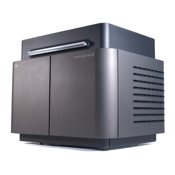
Figure 7-1: The Connex500 3-D Printer Starting the Connex Printer CAUTION! • Do not attempt to operate the Connex printer before being trained by an Objet customer-support representative. • Observe all safety warnings and follow the safety guidelines described in chapter 2. - Page 3 Stop button Pause button Figure 7-3: Connex500 interface Connex installations utilize one monitor for displaying both the computer running Objet Studio / Job Manager and the computer installed inside the printer. Make sure that the KVM (keyboard-video-mouse) switch is in the correct position so that the Connex printer interface is displayed.
-
Page 4: Loading Model And Support Cartridges
Operating & Maintaining the Connex500/350 3-D Printer Loading Model and Support Cartridges Connex printers use two cartridges of model material and two cartridges of support material, each weighing 3.6 kilograms when full. A graphical representation of the cartridges and their current weight appears in the printer interface (see figure 7‐3). —— The printer uses RFID technology to automatically identify the material cartridges. For this purpose, an RFID module is part of the printer hardware. -
Page 5: Producing Models
• The print block is heated. • The UV lamps are powered and they warm up. When printing begins, Job Manager sends seven slices to the Connex printer. This is the standard buffer between the Job Manager and the printer. As each slice is printed, the Job Manager sends another slice to the printer. Depending on the size of the model(s) to be produced, printing can take between several hours to several days. As long as there is enough model and support material in the supply cartridges, printing proceeds automatically until the job is finished. During printing, the server computer must remain on and it must communicate with the Connex printer. Do not log-off Windows until printing is finished. 7–5 DOC-13000 Rev. E... - Page 6 Operating & Maintaining the Connex500/350 3-D Printer The Connex500/350 printer uses one or two model‐material cartridges and one support‐material cartridge to produce models. If additional cartridges are installed and they are not needed for the current print job, the printer interface indicates which are being used: • Blue cartridge—used for the print job • Gray cartridge—not used for the print job You can monitor printer status indicators by switching the printer interface display. To do this, click the display toggle button in the printer interface screen. Block temp. Block temp. behind behind model support heads heads Temp. of each Temp. of each model head support head Block temp. in Block temp.
-
Page 7: Printer Interface Color Key
Connex500/350 User Guide Printer The background colors in the printer indicator fields tell you at a glance Interface whether or not the value or item is suitable or ready for printing. Color Key • Green—suitable/ready for printing For example, in figure 7‐4: Ambient—The ambient temperature of the printing chamber is within the acceptable range. Heads Liquid—The level of model and support material in the print‐ block reservoir is OK. Heads Vacuum—The vacuum level in the system is within the acceptable range. • Red—not suitable for printing (or indicates a warning) For example, in figure 7‐4: Waste—The weight of the waste container is grams, more than allowed when beginning a print job. (See “Replacing the Waste Container” on page 7‐62.) • Blue—not ready For example, in figure 7‐4: UV lamps—The UV not on. Heads (°C)—The heads have not reached the temperature required for printing models (in printing mode). The color of the material cartridges displayed in the printer interface indicates which cartridges are active for the current (or next) print job. • Blue—active cartridges • Gray—reserve cartridges 7–7... -
Page 8: Printing Indicators
Operating & Maintaining the Connex500/350 3-D Printer Printing The printer interface screen changes when you send a print job from Job Indicators Manager to the printer, and the printer is on line (see figure 7‐5): • The mode changes from Pre‐print to Printing. • The specific activity being performed is shown in the “current activity” field. • Current job‐printing information is displayed. • The printing progress bar is displayed. • The Stop and Pause buttons are enabled. When the weight of a cartridge drops below 100 grams, the display of the material level in the printer interface is red. Printer mode Current Activity Job information Job information Progress bar Stop button Pause button Figure 7-5: Connex printer interface during printing 7–8... -
Page 9: Resuming Production After Printing Has Stopped
2. Make sure that the computer network connecting the printer and Job Manager server is active. 3. In the Job Manager interface, click the Resume icon 4. In the Continue from Slice dialog box that appears, confirm the slice number, after checking the Connex printer interface. Printer mode Last slice printed Figure 7-6: Connex printer interface after interrupted printing Figure 7-7: Continue from Slice confirmation dialog box in server (Job Manager) interface 5. If, for any reason, the correct number does not appear in the dialog box, enter the number and click You cannot continue printing the model if: • The number of the last slice printed does not appear in the Connex ... -
Page 10: Changing The Model Material
1. Cancel the print job in Job Manager. 2. Remove the partially printed model from the build tray. 3. Send the job to the Connex printer again. You can stop and later resume printing from either the Connex printer interface or the Job Manager interface, since both applications are updated when you use these commands. However, after clicking the Pause button in the printer interface, you can only resume printing from the printer interface. - Page 11 Connex500/350 User Guide 4. In the Compartment Selection screen, select the cartridge(s) you want to replace, and click Next Figure 7-9: Compartment Selection screen 5. From the drop‐down menu, choose the model material you want to install, and click Next Figure 7-10: Material Selection screen Note: This selection automatically affects the default material settings in Objet Studio. 6. The Material Replacement Wizard continues as follows: • If, according to your selections in the previous wizard screens, you are replacing both model material cartridges, and the printer will be loaded with two cartridges containing the same model material, the Connex printer flushes the entire system, and prepares for printing ...
- Page 12 Operating & Maintaining the Connex500/350 3-D Printer printer will be loaded with cartridges containing two different model materials, the Printer Mode Selection screen appears. Figure 7-11: Printer-mode selection 7. Choose whether you want to produce models in Single‐Material mode or in Digital‐Material mode, and click . Next • Single Material mode All four print heads are used to print, using one model material. This mode is required to produce build trays with the High Quality setting, and to produce trays with the High Speed setting using only one model material. • Digital Material mode Each of the model materials loaded is used in two of the four print heads. If only one of the model materials is required for printing, models are produced using two print heads. This makes it unnecessary to replace the other model material cartridge. If model‐material substitution is allowed, the printer produces trays with the High Speed setting using a mixture of both model materials (see “Model Material Substitution” on page 5‐37). Continue with step 8 on page 13.
- Page 13 Connex500/350 User Guide 8. In the Flushing Options screen (see figure 7‐12), choose how thoroughly you want to flush the system. Figure 7-12: Flushing Options screen • Economy. This cycle can be used when replacing a light‐colored model material with a darker material (such as TangoBlack™ or VeroBlack™), or if the exact color of the printed models is unimportant. The wizard flushes the system with the minimum amount of material needed to ensure that models have the mechanical properties of the new material. • Efficiency. This option is adequate, in almost all situations, for printing models with uniform and accurate color. It is recommended because it can potentially save 25 to 75 percent of the material used to flush out the old material, compared to the High Performance cycle. Note, however, that there may be times when the shade (color) of the printed model is slightly affected by material previously used. The wizard identifies the feed tubes and print heads requiring cleaning, based on your selections in the previous screens, and flushes only these parts of the system. • High Performance. Use this cycle when the printed models must have the exact color of the new material. The wizard thoroughly flushes all of the feed tubes and print heads needed for printing, based on your selections in the previous screens. This is done even if a selected material is already present in the system, since it might contain small amounts of material previously used. 7–13...
- Page 14 Figure 7-13: Material Replacement warning screen Once you start this procedure, you must complete it before you can produce models with the Connex printer. To perform the procedure at another time, click Cancel. If you continue (by clicking Next) and you do not complete the procedure, you must start the Material Replacement wizard again before producing models.
-
Page 15: Keeping The Connex Printer In Idle Mode
To put the printer into Idle mode: From the File menu (in the printer interface) click Exit Note: The printer remains in Idle mode until you open the Connex printer application and begin printing again. When the printer is in Idle mode, do not turn it off. It can remain in this mode—with the cover closed—for up to a week. -
Page 16: Shutting Down The Connex Printer
Operating & Maintaining the Connex500/350 3-D Printer Shutting Down the Connex Printer You only need to shut down the Connex printer if it will not be used for a week or more. Otherwise, the printer can remain on, in Idle mode. To properly shut down, the printer needs to perform several processes. These are controlled by the Shutdown wizard. Do not attempt to shut down the printer by simply closing the computer interface (the printer‐control application), and never disconnect power to the printer before completing this wizard. Depending on the length of time the printer will not be used, you can choose between a short shutdown procedure, and a more thorough procedure. • Up to 10 days: The wizard empties the print block of model and support material, to prevent leaks. This takes about 10 minutes. • More than 10 days: The wizard empties the print block, then flushes the system with cleaning fluid. This takes up to 35 minutes, and you must be present to load cleaning‐fluid cartridges when instructed. To run the Connex Shutdown Wizard: 1. Select from the Options menu, or press Shutdown Figure 7-16: Shutdown wizard, opening dialog box 2. - Page 17 Connex500/350 User Guide The shutdown procedure begins. Figure 7-17: Shutdown progress screen 5. When the final wizard screen appears, close the printer‐control application and shut down the built‐in computer. Figure 7-18: Final Shutdown Wizard screen 6. After the printer computer shuts down, turn off the main power switch (at the back of the printer) (see figure 7‐2 on page 2). 7–17 DOC-13000 Rev. E...
-
Page 18: Maintaining The Connex Printer
Operating & Maintaining the Connex500/350 3-D Printer Maintaining the Connex Printer The performance of routine maintenance tasks is essential for getting satisfactory results from Connex 3‐D printers. Perform the tasks at specified intervals for optimum performance. Routine Maintenance Frequency Task For More Information Schedule Daily, before printing Clean the print heads. See “Cleaning the Print Heads” on page 7‐19. Weekly Clean the build tray and the surrounding area. Weekly Perform the Pattern test. See “Pattern Test” on page 7‐21. Weekly Clean and inspect the See “Cleaning and wiper. -
Page 19: Cleaning The Print Heads
Connex500/350 User Guide Cleaning the Periodic inspection and cleaning of the orifice plates on the bottom of the Print Heads print block ensures that the print nozzles are not clogged. A wizard guides you through the procedure, and adjusts components of the Connex printer to enable you to perform it. This procedure takes about 20 minutes, and should be done at the beginning of the work day or before a big printing job. To clean the print heads: 1. Prepare— • isopropanol (IPA—isopropyl alcohol) or ethanol (ethyl alcohol) • disposable cleaning gloves • an Objet‐supplied cleaning cloth or equivalent • a mirror 2. Start the Heads Cleaning wizard from the Options menu of the printer interface (see figure 7‐26 on page 23). 3. Follow the instructions on the wizard screens, and select the check boxes to confirm that: • you have checked that the tray is empty. • you have closed the cover. - Page 20 Operating & Maintaining the Connex500/350 3-D Printer 5. When the following screen appears, open the cover. Figure 7-20: Head cleaning wizard—steps 5–10 WARNING: The print head orifice plates (bottom surface) may be hot. Do not touch them with your bare hands, and proceed with caution. 6. Place the mirror on the build tray.
-
Page 21: Pattern Test
Connex500/350 User Guide 11. Remove the cleaning materials from the printer and close the cover. 12. Select the confirmation check boxes in the wizard screen and click Next The head‐purge cycle begins. When this is complete, the final wizard screen appears. Figure 7-22: Head cleaning wizard—final screen 13. Click to close the wizard. Done Pattern Test The pattern test is the basic verification of the printer’s ability to produce quality models, since it demonstrates the condition of the nozzles in the print heads. Make sure, therefore, that you perform this test weekly, and whenever you suspect a printing problem. To perform the pattern test: 1. Make sure that the build tray is empty. 2. Prepare a sheet of pink paper—A‐4 or Letter size. 3. In the Connex printer, tape the pink paper to the surface left of the build tray. 4. Press ... -
Page 22: Improving Print Quality
Operating & Maintaining the Connex500/350 3-D Printer Figure 7-25: Sample Pattern Test 6. Carefully inspect the test paper to see if there are missing lines. Too many missing lines, especially if they are in the same area, indicates that the quality of printing when producing models will be poor. If this is the case, see “Improving Print Quality,” below. Note: Acceptable model quality is subjective, and depends on the type and scale (size) of the models produced. As a rule, however, more than 10 missing lines in one area of a column is considered unacceptable. -
Page 23: Cleaning And Replacing The Wiper
Connex500/350 User Guide Cleaning and A rubber wiper removes excess material from the print heads after the Replacing the purge sequence. This is done automatically before each print job, and Wiper performed manually during maintenance tasks. You should clean the wiper and surrounding area at least once a week. If the wiper is damaged or worn, replace it. To inspect and clean the wiper: 1. Prepare— • isopropanol (IPA—isopropyl alcohol) or ethanol (ethyl alcohol) • disposable cleaning gloves • an Objet‐supplied cleaning cloth or equivalent • a spare wiper 2. Start the Wiper Cleaning wizard from the Options menu of the printer interface. Figure 7-26: Starting the Wiper Cleaning wizard 3. Close the printer cover, and click ... - Page 24 Operating & Maintaining the Connex500/350 3-D Printer Confirm this in the wizard screen. Figure 7-27: Wiper Cleaning procedure—step 4 5. Click . Next 6. When the following screen appears, open the cover. Figure 7-28: Wiper Cleaning wizard during steps 7–10 7. Put on the cleaning gloves. 8. Using a generous amount of cleaning fluid and the cleaning cloth, remove any material remaining on the wiper and the surrounding area. 9. Inspect the wiper. If the wiper is scratched, torn or worn, or if you cannot clean it completely, replace it. a. Grasp it and pull it up and out of its bracket. ...
- Page 25 Connex500/350 User Guide 12. Select the confirmation check boxes in the wizard screen and click Next Figure 7-29: Wiper Cleaning procedure—final confirmation screen 13. Click to close the wizard. Done Cleaning the The roller waste collector removes waste material scraped from the roller. Roller Waste Suction removes this waste to the printer’s waste container. Collector and This assembly should be cleaned weekly to prevent a blockage in the tubes Inspecting the leading to the waste container, so that waste material does not overflow Roller Scraper into the printer. (Knife) To clean the roller waste collector: 1. Prepare—...
- Page 26 Operating & Maintaining the Connex500/350 3-D Printer 3. Remove the right UV‐lamp assembly: a. Disconnect the UV power cable and the fan power cable. Fan power connector Power connector Screw Figure 7-30: Disconnecting the right UV assembly b. Remove the screw attaching the right UV lamp to the print block, and then pull and lift up the UV lamp. 4. Loosen the two screws securing the suction tube on the print block Suction tube screws Figure 7-31: Lifting the suction tube 5. Lift the suction tube to secure it in a raised position.
- Page 27 Connex500/350 User Guide Roller waste collector screws Figure 7-32: Removing the roller waste collector covering 7. Remove the covering by pulling it out, and then lower it. 8. Clean the roller waste collector and the scraper blade surface using cotton swabs. Make sure to remove any remaining printing materials. Figure 7-33: Cleaning the roller waste collector Before replacing the covering you can check the effectiveness of the roller scraper (knife)—see below.
-
Page 28: Replacing The Roller Scraper (Knife)
Operating & Maintaining the Connex500/350 3-D Printer 7. Return the roller waste collector to the print block and screw on the covering (see figure 7‐32 on page 7‐27). 8. Loosen the screws securing the suction tube. Figure 7-35: Suction tube correctly positioned 9. Lower it so that the hole in the panel behind the suction tube is visible, and tighten the screws to secure the suction tube. 10. Attach the right‐UV‐lamp assembly to the print block and reconnect the UV power and fan cables. Replacing the You should replace the roller scraper blade: Roller Scraper • after 1,000 hours of printing. (Knife) • if it does not effectively keep the roller clean. You should periodically test the effectiveness of the roller scraper when you clean the roller waste collector. - Page 29 Connex500/350 User Guide 4. Remove the screws that secure the roller scraper assembly. Figure 7-37: Removing the roller scraper screws Figure 7-38: Removing the old roller scraper blade 5. Remove the scraper blade and discard it. 6. Place the new scraper blade onto the pins in the holder, as shown. Figure 7-39: Inserting the new roller scraper blade 7–29 DOC-13000 Rev. E...
-
Page 30: Aligning The Print Heads
Operating & Maintaining the Connex500/350 3-D Printer 7. Insert and tighten the roller scraper blade screws. Important: • Tighten the screws in the order shown in Figure 7-40. • Use the new screws supplied in the replacement-kit. Figure 7-40: Tightening the roller scraper screws 8. After tightening the screws, inspect the blade and make sure that it is straight. If necessary, loosen the screws and tighten them again, evenly. - Page 31 Connex500/350 User Guide 5. When instructed to do so, place the transparency on the build tray— next to the left and rear edges of the tray, as shown in the following figure. Figure 7-41: Positioning the transparency on the build tray 6. Make sure that the transparency sheet is lying flat, and tape it to the tray. 7. In the wizard screen, select the check box to confirm that the transparency sheet is on the build tray, and click Next The Connex printer prints the head alignment test on the transparency. 8. When the following screen appears, remove the transparency. Figure 7-42: Head Alignment wizard—steps 8–10 7–31 DOC-13000 Rev. E...
- Page 32 Operating & Maintaining the Connex500/350 3-D Printer The transparency sheet is printed with sets of vertical lines in seven columns, each showing the results from a different print head. Figure 7-43: Sample head-alignment test • The three columns on the right were printed by the heads used for applying model material when producing models. From right to left, the columns represent heads M1, M2, M3, respectively. (There is no column for head M0 because its alignment is used as a reference for aligning all other heads.) • The four columns of lines on the left were printed by the heads used for applying support material. The columns represent heads S3, S2, S1 and S0, respectively. 9. For each column of lines, use a magnifying glass or loupe to inspect pairs of consecutive rows printed on the transparency to see where the vertical lines align. Alignment-line numbering, left-to-right Row pairs Figure 7-44: Comparing rows of alignment lines Note: It does not matter which pair of lines you inspect, since they were all printed by the same head.
- Page 33 Connex500/350 User Guide The first in a series of alignment screens appears. Figure 7-45: Head alignment screen 11. In the head‐alignment screen, select the number that indicates which lines align in the upper and lower rows of a pair on the transparency (counting from the left) for this print head. Note: Because the alignment of the fourth lines is optimum, the number “4” is selected, by default, in the wizard screen. This does not change the head alignment.
-
Page 34: Calibrating Print Heads
Operating & Maintaining the Connex500/350 3-D Printer 14. In the final wizard screen, choose to either repeat the head alignment procedure or close the wizard. • If the most closely aligned vertical lines for a print head were at either extreme—the first or seventh lines—choose Yes to run the head‐alignment wizard again, then click . Next The transparency test will show if the heads are now properly aligned, and—if not—the wizard will allow you to “fine tune” the alignment. • If the vertical lines for the print heads were not aligned at either extreme, choose No to close the wizard, then click Next Figure 7-47: Final wizard screen Calibrating The condition of the print heads directly affects the quality of printed Print Heads models. To maintain optimum printing, you should routinely test the print heads, and calibrate them to the best working configuration possible. You do this by running the Head Optimization wizard. During the optimization process, 32 samples are printed on the build tray. After carefully weighing each of them, you enter the weight in the wizardʹs data‐entry screen. The wizard uses this data to optimize the heads. If, during the optimization process, the wizard determines that a print head is faulty—or that it is negatively affecting layer uniformity with the current ... - Page 35 Connex500/350 User Guide 2. Start the Head Optimization wizard from the Options menu of the printer interface. Figure 7-48: Starting the Head Optimization wizard 3. In the opening wizard screen, click to begin. Next The Wizard Conditions screen appears. 4. Read the conditions, select I Agree and click Next 5. Close the printer cover, and confirm this in the wizard screen. 6. In the following screen, make sure Optimize all print heads is selected, and click Next Figure 7-49: Procedure selection screen The print block moves into position for cleaning and inspecting the print heads. 7–35 DOC-13000 Rev. E...
- Page 36 Operating & Maintaining the Connex500/350 3-D Printer 7. When the following screen appears, clean the print heads. WARNING: The print head orifice plates (bottom surface) may be hot. Do not touch them with your bare hands, and proceed with caution. Figure 7-50: Clean print heads screen 8. Place the mirror on the build tray.
- Page 37 Connex500/350 User Guide The head‐purge cycle runs, after which the Weight Test is printed. Figure 7-52: Printing Weight Test 15. 32 samples are printed on the build tray, four for each of the print heads. This can take up to 55 minutes. 16. When the following screen appears, open the printer cover. Enter the data that describes the condition of each print head, after inspecting each of the printed samples. Figure 7-53: Weight Test Data Entry screen The layout of the data entry screen matches the printed samples on the build tray. Enter the data for the sample indicated by in the screen.
- Page 38 Operating & Maintaining the Connex500/350 3-D Printer Ruler Missing line Printed sample Figure 7-54: Measuring the missing line in a printed sample In the example above, you would enter “1” in the wizard screen. b. Carefully remove the sample, weigh it, and enter the weight in the wizard screen. Be sure to remove and weigh the entire sample, even if it breaks into several pieces. c. Click Apply or press Enter. The data‐entry‐indicator moves to the next position. d. Repeat these steps for all 32 samples. To change an entry, click Edit Data, enter the correct data, and click Save.
- Page 39 Connex500/350 User Guide However, if the wizard determines that a print head is faulty—or that it is negatively affecting model quality with the current head configuration—the wizard instructs you to replace it. In this case, the following screen appears. Figure 7-56: Defective print heads found 18. Choose Replace defective head(s) if you are prepared to replace the print heads now. or— Choose Abort wizard if you want to replace the print heads at another time. Replacing print heads is expensive. Replace them only after consulting with an Objet-authorized customer-support engineer. If you are replacing the print heads now, the wizard guides you through the procedure when you click . Continue with “Preparing the print block” Next on page 41.
-
Page 40: Replacing Print Heads
Operating & Maintaining the Connex500/350 3-D Printer Replacing The condition of the print heads directly affects the quality of printed Print Heads models. You need to replace a print head if one or more of the following symptoms occurs: • The Head Optimization wizard determines that one or more print heads are defective. (See “Calibrating Print Heads” on page 34.) • There are noticeable grooves in the surface of printed models. • Visual inspection of the head reveals that its surface is damaged— peeling or bubbles in the nozzle area. • The Connex interface displays a warning or malfunction message relating to a print head— Head Heater temperature timeout Head Heater thermistor open Head Heater thermistor short Replacing print heads is expensive. Replace them only after consulting with an Objet-authorized customer-support engineer. - Page 41 Connex500/350 User Guide The Wizard Conditions screen appears. 4. Read the conditions, select I Agree and click Next Figure 7-57: Procedure selection screen 5. Choose Replace faulty heads, and click Next 6. Select the print head(s) needing replacement, and click Preparing the Next print block Figure 7-58: Head selection screen The Connex printer heats and empties the print block, and prepares the printer. (This should take up to 30 minutes.) Figure 7-59: Printer preparation progress screen 7. Put on the safety gloves. 7–41 DOC-13000 Rev. E...
- Page 42 Operating & Maintaining the Connex500/350 3-D Printer 8. When the following screen is displayed, open the Connex printer cover. Note: The Connex printer disconnects power to the heads for your safety. Figure 7-60: Replace the defective head when this screen appears Removing the 9. On the print block, release the upper and lower screws that secure the print head in the block. (If necessary, you may use a screwdriver to Defective Head loosen the screws.) Figure 7-61: Releasing the locking screws 10.
- Page 43 Connex500/350 User Guide 11. Loosen the screws on the door of the compartment protecting the print‐head driver cards (A), then pull and lift up the door (B). Figure 7-63: Opening the print-head compartment 12. Pull the print‐head driver card out of its socket so that the head is free (A), and remove it from the bottom of the print block (B). Figure 7-64: Releasing the print-head driver card to remove the head 13. Make sure that along with the head, you remove the two rubber O‐ring seals. Figure 7-65: O-ring seals on the print head Important: If the seals are not removed with the head, they are probably stuck to the print block housing.
- Page 44 Operating & Maintaining the Connex500/350 3-D Printer Figure 7-66: Making sure the O-rings are not stuck to the print block Important: Remove the protective tape from the surface of the Installing the New Head new print head. 14. Inspect the replacement head, and make sure that the O‐ring seals are in place (see figure 7‐65). 15. Gently insert the replacement head into the vacant slot in the print block, and push the print‐head driver card into its socket. Note: Make sure to insert the head with the driver card facing its socket, in the rear of the print block.
- Page 45 Connex500/350 User Guide 16. Push the head up until you hear it click into place, in both front and rear holders. Figure 7-68: Clicking the head into place in the print block 17. Lower the door of the print head compartment, and tighten the screws to lock it in place. 18. Tighten the upper and lower screws that secure the print head in the print block (see figure 7‐61 on page 42). Note: Hand-tighten these screws. Do not use a screwdriver. 19. With your fingers, make sure that the new head is level and even with the other heads. Figure 7-69: Checking the level of the new head 20.
- Page 46 Operating & Maintaining the Connex500/350 3-D Printer Figure 7-70: Installation-check screen 21. In the next wizard screen, select the check box to confirm that you have removed all tools and objects from the printer. Figure 7-71: Cleared-tray confirmation screen 22. Close the printer cover. The wizard continues by filling the heads, then heating and purging them. If there are no installation problems, the Head Optimization procedure begins (see “Calibrating Print Heads” on page 7‐34). If a vacuum leakage is detected, or if there are other problems, the wizard alerts you and instructs you how to continue (see “Installation Problems,” below). After replacing print heads, you should check the head alignment before using the Connex printer to produce models. In the final wizard screen... • select and click to open the Head Alignment wizard (see Done “Aligning the Print Heads” on page 30). • select and click ...
- Page 47 Connex500/350 User Guide Figure 7-72: Final Head Optimization Wizard Screen Installation If the printer detects that there is a problem after you install print heads, relevant warning screens appear. Problems • If the printer software does not sense the replaced head, the following warning screen appears. Figure 7-73: Incorrect-installation screen If this happens: a. Open the print head compartment (see figure 7‐63 on page 43). b. Re‐insert the print‐head driver card into its socket (see figure 7‐67 on page 44). c. In the wizard screen, select the check box to confirm that you have re‐inserted the card, and click Next 7–47 DOC-13000 Rev. E...
- Page 48 Operating & Maintaining the Connex500/350 3-D Printer • If the replacement head was not factory‐calibrated, the following warning screen appears. Figure 7-74: Invalid-data warning screen If this happens: a. Remove the head and replace it with another one (starting with step 9 on page 7‐42). b. In the wizard screen, select the check box to confirm that you have installed another print head, and click Next c. Contact your authorized Objet Customer Support center about the unformatted head. • If the vacuum test is not successful, the replacement head was not sealed properly during installation, and the following warning screen appears. Figure 7-75: Vacuum Leakage warning screen If this happens: a. Click ...
-
Page 49: Testing And Calibrating The Uv Lamps
Connex500/350 User Guide Testing and The effective radiation of the UV lamps used for curing models can change Calibrating the over time. To ensure optimum curing of models during printing, a pop‐up UV Lamps message reminds you to test the lamps and calibrate their effective UV radiation after every 200 hours of printing. You do this by running the UV Calibration Wizard and using the built‐in UV radiation sensor. The wizard compares the radiation you measure to the recommended radiation level for each of the lamps, at each printing mode—High Speed, High Quality and Digital Material. The radiation level is considered acceptable if it is within seven percent of the recommended level. When calibrating the lamps, the wizard attempts to adjust the radiation level, if necessary, and then prompts you to take a new reading. If the level is acceptable, the wizard continues to the next phase. If further adjustment is necessary, the current phase is repeated. If the level is too low to be adjusted, the wizard continues to the next phase; the final wizard screen indicates that the lamp’s radiation for the printing mode is unacceptable. To test and calibrate UV lamp radiation: 1. Start the UV Calibration wizard from the Options menu (see figure 7‐26 on page 23). 2. Make sure that the build tray is empty, the UV sensor is exposed and clean, and that the printer cover is closed. Confirm this in the wizard screen and click ... - Page 50 Operating & Maintaining the Connex500/350 3-D Printer When all test have finished, the results are displayed. This shows the current condition of the lamps, after the wizard has calibrated them. Figure 7-77: Results and current condition of the UV lamps 3. Cover the UV sensor, and confirm this in the next screen. 4. In the final wizard screen, click Done Figure 7-78: Final UV Calibration Wizard screen 7–50 DOC-13000 Rev. E...
-
Page 51: Calibrating The Load Cells
Connex500/350 User Guide Calibrating the Load cells are sensors that measure the weight of the printing cartridges Load Cells and the waste container in the printer. It is important that you periodically check that the weight measurements are accurate, both for convenience and to prevent unnecessary waste of printing materials. It is recommended that you calibrate the load cells once a month, with the Load Cell Calibration wizard. To calibrate load cells: 1. Start the Load Cell Calibration wizard. • From the Options menu of the printer interface (see figure 7‐26 on page 23), select Wizards > Load Cell Calibration 2. Select one or more load cells that you want to calibrate, and click Next Figure 7-79: Load cell selection Note: It is recommended that you routinely calibrate all of the load cells. -
Page 52: Replacing The Odor Filter
Operating & Maintaining the Connex500/350 3-D Printer 4. In the next wizard screen, observe the numbers and wait until the level is relatively stable—two units above or below the average level shown. Figure 7-81: Load cell calibration screen 5. Select the Weight is stable check box, and click Next If you need to calibrate more than one load cell, the next calibration screen appears. Repeat steps 4 and 5 until all of the load cells are calibrated. 6. Click in the final wizard screen. Done Figure 7-82: Final wizard screen Replacing the The Connex500/350 printer has an activated‐carbon filter for removing Odor Filter odors from printing materials. The filter should be replaced regularly (about once a year, as necessary) to keep your working environment pleasant. This is normally done during the yearly preventive‐maintenance service visit. ... - Page 53 Connex500/350 User Guide adjust their effective power with the UV Calibration Wizard (see “Testing and Calibrating the UV Lamps” on page 49. If you need to replace a UV lamp, follow these instructions: 1. Make sure the Connex printer is in offline mode. Figure 7-83: Offline mode indicator (red) The online/offline button at the bottom of the printer interface should be red. If not, click it to switch the printer to offline mode. WARNING: Before continuing, make sure that the safety interlock in the printer cover is not defeated, and that the lamp is not hot.
- Page 54 Operating & Maintaining the Connex500/350 3-D Printer 5. Disconnect the power connection to the UV lamp. Figure 7-86: Disconnecting the UV lamp Note: Do not disconnect the power connection to the cooling fans. 6. Loosen the screw securing the UV lamp cover , and pull the cover up , then out Figure 7-87: Removing the UV lamp cover 7. Pull the lamp reflector out of the print block.
- Page 55 Connex500/350 User Guide 8. Inspect the new lamp reflector, and make sure that a black strip is attached to the inside of it. If not, install one—on the side of the reflector opposite (not next to) the print block. Note: Extra black strips are included in the printer Start-up Kit. If necessary, you can remove the black strip from the old reflector and install it in the new reflector (as long as the black paint has not faded).
- Page 56 Operating & Maintaining the Connex500/350 3-D Printer 12. Reconnect the power connection to the UV lamp. Figure 7-91: Connecting power to the UV lamp 13. In the wizard screen, confirm that you have replaced the lamp(s) and that the black strip is attached, then click Next Figure 7-92: UV-installation confirmation screen The wizard operates the lamps and checks if their power is within the acceptable range for each printing mode. (The mode currently being checked appears in the lower‐left corner of the printer interface.) Figure 7-93: Status screen during UV lamp check 7–56 DOC-13000 Rev. E...
-
Page 57: Built-In Tests
Connex500/350 User Guide 14. After replacing a UV lamp, it is recommended that you calibrate its power for the various printing modes. The final screen allows you to continue to the UV Calibration wizard (see “Testing and Calibrating the UV Lamps” on page 7‐49). Figure 7-94: Final wizard screen Built-in Tests The software that runs your Connex printer contains a suite of tests for regularly checking the hardware and software, and for troubleshooting. You can configure basic communications and environment tests to run automatically, when the Connex software opens. In addition, you can run a more comprehensive set of tests before processing a print job, as a system check, to ensure optimum printing results. Because running the tests effects the operation of the printer, you can only open the Built‐in Tests interface when the Connex system is not printing. The test suite features: • The organization of printing‐related tasks in categories: Communications Data cards Temperatures Voltages Encoder repeatability Print‐head heating Print‐head filling • A clear display of test results and the source of any failures, enabling you to determine if printing is possible or worthwhile. • The ability to monitor test results for specific components. •... - Page 58 Operating & Maintaining the Connex500/350 3-D Printer Accessing To open the Built-in Tests screen, do one of the following: Built-in Tests • From the Options menu, select Built-In Tests • Press Ctrl+Alt+B Figure 7-95: Selecting Built-In Tests from the Options Menu Test Interface The Built In Tests screen lists pre‐configured tests, grouped by component ...
- Page 59 Connex500/350 User Guide Status This column shows the status of each test after you run it: Test successfully completed. Test failed. Unknown results. (The test has not been run yet.) Test Selection Area In the Test Selection area, at the bottom of the screen, you can quickly select or de‐select tests by their characteristics: Click to select all of the tests in the list. None Click to de‐select all of the tests in the list. Unknown Click to select all test that have not been run yet (Status = ?). Group Use this menu to select tests by component category. Selection Use this menu to select a pre‐configured set of tests to run at specified times (computer startup, before printing, etc.). Running Tests To run the selected tests: Click After you run a test, the Save and View command buttons are added to the 7–59...
- Page 60 Operating & Maintaining the Connex500/350 3-D Printer Test Results To save and view a report of all of the tests: Use the Save and View command buttons (see below). Command Buttons You click the command buttons, on the right side of the screen, to perform the following operations: Click to run the selected tests. Reset Click to clear previously run tests. This returns the status of each test to Unknown (?). Save Click to save a report that summarizes the tests run. The report is saved as an HTML file. You can save any number of reports for the tests you run; the name of the file saved is . By default, these files BITReport [date][time].htm are saved in the Connex installation folder, but you can save it in any other folder. View Click to display the latest test report that you saved. (You can view other ...
- Page 61 Connex500/350 User Guide Test Descriptions The following table lists the name of each test in the Built‐in Tests suite, together with its description and a possible reason for its failure. If you need assistance, contact your Objet service provider. Troubleshooting Test Name Description Possible Reason for Failure Sub‐System Tests communications between Disconnected communications cable. Communication Eden components. Faulty cable. FIFO Non‐Interrupt/ Tests the data queue in the DATA Faulty DATA_PCI card. PCI card. FIFO Interrupt Encoder Tests the encoderʹs reliability by Faulty encoder. comparing readings from multiple runs along the X‐axis. System Info Compares the following parameter Failure of RAM memory allocation in values with the minimum the Eden computer. requirements. • Physical memory •...
-
Page 62: Replacing The Waste Container
7‐63.) To monitor the waste weight (and other indicators) in the Connex printer: In the main printer interface screen, click the display toggle to view the Connex printer indicators. Waste weight Display toggle button Figure 7-97: Connex printer interface, showing waste weight (red background indicates operator alert) The waste container consists of a plastic container inside a cardboard box. ... - Page 63 Connex500/350 User Guide To prepare a new waste container: 1. Assemble the cardboard box, making sure to punch out the perforated sections. 2. Place a new plastic container into the box. Note: Do not close the box until you connect the waste drain tube from the printer (see below). To replace the waste container: 1. Open the front doors of the printer. Figure 7-98: Accessing the waste container 2.
-
Page 64: Cleaning The Exterior Panels
Operating & Maintaining the Connex500/350 3-D Printer Cleaning the The painted exterior plastic panels of Connex 3‐D printers have a durable Exterior Panels finish, offering excellent chemical resistance to common cleaning agents. However, follow the recommendations below when cleaning these areas of the printer. Acceptable Cleaning Agents • mild soap solution • common household cleaners and window cleaners • common commercial and industrial detergents, 5% solution in water • alcohol (ethanol, isopropanol), 10% to 40% solution in water Wipe the exterior of the printer, using a soft cloth moistened with the cleaning solution. Unacceptable Materials • industrial solvents • cleaning agents containing hydrocarbons, ketones, esters and lacquer thinners • spray disinfectants • abrasives and agents which could wear away the panel finish 7–64 DOC-13000 Rev. E... - Page 65 Handling Printed Models Removing Models After Printing............2 Removing the Support Material............2 Storing Models..................3 8–1 DOC-13000 Rev. E...
- Page 66 Handling Printed Models Removing Models After Printing After printing models, you should allow them to cool as much as possible before handling them. If additional models do not have to be produced on the Connex printer, it is best to let the printed models cool in the printer, with the cover closed, as long as possible. If the Connex printer must be used to produce additional models as soon as possible: 1. Let the printed models cool on the build tray for at least 10 minutes. 2. Very carefully, remove the models from the tray with a scraper or spatula (supplied in the tool kit), taking care not to pry or bend the model. WARNING: Wear protective gloves when handling printed models before they are washed.
- Page 67 Connex500/350 User Guide Figure 8-1: Balco WaterJet Cleaning Unit To clean a model using this device, you place it in the chamber, and you manipulate it and the jet using the built‐in, waterproof sleeves. A pump turns ordinary tap water into a high‐pressure jet, and a wiper keeps the window clear. Use caution when cleaning delicate models with high-pressure water systems. Removing Support Material with Caustic Soda Soak models in a 2‐percent solution of caustic soda (sodium hydroxide) to remove support material from difficult‐to‐reach areas and to give the model a smooth, clean finish. The amount of time you soak the model in the solution depends on how delicate it is and how much support material needs to be removed, but it is typically between half‐an‐hour and several hours. In any case, you should remove as much support material as possible before the caustic soda treatment, and rinse the model thoroughly (with a water jet) afterwards. WARNING: Caustic soda may cause chemical burns, scarring and blindness.
- Page 68 Handling Printed Models 8–4 DOC-13000 Rev. E...
Need help?
Do you have a question about the Connex500 and is the answer not in the manual?
Questions and answers