
Summary of Contents for MRW Vib-Control 04
- Page 1 Operating Manual MRW Vib-Control 04 Doc ID: Vib-Control 04-DE Read the manual prior starting all tasks!
- Page 2 © MRW C.M. Fuisting GmbH & Co. KG Osterwiesenstr. 31 D-73574 Iggingen-Brainkofen Tel.: +49 7175 9207-0 Fax: +49 7175 9207-44 E-Mail: info@mrw-fuisting.com Internet: www.mrw-fuisting.com...
-
Page 3: Table Of Contents
MRW Vib-Control 04 Table of contents Table of contents General ................................ 5 Note for the importer ........................... 5 About this operating manual ....................... 5 Explanation of the symbols and signal words in the operating manual ..........5 Limitation of liability ..........................6 Copyright ............................ - Page 4 MRW Vib-Control 04 General 5.3.2 Connection variant 2 ........................23 Prepared X16 connector ........................24 5.4.1 Connection variant 1 ........................24 5.4.2 Connection variant 2 ........................25 X17 screw terminal connection in the device .................. 26 5.5.1 Connection variant backup control and external power regulation ..........27 5.5.2...
-
Page 5: General
MRW Vib-Control 04 General 1 General 1.1 Note for the importer Before the product is placed on the market the importer must adapt this documentation to the national law applicable in the country in which the product will be placed in service. -
Page 6: Limitation Of Liability
MRW Vib-Control 04 General CAUTION! indicates a possible dangerous situation that can result in minor or slight injury if it is not avoided. CAUTION! indicates a possible dangerous situation that can result in minor or slight injury if it is not avoided. -
Page 7: Copyright
MRW Vib-Control 04 General We reserve the right to make technical changes in the interests of improving performance characteristics and further development. 1.5 Copyright This manual is protected by copyright and is provided exclusively for internal purposes. Delivery of the operating manual to third parties, duplication in any... -
Page 8: Safety
MRW Vib-Control 04 Safety 2 Safety This section provides an overview of all the important safety aspects for optimal protection of personnel, as well as for safe and trouble-free operation. Failure to comply with the handling instructions and safety instructions cited in this manual can result in significant hazards. -
Page 9: Use For The Intended Purpose
2.3 Use for the intended purpose The control unit has been designed and manufactured exclusively for the intended use described here. The MRW VIB-CONTROL 04® regulates the drive pulses of all electromagnetically driven vibratory drives with a coil current of up to 10 amperes. -
Page 10: Special Dangers
MRW Vib-Control 04 Safety 2.5 Special dangers Residual risks that have been determined on the basis of a risk assessment are cited in the following section. Comply with the safety instructions cited here and with the warnings in the subsequent chapters of this manual to reduce health hazards and to avoid dangerous situations. -
Page 11: Signage
MRW Vib-Control 04 Safety Noise emission WARNING! Hearing loss due to noise! The noise level that occurs in the work area can cause severe hearing loss. Therefore: Always wear hearing protection when working with the machine. Only be in the danger zone to the extent required. -
Page 12: Technical Data
MRW Vib-Control 04 Technical data 3 Technical data 3.1 General specifications Dimensions Specification Value Unit Housing dimension H x W x D 198x98x81 3.2 Connection ratings Connected loads, electric Specification Value Unit Input voltage 110-250 Power frequency 50-60 Power consumption Max. -
Page 13: Dimension Sheet
MRW Vib-Control 04 Technical data 3.5 Dimension sheet 27. Oktober 2014 13 v. 34... -
Page 14: Structure And Function
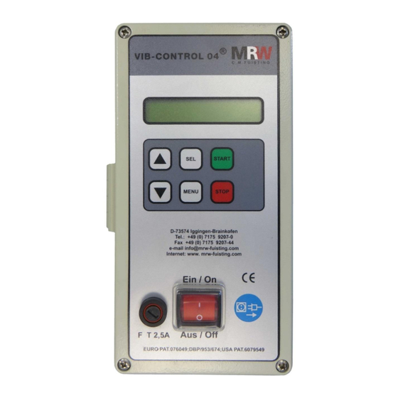
MRW Vib-Control 04 Structure and function 4 Structure and function 1. Display indicates 16 numbers 2. Keypad (membrane keypad) 3. 2.5A slow blow fuse 4. On/off switch Fig. No. 3: 4.1 Operating elements Button Function Menu Opens the menu Start... -
Page 15: Menu List
MRW Vib-Control 04 Structure and function 4.2 Menu list Status display Contin Display Navig. Description Save/ac tiv. button with button button Stop Any time STOP button In order to get to the top level of the menu, always press the “Stop” button... - Page 16 MRW Vib-Control 04 Structure and function Menu display Activ. Display Navig. Description Save button button button Speed input Internal/Buttons Whether the speed is to be controlled via the control unit or via external inputs is External 0-10V = set here. The status of the external inputs xx V is displayed.
-
Page 17: Deactivating The Lock Code
MRW Vib-Control 04 Structure and function Menu display Activ. Display Navig. Description Save button button button Max speed Min speed The minimum permissible speed of the vibratory drive in % is set here. Current limitation Current max X A The highest permissible power consumption by the vibratory drive can be set here. -
Page 18: Explanation Of Special Menu Functions
Instead of bringing in the natural frequency to the target value again with time-consuming work by means of spring configuration, gyrating mass and clearances, the Vib-Control 04 control unit can search for the new natural frequency and operate the device with the new optimal frequency. - Page 19 MRW Vib-Control 04 Structure and function Type of control Three different control types can be set. “Freq+speed contr”: If the frequency was determined via automatic search, the control unit then regulates the frequency automatically when the superstructure is loaded. The feed speed set is then also maintained if the loads are changed.
-
Page 20: Status Messages In The Display
MRW Vib-Control 04 Structure and function 4.5 Status messages in the display 53 % 52.2 Hz Standard display in automatic operating mode Specification of power in %. Vibratory drive work frequency Alternative Alternative setting 4.3 A Output vibratory drive Specification of power in %. Power consumption at input or output 1.8 A... -
Page 21: Defaulting To Factory Settings
Defaulting To default the MRW Vib-Control 04 to factory settings, switch off the device and keep it switched off until the menu display disappears. Then press the two buttons at the same time and switch the device on again. -
Page 22: Installation And Commissioning
Fig. No. 5: terminal strip Tips and recommendations NOTE! The interfaces of the MRW Vib-Control 04 provide an own 24 V potential. An amperage of 0.2 A may not be exceeded here at interfaces in total. 5.3 Prepared X15 connector The X15 connector serves to start or stop a connected vibratory drive with a PLC or with the MRW RoboPot System. -
Page 23: Connection Variant 1
MRW Vib-Control 04 Installation and commissioning 5.3.1 Connection variant 1 A normally open relay is used here to control the Vib-Control 04 with its own potential. If using the MRW RoboPot System, this connection is prepared and a ready-made cable is provided in the accessories. -
Page 24: Prepared X16 Connector
An external potential (PLC) can be passed on here via a normally open relay. For example, an additional Vib-Control 04 which drives a bowl feeder can be controlled via the normally open relay. The interface provides an own 24V potential Pin 1 = 24V, Pin 4 = 0V DC so that a relay or optocoupler can also be connected at this point. -
Page 25: Connection Variant 2
MRW Vib-Control 04 Installation and commissioning 5.4.2 Connection variant 2 The 24V potential of the MRW Vib-Control 04 is used here to control a relay or an optocoupler, which, in turn, controls any load. 27. Oktober 2014 25 v. 34... -
Page 26: X17 Screw Terminal Connection In The Device
MRW Vib-Control 04 Installation and commissioning 5.5 X17 screw terminal connection in the device A minimum waiting period of 5 minutes must be observed after CAUTION! disconnecting the control unit from the power and before opening it Residual voltage so that the charge of the capacitators can decrease to a safe level. -
Page 27: Connection Variant Backup Control And External Power Regulation
MRW Vib-Control 04 Installation and commissioning 5.5.1 Connection variant backup control and external power regulation 27. Oktober 2014 27 v. 34... - Page 28 The feed performance of the vibratory drive can be optionally potentiometer controlled via an external 10kohm potentiometer. The lower and upper limits of the performance programmed in the Vib-Control 04 menu are adhered to. 28 v. 34 27. Oktober 2014...
-
Page 29: Connection Variant External Power Regulation Via Plc
For this reason, the control circuit of the PLC is interrupted via the normally closed contacts, terminals 41 and 40, as long as the Vib-Control 04 has no power 27. Oktober 2014 29 v. 34... -
Page 30: X18 Terminal Connection In The Device
Terminals PE, N and L1 are provided for supplying power to the Vib-Control 04. Here, 110 – 250 V at 50 or 60 Hz must be provided. The power consumption can be 5 A in the short-term. -
Page 31: Spare Parts And Accessories
08-0000453-00 Plug for VIB Control m – Output / Status X4 connecting cable 08-0000044-00 Configured cable for control line for MRW Vib-Control 04 (X15) to MRW Robo-Pot System (X4) Length: 2m Switch, red On / Off 08-0000463-00 Mains switch for... - Page 32 MRW Vib-Control 04 Spare parts and accessories Connector, 4-pole pin for vibratory drive 080000455-00 X 12 32 v. 34 27. Oktober 2014...
-
Page 33: Dismantling And Disposal
Prior to dismantling: Switch off the MRW Vib-Control 04 and safeguard it from being switched on again. Wait at least 5 minutes before opening the housing so that the charge of the capacitors can decrease to a safe level. -
Page 34: Oktober 2014 3 V
MRW Vib-Control 04 Declaration of conformity 8 Declaration of conformity EC DECLARATION OF CONFORMITY The manufacturer MRW DIGIT Electronicgeräte GmbH Osterwiesenstraße 31 D 73574 Iggingen-Brainkofen hereby declares that the design of the machine / system Designation: Control device for electromagnetic vibratory drives...
Need help?
Do you have a question about the Vib-Control 04 and is the answer not in the manual?
Questions and answers