Table of Contents

Summary of Contents for Monroe One-Net SE
-
Page 1: User Manual
FLEXIBLE EMERGENCY MESSAGING PLATFORM USER MANUAL One-Net™ SE & DASDEC™-II Version 3.0 Monroe Electronics, Inc. / Digital Alert Systems 100 Housel Ave • Lyndonville, NY 14098 Provided by: Mega Hertz 800-883-8839 info@go2mhz.com www.go2mhz.com... -
Page 2: Contact Information
FCC Information FCC ID: R8VDASDEC-1EN The One-Net SE and DASDEC-1EN comply with Part 11 (47 CFR 11) of the FCC’s rules for EAS encoders and decoders, including a Declaration of Conformity for Common Alerting Protocol (CAP) compliance, and are registered with the FCC under identification number: R8VDASDEC-1EN. -
Page 3: Table Of Contents
Table of Contents Introduction Icons Highlights Organization Conventions Chapter 1: Hardware Overview Introduction Front Panel Back Panel Chapter 2: Hardware Connections Installation Network Connections Radio Antennas Audio Wiring AES Digitial Audio Wiring Video Wiring General Purpose Input/Output (GPIO) Serial Port Wiring MPEG Encoder Card Wiring Power Connections Chapter 3: Initial Setup... - Page 4 Demo/Practice Setup Net Alert Setup GPIO Setup Printer Setup Alert Storage Setup Chapter 6: Alert Events Tab Incoming Alerts Incoming/Decoded Alerts Forwarded Alerts Originated/Forwarded Alerts Originated Alerts All Alerts Chapter 7: Send Alerts Tab General Alerts One-Button Alert Custom Message Chapter 8: System Tab Help Status...
- Page 5 Provides a link to additional information on an external website, such as the FCC. Internal Link Provides a link to additional information on the Monroe Electronics or Digital Alert Systems website. Glossary Proivdes a glossary definition for a term used in the manual.
-
Page 6: Organization
Chapter 4, Web Interface and comments, and Navigation. suggestions to Monroe • An electronic version of this manual is available on the Monroe Electronics and Electronics at eas@ Digital Alert Systems websites, www.monroe-electronics.com monroe-electronics.com. -
Page 7: Chapter 1: Hardware Overview
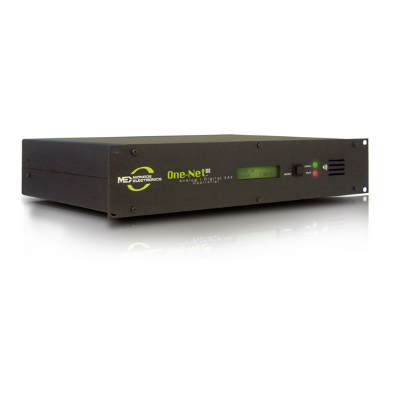
Hardware Overview INTRODUCTION The One-Net and DASDEC are 2U rack-mounted EAS devices utilizing standard computer technology in a dedicated chassis with broadcast quality connectors. The PC motherboard uses industry standard connectors for USB, PS/2, serial, VGA, HDMI, networking, and audio. In addition to the standard motherboard connections, the platforms feature broadcast quality video, audio, antenna, contact closure, and power connectors. - Page 8 • If the system software is manually stopped or temporarily restarted due to an internal problem, the LCD displays a Server Stopped message until the software restarts to a ready state. • During the decoding of an incoming alert, the LCD displays information about the source and the stage of the decoding.
-
Page 9: Back Panel
Select Button The Select button on the front panel is used to manually initiate a Required Weekly Test (RWT), or to acknowledge unforwarded active alerts. • Press the Select button once to being a manual RWT; the second line of the LCD displays Press again for RWT. -
Page 10: Chapter 2: Hardware Connections
Hardware Connections INSTALLATION Caution The One-Net and DASDEC frames mount in an EIA-compliant equipment rack by means The rack and screws of four rack screws fastened through the front mounting ears. should be sufficient to carry the load of For safe, long-term reliability: the unit, including the weight of accompanying •... -
Page 11: Radio Antennas
RADIO ANTENNAS If the EAS device is equipped with internal radio receivers, there will be industry Note standard F-type connectors for each receiver (up to three total). Review your states’ The FCC provides a Emergency Alert System Plan for the appropriate monitoring assignments; these listing of each state’s assignments will assist in determining the proper antenna for the frequencies that EAS Plan, along with... - Page 12 Back Panel Analog Audio Wiring The first type of inputs connects to internal EAS decoders (8, 10). These inputs are Note A dual RCA to 3.5 mm utilized to process broadcast EAS messages, and are attached to external radio jack input adapter can receivers or other EAS equipment.
-
Page 13: Aes Digitial Audio Wiring
Analog Audio Outputs There are two types of Analog Audio Outputs: EAS Audio and Program Audio. The EAS Audio output provides EAS decoded audio only. The Program Audio output provides decoded EAS audio. When Program Audio inputs are connected to an incoming audio source, these outputs deliver a switched program signal. -
Page 14: General Purpose Input/Output (Gpio)
GENERAL PURPOSE INPUT/OUTPUT (GPIO) The EAS platform comes standard with two General Purpose Input (GPI) contact closures and two General Purpose Output (GPO) relays. They are located in the upper middle of the back panel (3) via a 7-pin pluggable terminal connector. GPIO Terminal Connector GPO relay outputs are programmable. -
Page 15: Serial Port Wiring
SERIAL PORT WIRING This feature is specific to the DASDEC II. Each EAS device is equipped with one RS232 serial port on the back panel. The serial ports connect to and drive a variety of external video character generators and Note BetaBrite LED signs. -
Page 16: Power Connections
POWER CONNECTIONS Warning The safe operation of Once all connections are completed, power can then be applied to the device. A panel- this product requires mounted IEC compliant AC power receptacle, found in the lower left corner of the that a protective earth device’s back panel (19), delivers power to the internal AC power supply. -
Page 17: Chapter 3: Initial Setup
Initial Setup MAKING FIRST CONTACT The One-Net and DASDEC platforms contain an embedded web server that allows you to effectively communicate with the EAS platform via a standard web browser. Changes to configurations/control settings, initiating EAS alerts, and viewing EAS alerts are all performed through familiar web browsers such as Apple Safari, Google Chrome, Microsoft Explorer, or Mozilla Firefox. - Page 18 Direct Connection Note Write down the current IP address and subnet mask settings of your local computer before making changes. This information will be useful when reconfiguring back to its original settings. Direct Connection Attention 1. Connect one end of the factory supplied CAT-5 network crossover cable to the It is advised that you Main Network Interface port (12) at the back of the EAS device, and the other end contact a network...
-
Page 19: Web Interface Login
Hub/Switch Connection Note If you are attempting to perform the following procedure, existing network settings within these additional network hardware components may prevent the ability to communicate with the EAS device. Hub/ Switch Connected Attention Consult with a network The primary difference between this type of connection and the direct connection administrator to method is the inclusion of additional networking hardware. - Page 20 Launch a web browser application from a computer located on the same local area network (LAN) as the One-Net or DASDEC device you intend to reach. Type Note Multiple login sessions the EAS devices’ IP address in the address bar of the web browser (for example, are allowed at the same http://192.168.0.200).
- Page 21 Server Network Configuration Screen 5. Enter the new IP Address and IP Netmask (or subnet mask) in the appropriate fields (located in the large green section on the right side of the screen). If the IP Address of Gateway and DNS information is available, enter that information as well.
-
Page 22: Tabs, Buttons, Hyperlinks, Pull-Downs, Check Boxes And Text Fields
Web Interface and Navigation You will communicate with your EAS device by logging into the web interface via a web browser. Type the IP address of the device and enter the proper credentials (username and password). Click the Login button. See the previous chapter (EAS Device Login) for more detailed login information. - Page 23 Pull-Down Menus Allow users to select from a list of predefined configuration parameters. Many pull-downs have static selections, but several have selections that change according to modifications made in the EAS unit. Click on the pull-down menu to see a list of selections;...
-
Page 24: Web Interface Layout
Hyperlinks Text elements that are highlighted in blue and underlined link to another location within the web interface, or to the World Wide Web. Hyperlinks assist in navigating the many menus found in the web interface. Click on a hyperlink to navigate to the indicated location. - Page 25 Device Banner: The Device Banner, located in the upper right-hand corner of the web interface, displays the EAS model, software version, and last loaded configuration file. One-Net models have a Monroe Electronics logo, followed by One-Net R189 Analog/Digital CAP/EAS Encoder/Decoder. The DASDEC model have the Digital Alert System logo, followed by DASDEC-1EN Analog/Digital CAP/EAS Encoder/Decoder.
- Page 26 • Navigation Tabs & Radio Buttons: The web interface contains dozens of unique Attention Using the back/refresh screens; they are organized with a system of tabs and radio buttons. The main tabs buttons on your web located across the top of the header are: Setup, System, Alert Events, and Send browser can provide Alerts.
- Page 27 The body of the web interface is where all configuration, status, and alerting information is displayed and modified. The navigation controls (tabs, radio buttons, and hyperlinks) change the body section. This manual discusses each section in detail. Footer Web Interface - Footer Section At the bottom of each web interface page is a row of hyperlinks, broken into the following sections: Navigation:...
-
Page 28: Web Interface Navigation
WEB INTERFACE AND NAVIGATION The web interface is used to set up, control, view status, and monitor all activity. Radio buttons, check boxes, text fields, pull-down menus, and hyperlinks are found throughout. The web interface uses a hierarchical organizational structure to navigate dozens of screens. - Page 29 Pages with an Accept Changes Button Attention On pages with an Clicking Accept Changes updates the screen information. If the user exits the screen Accept Changes button, without clicking this button, the web interface usually prompts the user to “Submit you must use that but- changes first?”, and the user will decide to accept or decline those changes.
-
Page 30: Chapter 5: Setup Tab
Setup Tab Setup Tab The majority of all configuration settings are within the Setup tab. There are 14 sub-categories, accessed by clicking their individual radio buttons. These categories are as follows: Description Radio Button Server License Keys, Saving/Recalling Configuration Settings, Upgrades, and general system options Station Global and station origination/forwarding settings... - Page 31 Main/License: Server Name & License Key Configuration Main/License Sub-Tab Screen There are two main sections on this screen: Platform ID and License Key Configuration. Use this screen to set the Server Name of the device and enable licensed features. There are several crucial action buttons at the bottom of the screen to restart, reboot, and power off the server.
- Page 32 Licenses cannot be copied or shared between devices. To purchase a license key for a feature, contact Monroe Electronics/Digital Alert Systems. New license keys are typically sent via email, and can be easily copied and pasted into the corresponding license key text field.
- Page 33 Restarting the software logs all users off the device and shuts down all operations until Note To restart the EAS the software is reloaded. Once reloaded (approximately 45 seconds), users will need to devices server log in to the device. After the restart, it is a good idea to verify that the recently added software, click the license key is properly installed by navigating back to the corresponding license key Restart Server?
- Page 34 License Key Description V3.0 En- A Version 3.0 Enabling key is necessary to operate the version 3 abling Key software, and is preconfigured for each new device. Provides full FCC 6th R &O compliance and the exclusive Alert Agent™ with Alert Node processing.
- Page 35 Network Enables the Triple Port Gigabit Ethernet Expansion hardware option More information on Expansion (One-Net SE/DASDEC-II ONLY), creating controls for four unique network expansion is Ethernet 10/100/1G network links. Please contact the factory available on the Digital regarding upgrading in-field units.
- Page 36 (External ATSC or DVB data receiver and antenna required; not included.) CAP IPAWS Server Enables any One-Net SE or DASDEC-II device to emulate an Emulation IPAWS server. Contact factory for more details. Net Alert Licenses A grouping of network-based communication protocols.
- Page 37 License Key Description EAS NET™/CAP Send Adds the ability to send multi language CAP messages OmniLingual™ CAP between EAS Net devices. Also Requires Valid Multi Language key. EAS NET™ Adds EAS-Net support for Microsoft/Ericsson Mediaroom. This Mediaroom license key is a bundle that includes EAS-Net. EAS NET™...
- Page 38 License Key Description OmniLingual™ OmniLingual module enables automatic alert translation from Note Enable Key conventional EAS or CAP sources into one or more languages OmniLingual™ — including, but not limited to, English, Spanish, French, Enable Key: Requires German, Italian, Hmong, and Somali — for EAS text display appropriate Premium and TTS audio conversion and output.
- Page 39 Edit Voice Screen At the top of this screen are three action buttons: Accept Changes, Cancel Changes, and Apply Changes. For convenience purposes, they are replicated farther down the screen. The Apply Changes button will activate any changes made within the word definition area, along with the Words per minute and Pitch factor percent text fields.
- Page 40 Attention This list of phonemes are the only letter combinations the TTS engine will recognize. Make sure to click Notice all vowel phonemes are immediately followed a number (0 or 1). These the Apply Changes numbers are emphasis values, where the 0 de-emphasizes that phoneme, and a 1 em- button after making phasizes that phoneme.
- Page 41 Lexicon Table Text File Lexicon Tables (or Word Definitions) can be saved for archive purposes. Alternatively, a Lexicon Table may be transferred to another Premium Voice within the same EAS device, or any other EAS device. To view and save a Lexicon Table, click the View/ Caution When uploading a Download the current saved lexicon file hyperlink at the bottom of the Sample Text...
- Page 42 Server Configuration File Management The Setup > Server > Configuration Mgmt screen is used to store, manage, and recall configuration backup files. You can create a copy of the current configuration settings and review previously saved configuration files. Each configuration backup is stored in an encrypted ZIP file that contains all settings selected in the setup process.
- Page 43 management options appear, such as a Download selected configuration file option, a Rename Selected Configuration File text field and action button, a Delete File button, and an Install button. A No previous configuration yet message is displayed before any backup configuration files have been installed.
- Page 44 date/time. Selecting the Download selected configuration file… hyperlink will allow you to save the file. Make sure to save it on your computer. Do not unzip the file. The first time you attempt to download a configuration file, a prompt will be presented, requiring authentication.
- Page 45 Backup button. For safe upgrades will have multiple software files that need to be installed individually. New keeping, download the software upgrade files are periodically available, and can be obtained from Monroe backup configuration Electronics/Digital Alert Systems Customer Service. file from the same page to a host computer for safe keeping.
- Page 46 When upgrading from version 2.x software to version 3.0, users will need to purchase system is running a a V3.0 software license key. Once purchased, Monroe Electronics/Digital Alert Systems software version below will provide the user with a V3.0 Enabling Key, a link to download the V3.0 software, V2.0-2, please contact...
- Page 47 • Passwords must contain a minimum of 8 characters. • Passwords must contain both letters and numbers. • Commonly used (and blacklisted) passwords are not allowed. The following strings of text are forbidden in any password. These are not case sensitive; any combination of upper and lower case is disallowed.
- Page 48 Server Name and License Key Configuration Screen To enter the V3.0 Enabling Key: 1. If not already there, navigate the interface to the Setup > Server screen (Server Name and License Key Configuration). 2. Enter the provided V3.0 Enabling Key into the appropriate text entry field 3.
- Page 49 The Setup > Server > Options screen is designed to interface with various platform options. These include enabling debug logging, USB port speed, text encoding, CAP output encoding, and Monroe Electronics Model 988 Clock Sync support. One-Net/DASDEC User Manual v3.0 | r0616...
- Page 50 Serial sub-tab. Data being sent and received between the EAS device and the CG will on unless directed by be documented in the Serial Port Server Log, found on this screen. When the Server a Monroe Electronics/ Debug Log Interface is enabled, those changes are immediate and a hyperlink titled Digital Alert Systems Link to Debug pages is made visible, and navigates them to the System >...
-
Page 51: Network Setup
When exclusively communicating with Monroe Electronics/Digital Alert Systems EAS equipment, this setting can be left unchecked. The Monroe Electronics Model 988 is an interface enabling local authorities secure access via telephone lines to activate the attached EAS device for preselected areas with alarm message and allows the caller to record an emergency voice message to be played during the alert. - Page 52 Server Network Hostname, Network Ethernet IP Addresses, Gateway, and Static Routes. It also displays extensive network configuration information such as Network Routing Table, Static Routes, Network Configuration Settings, DNS Configurations, Network Host, and Network Device Settings. Recent EAS device models include two network interfaces (or NIC). Each NIC can be configured with individual IP addresses, either by manually entering a static IP address (recommended) or by selecting DHCP to automatically assign network addresses.
- Page 53 Network Interface Configuration To configure a network interface, first locate the desired Network Interface configuration box (shown in green above) and determine the appropriate Network Type. The Network Speed pull-down menu is used to select a fixed network speed for that NIC, or select Auto (recommended), and the NIC will automatically select the appropriate speed.
- Page 54 for configuring the second NIC. Note An optional Gigabit Ethernet Expansion kit The Network Interface box has three different color status: (factory installed) will increase the overall • Green: Valid settings and operational. The box is labeled Network is *Enabled* in NIC count to four.
- Page 55 Server Network Configuration Screen (Network Status Information) Static Route Configuration This simple interface allows statically defined network routes to be configured, en- abled/disabled and added/deleted at network startup. To configure a static route: 1. Click the Add Static Route button within the Static Route Configuration section of Note the screen.
- Page 56 Security: Server Network Security Configuration This page provides controls for managing network security. Two features are configurable for network security: • Switching web access between secure mode (HTTPS) and regular mode (HTTP). • Managing Secure Shell (SSH) keys across multiple platforms. Server Network Security Configuration Screen Web Interface Access Security Use the Web Interface Access Security check box to force HTTPS SSL-based...
- Page 57 DO NOT MODIFY an private key pair must be authorized on the remote platform. SSH Keys without consulting with Monroe Authorization is usually achieved by copying the public key into a file on the remote Electronics/Digital Alert host. The EAS device uses the open source package OpenSSH for SSH features stored Systems.
- Page 58 SSH Key Management Interface Screen Once a remote host client descriptor interface is added, it must be configured. Default values for SSH connection to the remote host are provided (except for IP address). 1. Change the following: • Interface Name •...
- Page 59 • Key Mgmt Status: This will attempt to retrieve the current state of the EAS device key management status from the remote host via SSH. • Get Public Key: This will attempt to retrieve the public key from the remote host via SSH.
-
Page 60: Time Setup
Proxy Screen To configure a proxy server with the EAS device: • Check the Use proxy server settings? check box. Two text fields will appear: one for an HTTP proxy server, and the second for an HTTPS proxy server. • Enter the server name into the appropriate text field. - Page 61 To manually set the time: Attention If time zone is changed, or if the time is set 1. Use the pull-down menus to set the month, date, and time zone fields. forward far enough, 2. Enter the desired year, hour (24 hour format), minute, and seconds into the the server software appropriate text fields.
-
Page 62: Users Setup
USERS SETUP Note User account settings The Setup > Users screen is used to manage user accounts within the EAS device. within the web Administrative level users have the ability to add/delete user accounts, change account interface are separate passwords, and set user permission levels along with a few additional features. The from the Linux system Users Setup Screen is divided into two sections: Edit Server User Account Profile (left user accounts. - Page 63 Permission Level Description Administration Level Unlimited permissions Attention Operation/Control Level Everything EXCEPT: It is recommended • Upgrades to create individual • Software Licensing user accounts for • Debug Log enable/disable each staff member • Web interface user setup/modification requiring access to •...
- Page 64 • The EAS device will visually alert users with passwords older than 180 days. Edit Server User Account Profile The Add New Server User Account section is where new user accounts are created. Only Administration Level users have access to this section of the web interface to add user accounts.
- Page 65 Enter unused login name Click in this text field to create and enter an unused (or unique) user login name. The login name may consist of up to 32 characters—including letters, numbers, and punctuation characters. The EAS device will reject attempts to enter a login name that is currently in use.
- Page 66 Edit Server User Account Section User Account pull-down menu Click and select the user account from this pull-down menu. Information about the selected user’s current login and last logoff is displayed just below this pull-down menu. This pull-down menu is only available to Administration Levels users. Allow user to change password When checked, this setting allows the user to change their own password.
- Page 67 Login Screen with Decoder Status Display Display decoder status on Login page In some situations, it is advantageous to see the internal radio and audio decoder status along with the CAP decoder status without logging into the EAS device. This check box will display that information on the login screen.
-
Page 68: Email Setup
a visual warning. Submit Changes? When clicked, this button will submit any changes. It is not necessary to use this button after selecting any of the above check boxes for their changes are immediate. Cancel Changes To cancel any proposed changes and refresh the screen, click the Cancel Changes button. - Page 69 Sub-Tab Description EMail Server Configure and test the outgoing mail settings. Event EMail Select which types of event and server access reports are delivered. Decoder EMail Select alert decoding and/or alert forwarding emails. Encoder EMail Select alert origination emails. EMail Server This sub-tab is where the outgoing mail settings are configured.
- Page 70 Many e-mail services require a valid e-mail address in order to send e-mails. In these cases, enter the appropriate e-mail address into the From Name text field and check the Have Email MTA use From name as sender check box. The Restart Sendmail button will restart the internal mail client process.
- Page 71 Server Event EMail Configuration Screen The Event EMail sub-tab is broken into two functional sections: EAS Event Reports and Server Access Reports. Each of these sections begins with an Email To: text field. A single or multiple e-mail addresses (separated by a comma and no spaces) may be entered into these fields.
- Page 72 any updates and refresh the screen. Decoder EMail To set up the outgoing email for decoder events, select Setup > Email > Decoder EMail. • E-mails can be sent upon alert decoding. • E-mails can be sent upon alert forwarding. Check the appropriate check box and add the desired recipients’...
-
Page 73: Audio Setup
AUDIO SETUP Attention Due to the need for immediate feedback Audio is at the heart of an EAS system. Because the EAS devices is configured ready for when tuning audio, average field situations, the Emergency Alert System requirements in your specific area the Setup >... - Page 74 Direct Audio Output Level and Tests Screen Note The same Audio Output Audio Output Sample Rate Sample Rate control Controls the sample rate of audio played from the EAS device. The default sample rate is presented within is 16000 samples/second. the Setup >...
- Page 75 Audio Tests There are two audio test options: • Play a test tone of 960 or 853 Hz or the EAS attention signal for the time entered the Tone Test Duration (1 to 180 seconds) field • Play an audio WAV file from the Test Audio File pull-down menu Selected files display: ◊...
- Page 76 Setup > Audio >Radio Tuners screen. be purchased through Each radio is tuned/configured via the web interface to any AM, FM, or NOAA third party vendors. frequency. For recommendations, contact Monroe Electronics / Digital Alert Systems. One-Net/DASDEC User Manual v3.0 | r0616 5-47...
- Page 77 Note It is important to tune the radios to stations that carry EAS alerts. This is a fundamental part of properly setting up the EAS device. Consult your states’ EAS plan for the monitoring assignments in your area. Caution Do not leave the monitor on during normal operations.
- Page 78 Decoder Audio: Alert Decoding Audio Configuration The Decoder Audio page has three areas to configure: • Alert Decoding Audio Configuration • Decoder Audio Monitoring Configuration • Alert Forwarding Audio Configuration • ALSA Sound System (Administration Level users only) Note The AES digital audio Each EAS decoder channel can be independently tuned for input sensitivity and can card does NOT support be enabled and disabled.
- Page 79 Alert Decoding Audio Configuration Screen The audio soundcard table columns are: Decoder Name, Label and Info • The decoder base name, automatically set by the server, provides an identifica- tion tag for the decoder • This input text field provides a description of the decoder channel that will be used throughout the interface.
- Page 80 Elevated (yellow) High (red) • Use the Refresh button in the header of the page to make multiple checks of the Audio Level Status quality. This will assist in setting the correct level setting. Snapshot Each decoder is also given a Snapshot button. When clicked, a WAV file of the cor- responding decoder audio input buffer is saved, dated, and displayed as a web link accessible via this web page.
- Page 81 Decoder Audio Monitoring Configuration Note The selections occur Two interfaces in this section for users to select the desired audio source and select immediately and the appropriate monitor output to hear the audio from. will cause a page The Select Decoder Audio to Monitor list shows all the available decoder audio •...
- Page 82 Note The same Audio Output Sample Rate control can also be found in the Setup > Audio > Audio Output Levels/ Tests (Direct Audio Output Levels and Tests section) and Setup > Audio > Encoder Audio (Alert Encoder Audio Configuration section). Changing the setting in one location will change it in all locations.
- Page 83 Alert Audio Delay Note This same control Used to control a delay period before the playout of alert audio, after the EAS is presented within Audio playout relay is closed. When enabled, a numeric text field is provided for the Setup > Audio entering a user specified number of seconds of delay.
- Page 84 Audio Output Sample Rate This selector controls the sample rate of audio played from the EAS device. Main Audio and Auxiliary Audio Tables These tables allow for examining audio output status and enabling/disabling playing Main station Originated alert audio on the individual audio output devices. •...
-
Page 85: Video/Cg Setup
Record Input Level Use the Input Level control to set the level for the recording input gain level. Enter a value from 0 - 100 in the Record Input Level field. After you set the value, you must click on the text ‘click here to activate changed value’. VIDEO/CG SETUP Select the Setup >... - Page 86 Serial Port Character Generator Configuration The radio selection buttons show the Character Generator (CG) used when a decoded alert is forwarded or encoded (or no CG). There are eight supported character generator protocols: • Monroe R194 CG • Monroe CEMS-0500/1000 • Standard TFT •...
- Page 87 The CG should be connected to the server serial port (on the back panel) using the correct serial cable (TFT, CODI, VDS use NULL modem cable, Monroe CGs use straight through cable, SAGE Generic depends on specific CG, usually a straight through cable).
- Page 88 Note If activating FIPS Groups and/or EAS Groups are configured, then the serial port CG will only be activated during alert origination or forwarding when the alert contains at least one of the FIPS Group codes and matches at FIPS and EAS Codes Properties Configuration Section least one of the EAS Group codes.
- Page 89 The supported protocols and their options are listed next. 1. Monroe R194 CG Settings • No attributes to set. This is only available on the Main Serial port. 2. Monroe CEMS 500/1000 CG Attribute Settings • Repeat Alert Video Display – Defaults to Do Not Repeat. •...
- Page 90 TFT Pre-Alert Notification omit audio play-out • Check to play audio if TFT client requests EAS alert audio play-out. If disabled, the audio requests will be immediately answered without audio play-out. TFT client relay command emulation – Defaults to disabled. •...
- Page 91 Delay crawl – Defaults to disabled. • When enabled, the crawl is delayed until after the EAS audio header and attention two-tone signal is played. Repeat Alert Video Display – Defaults to Do Not Repeat. Select from a set of options for repeating the data write to the remote device after a pause period set from the Set Alert Video Repetition Period field.
- Page 92 Text over Video Anti-aliased – Defaults to enabled. • When enabled, the text is anti-aliases over the video background. Iterations – Defaults to one. Crawl is done once. • Set from 1 to 100. Speed – Defaults to 240 Pix/second. •...
- Page 93 There is a button to test the BetaBrite display, and one to stop the test. The test consists of crawling the date and time for about 30 seconds. 11. Monroe Envoy No attributes to set. This is only available on the Main Serial port.
- Page 94 Video Out Screen Internal CG full page video output Use the checkbox to enable or disable the Main station Video Output if licensed and Note When MultiStation the hardware support is enabled. The EAS device can provide a full screen NTSC analog video display of the current originated or forwarded alert.
-
Page 95: Alert Agent Setup
ALERT AGENT™ SETUP Version 3.0 introduces a few new concepts to give users better control and functional- ity when configuring the EAS device and managing EAS alerts. The Alert Agent™ radio button is new. It combines many existing feature and functions from previous software versions and adds Alert Nodes, FIPS Location Groups, and EAS Code Groups. - Page 96 Alert Policies Screen Decoder Alert Languages This setting enables users to select the languages used within the EAS device. The de- fault is English. Multiple languages may be selected using the SHIFT or CTRL keys. Configure Duplicate EAS Alert Handling for Decoder Auto-Forwarding An incoming EAS alert that is an exact duplicate of a previously decoded alert, is completely discarded and a message is logged in the operation log.
- Page 97 Configure Pending Alert Acknowledgment (Requires a Plus Package License Key) When an EAS alert is decoded during Manual forward mode, while active, it causes the red front panel status light to flash until the alert is acknowledged. Alerts can be acknowledged from the Alert Events >...
- Page 98 Manage Alert Nodes Screen The Manage Alert Nodes screen is divided into two sections: an Alert Node test (top of screen) and a list of Alert Nodes in order of priority (from top to bottom). Incoming decoded events will be evaluated by the top Alert Node and will continue down the list. The EAS device is pre-configured with four Alert Nodes –...
- Page 99 Alert Nodes are simple to configure and have four basic components: • Name • Node Criteria • Action • Action Definition Name When adding a new Alert Node, the EAS device creates an Alert Node name (a combination of letters and numbers). Edit this name to be more descriptive of the Node’s purpose.
- Page 100 > EAS Code Groups sub-tab and can quickly be accessed by clicking the Event Codes hyperlink. Only one selection may be made from this pull-down menu. Orig (Originator) Codes This is a three character ASCII code found in an EAS header which denotes the source of an EAS alert.
- Page 101 • During Auto-Forward Mode – will automatically forward the EAS alert defined in this Alert Node when the station is in Auto-Forward Mode. When in Manual Forward Mode, users will need to manually forward the EAS alert via a GPI or web interface. • Force Now –...
- Page 102 Post-Alert Audio Audio WAV files can be uploaded to the EAS device and played after the EAS alert audio. This pull-down menu displays all the available audio WAV files stored on the EAS device. Select the desired file by clicking it in the list. The selected file will play after the EAS alert defined within this Alert Node.
- Page 103 MultiStation Mode When utilizing MultiStation Mode, Alert Nodes will enable separate Alert Definition settings for each station. When a Node Criteria is matched with the incoming EAS alert, each stations’ Alert Definition settings can be configured separately. Forwarding Action, Play Scheduling, GPI Hold, Pre-Alert Audio, Alert Audio, Post- EOM Omnilingual Audio, and Post-Alert Audio settings can be defined for each station.
- Page 104 Input Source This pull-down menu contains all the available sources (radios, CAP/IPAWS, and EAS-NET™, etc.) where an alert might be received. Select a source by clicking on it. Only one source may be selected when testing an Alert Node. EAS Code Select the desired EAS Code from this pull-down menu.
- Page 105 Local Access Forwarding Screen Custom Text Translation for CEM (Civil Emergency Message) This check box controls activation of the local access forwarding feature. When enabled, as shown in the above screen shot, local access forwarding is active and can be configured. If a local access CEM alert is decoded, it will be automatically forwarded regardless of the decoder forwarding mode.
- Page 106 The same Stop Active Message button is available for the active alert displayed in the Alert Events > Incoming Alerts and Incoming/Decoded Alerts screens. Incoming/Decoded Alerts Custom CEM Text Translation This text, if provided, will be displayed on the video details page and sent to CG’s and to network protocols (like EAS NET, SCTE18, etc.) when the alert is forwarded Note...
- Page 107 Number of repetitions The Message Display Control option “Repeat CEM alert play-out for a fixed number of times” is for selecting the number of times the CEM alert is re- played. Replay period The repeat period interface for Message Display Control options that cause repetition for certain time durations, can set the replay period to the time in minutes/seconds between end of play-out and replay.
- Page 108 Text Message to Speech Options This drop down menu gives the EAS device the ability to use a text-to-speech engine on EAS NET decoded custom alerts. There are three options: • Never use message text-to-speech • Use message text-to-speech only if Audio not present • Always use message text-to-speech.
- Page 109 Manage FIPS Location Group Lists This section of the screen displays a list of existing FIPS Groups and enables users to add, edit, duplicate and delete FIPS Groups. A brand new EAS device will not have any configured FIPS code groups - they will need to be added on this screen. If the EAS device has been upgraded from a previous version of software to V3.0, FIPS groups will be automatically created.
- Page 110 To edit a new or existing FIPS Group, click the corresponding Edit button. User have the ability to change the name and add/remove FIPS codes within this group. The following fields, pull-downs, and buttons are available: Name The EAS device automatically generates a name for new FIPS Group. Highlight the text and enter a descriptive name for this group of FIPS codes.
- Page 111 Accept Changes This button will finalize any additions, edits, and/or deletions made while edit- ing a FIPS code group. Once clicked, the Edit FIPS group section of the interface will be removed and the screen will return to its normal state. Cancel Changes Pressing this button will cancel any changes made to the FIPS group and return this screen to its normal state.
- Page 112 Remove Selection FIPS code can be removed from the FIPS codes list by selecting the item and clicking the Remove Selected button. EAS Code Groups EAS Code Groups are new in V3.0. There are numerous places to enter EAS codes within the web interface.
- Page 113 in the Setup > GPIO screen will be named here as GPO.1. Add New EAS Group To add a new EAS Group, first click the Add New FIPS Group button. A new EAS group will appear at the top of the EAS Code Group Lists and have an automatically generated name starting with a series of numbers and ending in ‘_EAS’.
- Page 114 this field and enter a descriptive name for this group of EAS codes. Choose from All EAS Codes: This area contains all the EAS codes. It is from this area (and the Quick Add but- tons just below) that EAS codes are added to the EAS codes list for this group. Make a selection by clicking on the desired item.
-
Page 115: Station Setup
Configure Available EAS Types for Encoder Alert Origination Section Choose from All EAS Codes: This area contains all the EAS codes. It is from this area (and the Quick Add buttons just below) that EAS codes are added to the EAS codes list for this group. Make a selection by clicking on the desired item. - Page 116 Sub-Tab Description Global Options Configuration of global origination (Required Weekly Tests) and forwarding settings. Auto-Forward Mode settings are found here. Main Station specific ID, language settings in addition to origination and forwarding settings When using MultiStation mode, the web interface displays additional sub-tabs, one for each station and a simultaneous station override sub-tab.
- Page 117 Global Options Block Origination and Manual Forwarding during in progress alert announcement Check to block manual play-out of a new alert while another announcement is in progress. If left unchecked, the alerts will play sequentially. Use separate EAS Station IDs for Origination and Forwarding Enables the user to configure a different EAS Station ID for the Origination Settings and the Forwarding Settings.
- Page 118 Global Forwarding Settings Configure Auto or Manual Forwarding Operation One essential decision that an EAS participant must make is whether to run an EAS decoder in Auto-Forward mode or Manual Forwarding mode. This section provides the controls over these two options. The text box on the left side of this section indicates the current forwarding state.
- Page 119 Other Options Use EAS NET originating unit station ID when forwarding an EAS NET received alert Check to enable. Front Panel Button press will release Held alert Allows front panel button to release an alert held pending GPI closure. Forward audio message in decoded Weekly Tests If a decoded Required Weekly Test (RWT) has audio, it will be forwarded.
- Page 120 Main Sub-tab Screen Origination Settings EAS Origination (ORG) Code The ORG code is a standard part of the EAS audio protocol. It is placed in the EAS alert message when the encoder originates an EAS alert. The same code is used for forwarded alerts.
- Page 121 Set the play scheduling for the originating alert. The options are as follows: • As soon as possible (default) • As late as possible • Top of next minute interval (MM:00) • Next 30 sec interval (MM:00 or MM:30) • Next 20 sec interval (MM:00,MM:20,MM:40) • Next 15 sec interval (MM:00,MM:15,MM:30,MM:45) • Next 10 sec interval Weekly Test Settings...
- Page 122 Time Configuration Notes • When configuring the time period, if first time is greater than the second time, the alert will be scheduled at a random time from 0 hrs. Midnight to second time or first time to 23:59. If the first time period is less than the second, the alert will be scheduled at a random time between the first and the second time entry.
- Page 123 Simultaneous Station Override Sub-Tab The Simultaneous Station Override sub-tab has the same controls as the Main sub-tab did. The simultaneous override configuration settings are used when no stations are enabled, for national alerts, and for override alerts played once to all stations. Weekly Test Settings are only available in this sub-tab if every station sub-tab is disabled.
- Page 124 Station 1 Sub-Tab The majority of the Station sub-tab configuration settings are described in the Main Sub-tab (above). The following descriptions will highlight specific differences. General Station Settings Station Configuration Interface Name Text field that labels the Station sub-tab. The purpose of this name is to label the sub-tab and is not used or included in any EAS alerts messages.
- Page 125 Due to the limited number of audio outputs in relation to the number of stations require proper controlled by the EAS device in MultiStation mode, Monroe Electronics / Digital Alert setup prior to being Systems provides an optional MultiPlayer. The MultiPlayer is a separate 1RU chassis configured in this that provides up to 5 completely independent EAS audio channels playable at any time.
- Page 126 Origination Settings The Origination Settings are exactly the same with the exception of the Encoder Output Audio Devices settings. Encoder Output Audio Devices A list of available encoder output audio devices is presented. Select the desired output and click the Submit Selection Settings. Multiple selections can be made by using the CTRL key when making selections.
- Page 127 DEMO/PRACTICE SETUP Warning BE CAREFUL! Forwarding any Demo/Practice This page allows you to enable the Practice/Demo operation mode. You can configure Warning (DMO) will alert parameters for a practice and test run of decoding and forwarding. By generating take it to AIR. Examine if a trial decoded DMO (Demo/Practice Warning) alert, rather than having to wait until an Auto-Forward Mode is actual alert is received, you can simulate the behavior of any incoming decoded alert...
- Page 128 selections can be made using the CTRL key when making selections or they can be added one at a time. Current FIPS locations for One-Button DEMO Decode/Forwarding Test Contains a list of FIPS codes intended for use with the Demo/Practice Warning test. Each FIPS code has a pull-down menu for subdividing the FIPS location.
- Page 129 If a required network interface is not available, it can be enabled using the License Key Manager interface under Setup > Server > Main/License. (See the Server Setup - Main/License section of this chapter) License keys may be purchased from Monroe Electronics / Digital Alert Systems.
- Page 130 DVS168 Sub-tab Alert Forwarding to DVS168/EARS device. Placing a check in this box will allow received EAS alerts to be forwarded through the EAS device and sent out using the DVS-168 protocol. A gray DVS168/EARS client 1 connection info interface will be displayed when this options is checked. Encoder Alert Send to DVS168/EARS device.
- Page 131 Remove the check mark from the box that says All EAS codes trigger the DVS168/EARS device to enable EAS forwarding control. When configured, select an EAS code group that will be used to check against the incoming forwarded alert. If any of the EAS codes are included in the incoming forwarded alert, the alert will be sent to the DVS-168 client.
- Page 132 There is only one check box button to enable EAS NET decode. Check the check box labeled EAS_NET decode from remote EAS NET sending devices. The EAS device will then be able to receive alerts sent via EAS NET send from a properly configured remote EAS device.
- Page 133 Audio Output Sample Rate The correct value for this depends on the destination. For audio to a remote EAS device EAS NET decoder, use the output sample rate selected on the remote EAS device. Choices are 16000, 32000, 44100, and 48000 samples/sec. Pre-Alert audio/alert header/attention inclusion at start of audio stream Alert EOM Audio Streaming These two check box options are included for control of the total content of the alert...
- Page 134 Configure EAS NET Client Connection Section Configure EAS_NET Client Connection Once enabled, you can create configurations for up to 8 EAS_NET clients. Each client Caution can be independently enabled and disabled, allowing an easy way to stop or restart a EAS_NET client client for a specific region.
- Page 135 Various information fields must be configured to identify and correctly communicate to the EAS NET remote client. Common to all are: Client Interface Name - This text box allows the user to give the client interface a descriptive name. These names appear in the selection list. Client Enable/Disable - This check box enables and disables the EAS NET client.
- Page 136 option is licensed. A TCP socket is used to communicate an EAS event notification as per the Minerva protocol. • WideOrbit – This is a special protocol bundled under EAS NET when the EAS NET Automation option is licensed. • RCS Nexgen – This is a special protocol bundled under EAS NET when the EAS NET Automation option is licensed.
- Page 137 Composite Audio File Send When enabled (checked) a composite WAV file of the entire EAS audio track will be sent as a separate file to the EAS NET client’s remote host. File name/path on the remote host are determined by the schema. EAS Audio File send When enabled (checked) the individual audio sections of the EAS alert will be sent as separate files to the EAS NET client’s remote host.
- Page 138 careful use of this feature, and with multiple clients, one EAS device can serve many different regions at the same time. All EAS codes trigger If enabled, all EAS codes that pass through the Alert Nodes will trigger the EAS NET Note Since EAS NET is used client interface.
- Page 139 Two other options unique to the DVS168 protocol are also provided. 1. To send just the EAS alert audio message, instead of the EAS FSK header and EOM audio and attention audio, use the provided checkbox. Before using this option, it is important to make sure your local EAS plan allows the FSK audio to be discarded.
- Page 140 CAP Decode This check box enables or disables CAP decoding for the EAS device. Set it to enable to see all of the available options for CAP Decoding. View Global CAP Options This section of the web interface deals with logging and XML file handling. Log storage location of CAP alerts Will log the storage location of incoming CAP alerts.
- Page 141 Select CAP Input Client This pull-down menu allows you to choose which CAP client you are configuring. The default clients are: CAP PUSH INPUT and HTTP Get Client1. The CAP PUSH INPUT is available if you want to Receive CAP Alerts from a remote push server.
- Page 142 CAP Server Host Address This is the address of the server that you want to receive CAP Alerts from. In order to use a URL, a DNS connection must be enabled. Go to Server Network Configuration section at Setup > Network to change your DNS options or use the hyperlink. URL path portion and/or remote path and file name Put the URL path of the server that you want to receive CAP Alerts from.
- Page 143 DVS644 (SCTE18) Configure DVS644 (SCTE-18) Client Alert Send to DVS644 (SCTE-18) device DVS644/SCTE18 is a SCTE standard for encapsulating EAS alert data into an MPEG transport stream format (as an MPEG system table) for delivery to MPEG client devices (such as set-top boxes and cable ready TVs). The EAS device has a sophisticated and powerful implementation of this standard.
- Page 144 may also be enabled and disabled. Every enabled client configuration is triggered for whichever action of alert forwarding and alert origination is currently enabled. Select DVS644 client This pull-down menu contains a lists the names of the existing client interfaces. It also prints the current number of defined client interfaces.
- Page 145 DVS-644/SCTE18 Client Configuration Interface Section Various information fields must be configured to identify and correctly communicate to the DVS-644/SCTE18 client. The basic fields are the Remote Host Unicast or Multicast and Remote Host Port. Enter these addresses according to the specific DVS-644/ SCTE-18 target server.
- Page 146 needed based on a specific network. If standard MPEG2 transport stream delivery is used, then the following option is available: In-Band. Check to Enable. If not checked (disabled) then Out-of-Band (OOB) communi- cation of the DVS-644/SCTE18 message is made. The DVS-644/SCTE18 Cable Alert Message is an MPEG2 system table structure,typically placed into the MPEG2 Transport stream and routed to the downstream cable set top boxes (STB) or SCTE-18 enabled TV’s.
- Page 147 In-Band Details Channel Descriptor Section In-Band Details Channel Descriptor (Tag=0x00) Provides an optional pointer to the details channels in a descriptor for in-band use only. MPEG Audio Sync Private Descriptor Section MPEG Audio Sync Private Descriptor Check to enable the MPEG Audio Sync Private Descriptor - a special private descriptor for synching a EAS device MPEG2 A/V stream to the DVS644/SCTE18 message processor.
- Page 148 Alert Type Priority Selection Use this interface to configure the associated priority number for EAS alert codes. The scheme is based upon five EAS groups: Advisories, Tests, Watches, Warnings, and Emergencies. The exact alerts that fall into each category are defined on the EAS device at System > Help > EAS Codes. DVS644/SCTE18 provides for 16 priority values (0-15).
- Page 149 Duration Extension Time (seconds) This field allows extra time to be added to the alert duration programmed into the Cable Alert Message alert_time_remaining field. The maximum time allowed for this field is 120 seconds. This can be used to guarantee a minimum amount of time for short Weekly Test alerts.
- Page 150 Stream MPEG Sub-Tab Addition/deletion, configuration, and enable/disable for each client interface is handled like other Net Alert interfaces described above. Unlike those interfaces, there are a few global settings that affect all streaming clients. These control the video/ audio format and encoding bitrate of the stream (from the hardware). The user can also program Audio/Video, Audio only, or Video only being encoded.
- Page 151 Net CG Sub-Tab Addition/duplication/deletion, configuration, and enable/disable for each client inter- face is handled just like other Net Alert interfaces described in previous chapters. The first option: Client Interface Name allows the user to name the CG to reduce con- fusion between multiple devices.
- Page 152 All FIPS codes trigger Check to enable all alerts, regardless of FIPS codes, to trigger a crawl on the target Net CG clients. Uncheck to only allow alerts for specific FIPS areas to trigger the crawl. When unchecked, you can select from the FIPS Group pull-down menu. Alerts to any FIPS code within the group will be sent to the remote Net CG clients.
- Page 153 Net Switch Sub-Tab Configure Net Switching Clients Click the Add AVENUE Client Interface button to add a new Net Switching Client. This action will create a new client interface named AVENUE 0. This descriptive name can be changed by typing new text in the Client Interface Name text field. Avenue Frame IP Address Enter the IP address of the Avenue frame.
- Page 154 The EAS device One-Net units. supports the following equipment: • Monroe Electronics – R190A Hub Controller (four relays) • Monroe Electronics – R197 Audio Switch • Monroe Electronics – R198 AES Audio Switch • Control by Web – WebRelay-Quad (four relays) • Control by Web –...
- Page 155 Net GPIO units supports inputs. As of EAS device version 8.0, only the Web Relay Dual Caution unit supports inputs. Only enable this option when an input from a Net GPIO unit is Net GPIO client required. configuration addition, duplication, and deletion Add / Duplicate / Delete NetGPIO Client Interface is immediate and cannot You can create configurations for up to 8 Net GPIO clients.
- Page 156 as these units all use HTTP port 80. Once the address is entered, the status of the connection is shown in a display directly below the IP address field. If the unit can be contacted, a green status box shows the successful connection. If not, a red status box shows that the connection cannot be made.
- Page 157 • Forward active decoded EAS upon closure • Forward active RMT wit original decoded audio • Preview RMT substitute alert audio • Preview active decoded alert audio • Re-enable forwarded EAS alert • Originate cued alert • Hold or Release Non-National EAS alerts • Allow or Block net/serial interface operation • Light Front Panel Alert LED while closed • Toggle Global Auto Forward mode upon closure...
- Page 158 GPIO Setup Screen Server GPIO Table The top section of this page displays the current status of the built-in GPIO hardware. The top row displays the status of the inputs. The first input is the state of the Front Caution Panel button.
- Page 159 GPIO Input 1 A pull-down menu allows GPIO Input 1 to be programmed to do one of the following: • None • Issue Weekly Test (RWT) upon closure • Start segmented live EAS on closure; more closures skip to EOM • Acknowledge unforwarded active alert and play decoded audio • Acknowledge unforwarded active alert and/or play decoded audio ...
- Page 160 • Momentarily at start of unforwarded, decoded EAS • Pending manual forward of decoded EAS • Pending acknowledgement of unforwarded, active decoded EAS • During EAS alert cued (confirm general origination) • During hold of EAS until GPI closure • During hold of EAS during GPI closure • During Audible parts of segmented live EAS Audio • During audio preview X • During Global Auto-Forward mode enabled X...
- Page 161 Expansion GPIO Status Table Display Expansion GPIO Status If the EAS device is configured with an internal expanded GPIO card, the Display Expanded GPIO Status check box will appear on this screen and there will be a sub-tab labeled Expansion GPIO within the Setup > GPIO menu. Click this check box to view the Expansion GPIO Table where the status of each GPIO input and output is shown.
- Page 162 Expansion GPIO Sub-Tab This configuration screen works the same way as other GPIO settings. The screen is divided into two sections: Programmable Expansion GPIO Inputs and Programmable Expansion GPIO Outputs. Programmable Expansion GPIO Inputs The GPIO inputs are labeled Exp Input 1 – 8. Each input has an Input Action pull-down menu where users select the desired action based on triggering that input.
- Page 163 Multiplayer GPIO In situations that require an additional EAS audio playout channel (ie. MultiStation mode), an external MultiPlayer can be added. Along with the four audio channels, the MultiPlayer includes four GPIO inputs and two GPIO outputs per audio channel. When configured, a MultiPlayer sub-tab will appear within the Setup >...
- Page 164 The Current Status [Open (OFF) or Closed (ON)] is displayed below each Input Action pull-down menu. For more information regarding the installation and configuration of a MultiPlayer, see the Quick Start Guide included with the MultiPlayer or download it from the Monroe Electronics / Digital Alert Systems website. PRINTER SETUP A basic task associated with EAS is printing logs of alert activity.
- Page 165 Configuration Printer Configuration Screen There are seven check box options available, check to enable. They are: Automatic Printer Output upon Alert Decode When enabled, a report will be printed whenever an EAS alert is decoded. Automatic Printer Output upon Alert Origination When enabled, a report will be printed whenever an EAS alert is originated.
- Page 166 Alerts, Originated, and All Alerts screens provide a Print button. You can use the Print button to test printing as well as to print reports of retrieved events. ALERT STORAGE SETUP The Alert Storage Management configuration screen has storage options that enable custom event storage management by timed deletion of the following event types: • Decoded alerts • Forwarded alerts...
- Page 167 in Megabytes. The storage space is further analyzed by specific alert event types. Hyperlinks are provided for each alert event type to guide the user to a directory of files for that specific alert event type. Minimum space is maintained between 300 MB and 100 MB. If the EAS device available storage space drops below 100 Megabytes, the oldest events will be chosen for automatic deletion.
- Page 168 Alert Events Tab The Alert Event menu has six radio button options: Radio Button Description Incoming Alerts Displays the following: • Status of Incoming and Active Decoded alerts Unacknowledged alerts can be forwarded and Demo Decoded alerts can be added from this screen. Incoming/Decoded Displays the following: Alerts...
- Page 169 re-displayed every 15, 30, or 60 seconds. Use this option to stay informed of the EAS device’s decoding activity and decoded events status. Decode Activity Table Decode Activity Table The Incoming Alerts, Incoming/Decoded Alerts, and Forwarded Alerts screens include the Decoder Activity Table which displays the input decoders for reference purposes. Each decoder channel has its own box in the table.
- Page 170 This is useful if an alert could not be decoded. The WAV file saved during the decode All options within the error can be downloaded and examined or sent to Monroe Electronics / Digital Alert Alert Events tab are Systems for analysis.
- Page 171 INCOMING ALERTS This screen shows the status of Incoming and Currently Active Decoded Alerts. The Incoming Alerts screen monitors new and incoming EAS alert activity. Broadcasters who manually forward alerts should stay logged into the EAS device to view the Incoming Alerts screen with the auto-refresh option enabled.
- Page 172 • Forward Alerts • Edit/Review Forwarding Text/Audio • Review expired Incoming/Decoded EAS alerts • Display, save, and print EAS message logs Incoming/Decoded Alerts Screen with Active Alert Add Demo Decoded Alert Warning If the Demo Decode Alert mode is not enabled, go to Setup > Demo/Practice to enable Forwarding a DEMO it.
- Page 173 canceled by another event of the same type and for the same area, which redefines the event times. Decoded alerts appear in the Currently Active Decoded Alerts list as long as they are current. Active events move to the expired alert list as each one reaches its end time.
- Page 174 Edit/Review Forwarding Text/Audio To review and edit the alert audio before forwarding, click the Edit/Review Forwarding Text/Audio button. This button displays the Edit/Review Decoded Alert for Forwarding screen. It allows you to: Note If a decoded alert • Play the original audio, select a new audio message from the local audio file list, expires during edit/ upload or record new audio, add audio announcements to be played prior to or review, it cannot...
- Page 175 Expired Alerts Section View Expired Alerts This check box enables the display of the following expired alerts: • Expired Alerts (complete audio, text and aux data is stored on disk) • Expired Alerts Pending Deletion (pending audio file deletion) • Deleted Expired Alerts (expired alerts that have had audio data deleted) Use these radio buttons to select the types of expired alerts to be viewed.
- Page 176 Expired Alerts Section – Custom Date Range Set the Date Range Whatever Expired Alert View is selected, the number of expired alert records and the earliest to latest dates for these expired alerts is displayed. Control the expired alerts display date range by entering a from/to date. All expired alerts between and including these dates will be displayed in order.
- Page 177 You can also play the audio file on your host computer by clicking on Listen on Browser hyperlink. To listen to the audio, the host computer must have a WAV file player. Alerts without an audio message will not display either the Play->Front Panel button or Listen on Browser hyperlink.
- Page 178 Active Decoded Alerts – MultiStation Mode A severe EAS alert may need to be forwarded faster than to each enabled station in sequence. In that case, a separate button, labeled Forward Alert Once for All Stations, is available and can be pressed to forward the alert to the Main station configuration. If this button is used, all stations will forward immediately.
- Page 179 Below is an example of the changes to the alert display after using the other Forward Alert buttons. The screen shot shows the active decoded alert status after forwarding to the first, second, and third enabled station, and after forwarding to all stations once (using the Forward Alert Once to All Stations button for forwarding to all stations simultaneously).
- Page 180 FORWARDED ALERTS Forwarded Alerts contain the same detailed alert information about Forwarded Alerts as previously discussed in the Alert Events section. They are organized alike, without the options for the Forwarding Action table, Play audio alarm, and the Event Storage Access Table.
- Page 181 ORIGINATED/FORWARDED ALERTS The Originated/Forwarded Alerts screen displays the status of all alerts “sent” from the EAS device. Three sections display the following: • Scheduled Originated Alerts • Currently Active Originated/Forwarded Alerts • Expired Originated/Forwarded Alerts. Users may perform the following actions from this screen: • Review expired Originated and Forwarded EAS alerts • Display, save, and print EAS message logs Scheduled Originated Alerts...
- Page 182 ALL ALERTS The All Alerts screen is typically used to view or print all activity for a selected date range. This screen displays the following sections: • Scheduled Alerts • Currently Active Alerts • Expired Alerts Users may perform the following actions from this screen: • Review all expired EAS alerts • Display, save, and print EAS message logs This screen functions in the same way as other Alert Events screens.
- Page 183 Send Alerts Tab The Send Alerts tab is for originating different types of EAS alert messages. Only an EAS device configured with a valid Encoder license key will display the Send Alerts tab. Within this tab, there are up to three radio buttons. Radio Button Description General Alerts...
- Page 184 This information can be interpreted by an EAS decoder into a human readable form, referred to as the “Standard Translation.” The Standard Translation of the above alert string is: A BROADCASTER has issued A REQUIRED MONTHLY TEST for the following counties/areas: Genesee;...
- Page 185 General Alerts Screen At the top of the General Alerts Screen is a white frame that contains the Station ID information. Just to the right of this frame is the Origination code information. These settings are not typically changed. The text for both these items are hyperlinks that navigate the user to the Setup >...
- Page 186 (Station ID, ORG Code, Alert Language(s)) and a check box. To disable the audio, video, and serial communication for any of these channels, uncheck the associated check box. Note Set Event Only specially configured Select the desired EAS code from the pull-down menu. Codes shown in this menu EAS devices allow are the ones added to the Configured Available Encoder EAS Codes list found on the origination of National...
- Page 187 After selecting the FIPS location(s), the “Alert NOT Ready...” message changes to a Send Alert button. The alert can be sent immediately if no audio message or language settings are needed. However, often the alert should have Pre-Alert Audio Announcement or an Alert Audio Message file. Content Language These radio buttons dictate the language-related settings for Message Contents and Audio within this gray’d section.
- Page 188 General Alerts – Language & Audio Selection Section Set [Content Language] Audio Use this frame to attach pre-recorded audio voice messages to the EAS alert. Each interface permits selection of no audio file or of an audio WAV file that has been recorded or uploaded onto the EAS device.
- Page 189 Select Alert Audio Message Users can choose No Audio to play during the alert or a pre-recorded audio message from the list in the drop-down menu. If the TDX option is licensed and enabled (Setup > Station > Global Options), then to the right of the alert audio selection are three radio buttons: No TDX;...
- Page 190 To delete the selected audio file, click the Delete Selected button. Note An Upload Audio .WAV file interface appears when you click the Upload Audio File but- To change audio output ton. The user is presented with the following buttons: levels, use the text link • Choose File –...
- Page 191 Reset The entire alert setup process can be restarted by clicking the Reset button – to the right of the red Send Alert button. Send Alert and View Alert Action Table Sections View Alert Action Table When the alert action table check box is checked, you can see the Alert Origination Ac- tion Table.
- Page 192 Send Alerts > General Alerts with MultiStation options Multistation operation allows EAS alerts to be originated using a specific subset of the hardware in order to play on a specific downstream station. In this way, up to five colocated broadcast stations or channels can use one EAS device for EAS alert origination.
- Page 193 to the alert (or alerts if sent to each station sequentially) at the time the Send Alert button is pressed. Finally, the Alert Origination Action table is expanded in MultiStation mode to show the actions for each configured station. This table presents a quick view of the station by station configuration.
- Page 194 There are two ways to send reconfigured one button test alerts. In both cases, the alert is sent immediately with the current clock time as the effective alert start time. No confirmation dialog is presented. 1. Click the button Send Preconfigured Weekly Test! on the One-Button Alert screen 2.
- Page 195 for EAS Weekly Test origination. Individual station configuration settings are located at Setup > Station > (Station Sub- Tabs) with Simultaneous Station Override sub-tab used for any un-configured station. The screen shot demonstrates the different Run Weekly Test buttons provided for sta- tion support.
- Page 196 Custom Message Screen The interface shows the current status of the custom messaging operation. While a custom message is being broadcast, the interface will display the message play-out status along with a STOP Active Message button. This button can pressed at any time to force an early end to the message broadcast.
- Page 197 Custom Message Screen With Active Message When a custom message is active, the Alert Events > Originated/Forwarded Alerts and Originated Alerts event status screens display the message as an active originated event. The display includes the same force Stop Active Message button. Alert Events –...
-
Page 198: System Tab
System Tab The System tab presents system, system status, and log information for the EAS device along with useful Emergency Alert System information. There are no configuration settings contained in these screens. Some display features and hyperlinks to different parts of the web interface are available. The System tab has the following radio buttons: Radio Button Description... - Page 199 Setup > Server > Upgrade screen. End User License A copy of the Monroe Electronics / Digital Alert Systems End User License Agreement is displayed on this sub-tab. About EAS Emergency Alert System information: purpose, operation, management, your responsibilities as a broadcaster, and the future of EAS and One-Net / DASDEC.
- Page 200 Sub-Tab Description A detailed list of Peripheral Component Interconnect (PCI) com- ponents A detailed list of Input/Output (IO) device port mapping and memory Email Displays the Exim Configuration settings Main Status Screen LOGS The Logs screen has six sub-page options: Web Session Log, Operation Log, Operating System Log, Security Log, Boot Log, and Email Log.
- Page 201 Security Log engineer. Do not turn this feature on unless Presents the last 500 lines of the Linux System Security Log. directed by a Monroe Electronics / Digital Alert Boot Log Systems customer service Presents the last 500 lines of the Linux System Boot Log.
- Page 202 Appendix HARDWARE AND SOFTWARE SPECIFICATIONS An Emergency Alert System Analog/Digital Encoder/Decoder Platform The One-Net DASDEC II are State-of-the-Art Emergency Alert Systems (EAS) Analog/ Digital Encoder/Decoder platforms. First introduced in 2005, this system is being deployed around the United States in a wide variety of Cable, Broadcast, IPTV, and Emergency Operation facilities.
- Page 203 Web interface supports 128-bit encrypted Secure Socket Layer (SSL). KDE desktop available via directly connected keyboard/mouse/VGA monitor Email for decoded/forwarded/originated/error alerts & system status Supports 2 network interface via USB Supports a variety of printers via USB/Parallel Operational status indication via LED and LCD Web interface for easy software update Programmable GPI input to trigger actions and GPI output relays during alerts.
- Page 204 Supports direct recording of EAS alert audio into digital files. GPI input controlled alert audio dubbing. Optional support for a variety of network origination protocols: EAS NET (with DVS-168), DVS-644(SCTE-18), and streaming MPEG2 and MPEG4 output digital interfaces THE EMERGENCY ALERT SYSTEM Purpose According to the FCC, “The EAS is designed to provide the President with a means to address the American people in the event of a national emergency.
- Page 205 EAS device. The CEMS unit is a basic CG to which the EAS device can send text crawl commands. Both Monroe units require a straight through RS-232 cable. The Monroe CEMS requires a valid TV license key. See EAS equipment at www.monroe-electronics.com.
- Page 206 This valid TV and Plus Package license keys. See www.chyron.com. Evertz Keyers Evertz Logo Insertors, Media Keyers, and other digital and analog Evertz character generators are supported by the EAS device using the SAGE generic CG protocol. The Evertz unit must support an EAS option and be pre-programmed to recognize EAS communication on the specific com port being used.
- Page 207 Master Control supports this action via a custom macro, associated with a panel button, which triggers the SqueezeMax EAS preset, switches audio output to the EAS device input, and produces a GPI contact closure for triggering alert play-out on the EAS device.
- Page 208 (Transmission of 8 to 25 seconds of Attention Signal) (Transmission of audio, video or text messages) (at least a one second pause) [PREAMBLE]NNNN (One second pause) [PREAMBLE]NNNN (One second pause) [PREAMBLE]NNNN (At least one second pause) ____________________________________________________________ [PREAMBLE] This is a consecutive string of bits (sixteen bytes of AB hexadecimal [8 bit byte 10101011]) sent to clear the system, set AGC and set asynchronous decoder clocking cycles.
- Page 209 Incoming EAS Alert Message (FSK Audio) Originated/Forwarded EAS Alert Message (with Pre-Alert, Post-Alert, & Ext. Alert Language Audio Options) Legacy EAS Message Processing CAP/EAS Message Processing (XML) One-Net/DASDEC User Manual v3.0 | r0616...
- Page 210 The only originator codes are: Originator Description Originator Code Code Broadcast station or cable system Civil authorities National Weather Service Primary Entry Point System The following Event (EEE) codes are presently authorized: National Codes (Required): Nature of Action Event Code Emergency Action Notification EAN (National only) National Information Center...
- Page 211 Nature of Action Event Code Hurricane Watch Hurricane Statement Law Enforcement Warning Local Area Emergency Network Message Notification 911 Telephone Outage Emergency Nuclear Power Plant Warning Practice/Demo Warning Radiological Hazard Warning Severe Thunderstorm Warning Severe Thunderstorm Watch Severe Weather Statement Shelter in Place Warning Special Marine Warning Special Weather Statement...
- Page 212 Term Definition CAT-5 Cable Category 5 cable (or CAT-5), is a twisted pair cable for carry- ing signals. This type of cable is used in structured cabling for computer networks such as Ethernet. The cable standard provides performance of up to 100 MHz and is suitable for 10BASE-T, 100BASE-TX (Fast Ethernet), and 1000BASE-T (Gigabit Ethernet).
- Page 213 Term Definition IP Address An Internet Protocol address (IP address) is a numerical label assigned to each device (e.g., computer, printer) participat- ing in a computer network that uses the Internet Protocol for communication. An IP address serves two principal func- tions: host or network interface identification and location addressing.
- Page 214 Term Definition RG-6 is a common type of coaxial cable and is generally used to refer to coaxial cables with an 18 AWG center conductor and 75 ohm characteristic impedance. SCTE-18 A standard developed by the Society of Cable Telecommunica- tion Engineers (SCTE) that defines an Emergency Alert signaling method for use by cable TV systems to signal emergencies to digital receiving devices that are offered for retail sale.
- Page 215 ONE-NET AND DIGITAL ALERT SYSTEMS CHART One-Net Front Panel Model: R189SE without radios Model: R189SE with radios DASDEC Front Panel Model: DASDEC-II Model: DASLPFMR Model: DASLPFM Model: DASRADR Model: DASRAD Model: DASRADR/5 Model: DASDEC-IR DASDEC Front Panel Model: DASLPTV Model: DASLPTVR Model: DASTV Model: DASLTVR Model: DASTV/5...
- Page 216 DASLC Front Panel Model: DASLC Model: DASLCR DASLC Front Panel Model: DASLC+ Model: DASLC+R Installed Options Three additional NIC interfaces (triple port gigabit Ethernet option) Expanded EAS Decoder Audio Inputs One-Net/DASDEC User Manual v3.0 | r0616 A-15...
- Page 217 Expanded GPIO Inputs and Outputs MPEG 2 Card One-Net/DASDEC User Manual v3.0 | r0616 A-16...
- Page 218 IP Address IP Netmask (subnet mask) Primary Nameserver Secondary Nameserver DNS Domain Name (optional) DNS Search Name (optional) IP Address of Gateway Contact your network / IT department to collect the above information. Once collected, enter this information within the web interface at Setup > Network. The Server Network Hostname is used to identify the EAS device across a computer network. It must not contain spaces, underscores or punctuation (delimiting dots are okay). Monitoring Assignments Radio 1 (L1) Radio 2 (R1) Radio 3 (L2) Aux 4 (R2) Label Band (FM, AM, or NOAA) Frequency Review your state's Emergency Alert System Plan for monitoring assignments. Typical assignments include a Primary Entry Point (PEP) for national alerts, a Local Primary (LP-1) for state, regional, and local alerts, and NOAA for local weather alerts. Enter this information into the web interface at Setup > Audio > Radio Tuners . The Label is an internal identifier for the source of the incoming/decoded EAS messages. The call letters of the monitored station are normally used in this field. Those are entered at Setup > Audio > Decoder Audio. Provided by: Mega Hertz 800-883-8839 info@go2mhz.com www.go2mhz.com Monroe Electronics / Digital Alert Systems 100 Housel Ave. | Lyndonville | NY | 14098 EAS Device Setup Worksheet Revision: 1...
Need help?
Do you have a question about the One-Net SE and is the answer not in the manual?
Questions and answers