Table of Contents
Advertisement
Advertisement
Table of Contents

Subscribe to Our Youtube Channel
Summary of Contents for Jusan Fonomail ProAttendant
- Page 1 Fonomail ProAttendant Installation and Programming Manual Software version 5.0...
-
Page 2: Table Of Contents
TABLE OF CONTENTS TABLE OF CONTENTS 1- PHYSICAL CONNECTIONS SETUP ........... 4 1.1 Connections Diagram ..................4 1.2 Connection SMS Feature (Optional) ..............5 1.3 Start Up the Vocal Server..................5 2- SOFTWARE INSTALLATION............7 3- CONFIGURATION WIZARD............9 4- VOICE MAIL SETUP..............14 4.1 Mailbox Management .................. - Page 3 TABLE OF CONTENTS 6.4.2 Tones ....................... 43 6.4.3 Ring Signals ..................... 45 6.4.4 Sequences ....................46 6.4.5 System Settings I ..................47 6.5 Automatic Attendant / Voice Mail Port Management ......... 48 6.6 Recording the Automatic Attendant Greeting Messages........50 6.6.1 Message Recording by Phone ..............
-
Page 4: 1- Physical Connections Setup
PHYSICAL CONNECTIONS 1- PHYSICAL CONNECTIONS SETUP The unit is available in desktop format and optionally incorporates wall mount and / or rack mount fixtures. It is equipped with a LAN card and built-in modem as standard, and optionally may also may be equipped with an SMS feature. 1.1 Connections Diagram To PBX analog ports... -
Page 5: Connection Sms Feature (Optional)
PHYSICAL CONNECTIONS 1.2 Connection SMS Feature (Optional) • To incorporate the SMS feature a SONY-ERICSSON GM29 (type 6100503- BV) external SMS module must be connected to the unit’s AUX connector using the DB9-DB9 cable supplie. • Remove the cover as shown in the diagram below and insert the SIM card (not supplied). - Page 6 PHYSICAL CONNECTIONS Following international security instructions: for pluggable equipment, the socket-outlet shall be installed near the equipment and shall be easily accesible. • The “Power” LED turns green. Wait while the unit starts up. • The “Status” LED turns green to indicate correct start up. •...
-
Page 7: 2- Software Installation
SOFTWARE INSTALLATION 2- SOFTWARE INSTALLATION The vocal server´s setup program allows the unit to be configured via PC. Note: The setup program is a 32-bit Windows application which runs in WinNT, 2000, 2003, XP and Vista and may be used on any PC that has one serial port available, and a minimum screen resolution of 800x600. - Page 8 SOFTWARE INSTALLATION • Select the desired sub-directory, click Next and installation will begin. When the process has finished you will be asked to select the PC application language. • Once installation is finished, a message indicating that the computer must be restarted appears.
-
Page 9: 3- Configuration Wizard
CONFIGURATION WIZARD 3- CONFIGURATION WIZARD If Voice Mail has already been setup, do not run the configuration wizard, as the setup will be reinitialized. After the reset, go into Programs in the start menu. You will find a group of programs “Voice System 5”. - Page 10 CONFIGURATION WIZARD • If the above screen doesn’t appear, go into “File” menu and select “Configuration Wizard”. • Click Next. The following screen will appear. • Click the arrow to obtain the list of available PBX’s. Select the one which corresponds to your PBX.
- Page 11 CONFIGURATION WIZARD Refers to the number of digits used to identify an extension (the unit supports 2, 3, 4, 5 or 6 digits). • Default Language: This is the default language used to play system messages. Click the arrow to view the languages available, then select the desired language. The unit is supplied with 2 or 3 languages according to the version.
- Page 12 CONFIGURATION WIZARD • Click Next. • The following screen, which enables setup of the organization’s workday schedule, appears. The first two columns represent from and until and the two columns on the right represent the midday break. This configuration may be undertaken in more detail at a later stage.
- Page 13 CONFIGURATION WIZARD • The Configuration Wizard automatically downloads these values to the unit as shown in the following screen. • Standard configuration is now complete. The following screen shows the list of mailboxes already created.
-
Page 14: 4- Voice Mail Setup
VOICE MAIL SETUP 4- VOICE MAIL SETUP Note: The Voice Mail function is based on the exchange of information between the PBX and the vocal server. This exchange can be made in the following two ways: - Q23 codes transmitted over the analog connections between the PBX and the vocal server. -
Page 15: Sample Mailbox
VOICE MAIL SETUP 4.1.1 Sample Mailbox The Sample Mailbox feature, when enabled, will automatically create a mailbox for any extension to which a call is transferred, if the mailbox does not exist. This new mailbox is based on the sample mailbox parameters. •... -
Page 16: Mailbox Setup
VOICE MAIL SETUP 4.1.3 Mailbox Setup Some of the voice mail functions may be modified. There are three possible ways to modify parameters: through the PC application, by using the Web access, and via telephone. The parameters that may be modified through the telephone set are indicated in the following sections by the icon. -
Page 17: Advanced
VOICE MAIL SETUP The 4 digit secret password that must be dialed to access messages left in the mailbox. It is modifiable for each mailbox. All mailboxes are created by default with the password 1234. To deactivate the password type 0000 in the “Password” field of the “Define Mailboxes” screen. •... - Page 18 VOICE MAIL SETUP If the caller leaves a message it is stored in the mailbox of the extension or group configured in the “Divert to extension” field. Inactive: Call diversion doesn’t take place. (May be activated by the user from an extension). Disabled: There is no possibility of activating call diversion from a user extension.
-
Page 19: Messages
VOICE MAIL SETUP 4.1.3.3 Messages • Messages: These fields cannot be modified. They are counters which contain information regarding mailbox status. - Stored: Total number of messages stored in the mailbox, heard or unheard. - Unheard: The number of new messages. •... - Page 20 VOICE MAIL SETUP the number of retries if engaged. The final column comprises the remaining necessary data such as e-mail address, remote number etc. • Extension: Refers to the type of notification used to inform the extension owner via the extension, that new messages have been received.
-
Page 21: Deleting Mailboxes
VOICE MAIL SETUP SMS: Notification is made by an SMS message sent to the number specified in the corresponding field (may be deactivated by the user from an extension). Note: The SMS feature is optional. The number to which remote notification is made may also be modified from an extension. -
Page 22: Mailbox Groups
VOICE MAIL SETUP 4.2 Mailbox Groups The “Groups” option of the “Mailbox” menu allows the creation of distribution lists used to send and resend messages. These lists may be used to transfer any given received message to various mailboxes simultaneously or to send a new message to many users at the same time. -
Page 23: Modifying Groups
VOICE MAIL SETUP 4.2.2 Modifying Groups • Double click any group to change between “Capture” and “Distribution”. • Click to view the mailboxes already assigned. • To delete mailboxes from a group, first select them, then click Remove. 4.3 Voice Mail System Parameters In the main screen, go into the “Maintenance”... -
Page 24: Sequences
VOICE MAIL SETUP Number of times that the unit verifies the tone it finds on calling the required extension. Special Ring Parameters The Special Ring parameters correspond to a ring signal which is different to that which is heard when a call arrives to a vocal server port (for example when a PBX has 2 ring signals which identify the call arriving at the vocal server as internal or external). -
Page 25: System Parameters I
VOICE MAIL SETUP Message Notification: Sequence of characters that corresponds to the selected PBX, so that the unit informs the PBX of the existence of new messages. Message De-notification: Sequence of characters that corresponds to the selected PBX, so that the unit informs the PBX that there are no new messages. - Page 26 VOICE MAIL SETUP Extension Digits: Select the number of digits for the extension numbers. Message Notification Interval (Min.): Select the minimum time interval between mailbox searches, for the purpose of notifying the presence of new messages to extensions (“Call” or “Ring” notification, or remote notification).
-
Page 27: System Parameters Ii
VOICE MAIL SETUP Time Zone: This field shows the time difference of the system clock with respect to GMT. This parameter is set automatically during installation. Automatic Mailbox Generation: Click this box to enable the automatic mailbox generation feature. When enabled the PBX will automatically create a mailbox for any extension to which a call is transferred if this mailbox does not exist. -
Page 28: Recording The Mailbox Greeting Messages
VOICE MAIL SETUP Remove Heard Msgs. After (Days): Select the frequency (in days) or the automatic removal of heard messages. Remove Unheard Msgs. After (Days): Select the frequency for the automatic removal of unheard messages. Watchdog Timer (Min.): The minimum time the unit waits before resetting an inactive port. V24 Parameters: Use when the unit is PBX integrated via a V24 connection. -
Page 29: 5- Web Access And Unified Messaging Setup
WEB ACCESS AND UNIFIED MESSAGING SETUP 5- WEB ACCESS AND UNIFIED MESSAGING SETUP In order to setup this feature, it is necessary to obtain the following elements from the IT administrator of the network to which the device is connected: - A fixed IP address for the vocal server. -
Page 30: System Setup
WEB ACCESS AND UNIFIED MESSAGING SETUP 5.2 System Setup Connect the PC to the voice server and run the setup program from the program group. 5.2.1 IP & E-mail Parameters In the main screen, go into the “Maintenance” menu and select the “System Parameters”... - Page 31 WEB ACCESS AND UNIFIED MESSAGING SETUP - Open the Start menu from the Windows toolbar, and select Run. - Type ”ping smtp.server.ext” (Ex: smtp.yahoo.com) in the command line. The PC responds with the IP address. - Repeat the operation with the ”ping.pop3.ext” command to obtain the POP3 of the POP3 server (Ex: pop3.yahoo.com).
- Page 32 WEB ACCESS AND UNIFIED MESSAGING SETUP SMS Email Address: Enter the e-mail address in which replies to SMS messages sent by the unit will be received. Technical Report E-mail Address: Enter the e-mail address to which technical reports should be sent. These reports contain information regarding: auto attendant activity, messages, e- mails, SMSs and port saturation.
-
Page 33: Company Name
WEB ACCESS AND UNIFIED MESSAGING SETUP Before using this function it is mandatory to restart the device in order to make the IP parameter effective. Disconnect the unit from the power supply and connect it again after 5- 6 seconds. 5.2.2 Company Name •... -
Page 34: Greco Installation
WEB ACCESS AND UNIFIED MESSAGING SETUP Click OK to validate the parameters. 5.4 GReCo Installation When an e-mail notification message is received, the sound file attached with the vocal message may be listened to using Windows Media Player™ or with a specific software application called GReCo. - Page 35 WEB ACCESS AND UNIFIED MESSAGING SETUP • Press Next to create the program group “GReCo” in which the program icon appears. • Wait until the software has been installed. When the following screen appears select “Yes, I want to restart my computer now”...
-
Page 36: 6- Automatic Attendant Setup
AUTOMATIC ATTENDANT SETUP 6- AUTOMATIC ATTENDANT SETUP The automatic attendant allows to distribute all incoming calls according to a specific extension number typed by the caller, or taking advantage of the ABC directory, which allows the caller to type the first 3 letters of the name of the person they want to contact. -
Page 37: Weekly Schedule
AUTOMATIC ATTENDANT SETUP The official “Winter Time” and “Summer Time” concepts are not related to these schedules. The system runs these two schedules automatically, according to the schedule of the current year. • To activate one of the two schedules, select the “Change Schedule” option from the “Maintenance”... -
Page 38: Programming Holidays
AUTOMATIC ATTENDANT SETUP • To modify the current schedule click the box located to the left of the program interval, then click the right mouse button. There are two options: Remove and Change time. • To repeat the time intervals used on one day for one or more days, select the Edit... -
Page 39: Automatic Attendant
AUTOMATIC ATTENDANT SETUP • After all modifications have been made click Send. • Click Close to return to the main menu. After finishing the process to load the schedules and/or holidays, restart the ports by pressing the F2 key. 6.3 Automatic Attendant The utility described in this section allows to create a menu for each of the 3 DAY, NIGHT, BREAK modes previously defined. - Page 40 AUTOMATIC ATTENDANT SETUP Parameter: Used only if “Goto page” is selected in Options. Enter the page or level number to go to. Options: Menu: Return to previous Menu. Hang up: Hang up after playing the message. Goto page: To go to next level (specified in “Parameter”).
- Page 41 AUTOMATIC ATTENDANT SETUP Parameter: None. Options: None. In order for the ABC Menu feature to be available two setup operations must be carried out first: • A user name must be defined for each mailbox. • Each mailbox owner must record his/her name if they wish to be included in the ABC directory.
-
Page 42: System Settings Related To The Automatic Attendant
AUTOMATIC ATTENDANT SETUP • In the case of a compilation error, check the automatic attendant setup, with help from the list of found errors. • Once compilation has taken place without errors click OK and the setup program will conclude. •... -
Page 43: Tones
AUTOMATIC ATTENDANT SETUP 6.4.2 Tones • Click “Tones” and the following screen appears. This screen allows for the adjustment of the different tones’ detection parameters. Common Parameters Minimum Audio Level This parameter is the tone/voice detection sensitivity level. Minimum Audio Level Noise Voice/Tone Signal level... - Page 44 AUTOMATIC ATTENDANT SETUP Maximum/Minimum On Time Time interval corresponding to +/- 20% of the actual measured value for the presence of ring tone. Maximum/Minimum Off Time Time interval corresponding to +/- 20% of the actual measured value for the absence of ring tone. Repetitions Number of times that the unit verifies the tone it finds on calling the required extension.
-
Page 45: Ring Signals
AUTOMATIC ATTENDANT SETUP The different signals must correspond to those declared in the PBX. The system presents a utility called “Signal Level Graph” which allows to know exactly the emitted values. (See Chapter 9 Maintenance) 6.4.3 Ring Signals • Click “Ring Signals” and the following screen appears. This screen allows for the adjustment of the Ring Signal detection parameters for incoming call. -
Page 46: Sequences
AUTOMATIC ATTENDANT SETUP Maximum/Minimum Off Time Time interval corresponding to +/- 20% of the actual measured value for the absence of tone. Repetitions Number of times that the unit verifies the tone it finds on calling the required extension. The different signals must correspond to those declared in the PBX. The system presents a utility called “Ring Level Graph”... -
Page 47: System Settings I
AUTOMATIC ATTENDANT SETUP Type in the DTMF characters to recover a call on hold. Attendant Transfer Sequence: Type in the DTMF characters to transfer a call to the human attendant. This call transfer is by default “Blind”, that is to say that the unit transfers the call and hangs up. -
Page 48: Automatic Attendant / Voice Mail Port Management
AUTOMATIC ATTENDANT SETUP Transfer Type: Select the type of call transfer used by default (it corresponds to the “Standard” value in the automatic attendant setup). - Blind: The unit transfers the call and hangs up. - Semisupervised: The unit transfers the call and: recovers the call if the extension is engaged, or hangs up if the extension rings or is answered. - Page 49 AUTOMATIC ATTENDANT SETUP 3. ENTRYACK EXT_NUM message “Extension number x” Message “BEEP” RECORD_PROMPT Allows the caller to leave (Greeting message) a message in this mailbox Confirmation menu 4. ENTRYABC Message A, B or C “BEEP” (Greeting message) for Allows the caller to leave mailbox X, depending a message in this mailbox on the Day, Night and...
-
Page 50: Recording The Automatic Attendant Greeting Messages
AUTOMATIC ATTENDANT SETUP 11. REC_BACK “Please leave your “BEEP” message after the tone Allows the caller to leave or press the star key to message this go back to the automatic mailbox. After attendant” message, the caller may either hang up or still press the star key to go back to the automatic attendant... -
Page 51: Importing Sound Files
AUTOMATIC ATTENDANT SETUP • The unit then asks for the password for the maintenance menu. By default this is 9999. • The system then plays the maintenance menu. Press “To record auto attendant welcome messages” and follow the instructions given. 6.6.2 Importing Sound Files (See section 8.2 of this manual) 6.7 Statistics... -
Page 52: Technical Report
AUTOMATIC ATTENDANT SETUP • Click Export to save the records in a text file. • Select Exit to return to the counters screen. 6.8 Technical Report Periodically (daily, weekly, monthly), the system sends an e-mail containing information regarding the unit’s activity. VM Technical Report: Thu, 12 Apr 2007 23:00 +0200 RESET INFO &... - Page 53 AUTOMATIC ATTENDANT SETUP This information is also available via the voice mail configuration software. Click the Reports menu on the main screen, and then select Technical - Registers… and the following screen appears. Created Mailboxes: Total number of mailboxes in the system. Used Mailboxes: Active mailboxes.
-
Page 54: 7- Music On Hold Setup
MUSIC ON HOLD SETUP 7- MUSIC ON HOLD SETUP To use the Music on Hold feature connect the unit´s MoH port (rear panel) to the PBX’s external music input channel. The unit comes with pre-recorded music named MUSIC_ON_HOLD. (To use alternative music, see section 8.2 of this manual) -
Page 55: 8- Message & Music On Hold Management
MESSAGE & MUSIC ON HOLD MANAGEMENT 8- MESSAGE & MUSIC ON HOLD MANAGEMENT 8.1 Via Telephone By telephone the following messages may be recorded and updated: - Auto attendant greeting messages (See section 6.6.1 of this manual). - Mailbox greeting messages (See User Guide). -
Page 56: Message And Music Folders In The Unit
MESSAGE & MUSIC ON HOLD MANAGEMENT After uploading new messages or music files click the button and then close the “Message Manager” window to finish. While “Message Manager” is connected to the voice system WEB access is unavailable. When the Disconnect button is pressed, the WEB access becomes available again. - Page 57 MESSAGE & MUSIC ON HOLD MANAGEMENT Music on Hold Music on hold sound files. Attendant Greetings Messages used by the auto attendant if different to the originals. This folder is divided by language and by the different modes: Day, Night & Break. Mailboxes Messages For each mailbox there are tour possible associated messages: “A Greeting”, “B Greeting”, “C Greeting”...
-
Page 58: Upload A Sound File
MESSAGE & MUSIC ON HOLD MANAGEMENT 8.2.2 Upload a Sound File On the left hand side of the “Message Manager” screen the various “Drives” and “Folders” in the PC are displayed. • Open the folder to which the file is to be uploaded in the Voice System section of the screen •... -
Page 59: Download A Sound File
MESSAGE & MUSIC ON HOLD MANAGEMENT • Finally drag the file to the destination folder in the Voice System section of the screen or select the file, click and the Upload button. Wait while the file is uploaded. 8.2.3 Download a Sound File •... -
Page 60: Play, Delete And Rename Files
MESSAGE & MUSIC ON HOLD MANAGEMENT 8.2.4 Play, Delete and Rename Files 8.2.4.1 Files in the PC • Select the file, click the right Mouse button and the following screen appears. • To listen to the file click Play and the following screen appears.: Select “Play selected file”... -
Page 61: 9- Maintenance
MAINTENANCE 9- MAINTENANCE 9.1 Backup and Restore This option allows a complete backup copy to be made of all the unit’s configuration files: messages, programs, web pages, modes, schedules, mailbox and system parameters. It is recommended that a backup copy is made as this enables recovery of system status or transfer of the exact configuration to another unit. - Page 62 MAINTENANCE Go into the main screen’s “Maintenance” menu and select the “Signal Level Graph” option. • Choose the graph scale (10 or 2 seconds), depending on the tone to be analyzed. • Click OK. • Select the port connected to the PBX. Click the Pickup key. •...
- Page 63 MAINTENANCE • Click OK and the unit will dial the number. • Click Start to view the graph. - If the extension is busy, the “busy tone” will be seen on the graph. - If the extension is not busy, the “ring tone” will be seen. - If the extension is activated to send a special tone, the image on the graph will correspond to this “special tone”.
-
Page 64: Ring Signal Levels Graph
MAINTENANCE • Type in the measured value of the tone duration, plus 20% for the maximum value, and minus 20% for the minimum. For example: Measured value: 500ms Type in Maximum On Time: 600ms Type in Minimum Off Time: 400ms Save the values by means of the “Save”... -
Page 65: Various System Parameters
MAINTENANCE Example of the “Double Ring” signal signal Signal Off signal 2 Minimum On Time = Measured On signal - 20% Maximum On Time = Measured On signal + 20% Minimum Off Time = Measured Off signal - 20% Maximum Off Time = Measured Off signal + 20% When a special ring tone is used the maximum Off signal duration must be less than the maximum Off signal duration for a normal ring signal. -
Page 66: Troubleshooting
MAINTENANCE 9.4 Troubleshooting PROBLEM REASON SOLUTION Doesn’t transfer, and Retention doesn’t Check Flash value. Section 6.4.1 on trying the transfer work correctly. Usually, current value DTMF tones are is less than necessary. heard. Doesn’t transfer, and Retention doesn’t Check Flash value. Section 6.4.1 on trying the transfer, work correctly. - Page 67 MAINTENANCE To correctly use this option: • Put to idle the ports of those extensions we do not wish to monitor. To do this, click the red circles of each port (they will change to blue) until only one remains active (red), the one under test. •...
-
Page 68: 10- Telemaintenance
TELEMAINTENANCE 10- TELEMAINTENANCE Telemaintenance may be carried out via Internet or via modem. 10.1 Connection via Internet If the device for which the telemaintenance operation is to be carried out has a public IP address, the connection may be made via Internet. •... -
Page 69: Telemaintenance Call
TELEMAINTENANCE 10.2.1 Telemaintenance Call A telemaintenance call is made in “Call Back” mode. This means that the telemaintenance center calls the unit and, by means of the internal modem, Voice Mail calls back the telemaintenance center phone number as configured in the unit during installation. - Page 70 TELEMAINTENANCE Do not forget the connection prefixes (external line connection) in the call and call back numbers. • Click Dial. The local modem will call the remote unit. • When the vocal server answers the call (heard through the modem´s loudspeaker) press Connect.
- Page 71 TELEMAINTENANCE • The following screen appears when the connection has been established. Click OK. • The setup program starts automatically.
-
Page 72: 11- Technical Description
TECHNICAL DESCRIPTION 11- TECHNICAL DESCRIPTION 11.1 Contents of the Voice Mail Pack The pack is composed of the following items: • The voice mail unit. • Compact Flash card. • An AC/DC adapter (220V - AC, 12V - DC) for connection to the mains. •... -
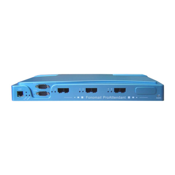
Page 73: The Unit´s Rear Panel
TECHNICAL DESCRIPTION or on flash memory cards (up to a maximum of 3) which are connected to the mother board. • The first 2 ports for basic configuration are found on the mother board. The 4, 6 or 8 port versions are obtained by adding expansion cards, each of which creates 2 further ports. -
Page 74: System Status
TECHNICAL DESCRIPTION LEDs: Power: Power supply indicator / compact flash access activity. Status System status L1 to L8 Line status LAN: Connection and activity Ethernet 9 pin connector Telephone Connector (PC) connectors Power / System Line status C Flash status indicators 9 pin connector (auxiliary) -
Page 75: Appendix - System Messages
APPENDIX Appendix - System Messages $$$1 January $$$10 October $$$11 November $$$12 December $$$2 February $$$3 March $$$4 April $$$5 $$$6 June $$$7 July $$$8 August $$$9 September Monday Monday Tuesday Tuesday Wednesday Wednesday Thursday Thursday Friday Friday Saturday Saturday Sunday Sunday Today... - Page 76 APPENDIX ###8 ###9 AUT_MODE Automatic Mode is active BREAK_MODE Break Mode is active CONFIRM_OPC Press 1 to confirm DATE Current date : DATE_PROMPT Enter 6 digits for the date and 4 digits for the time DAY_MODE Day Mode is active DEL_CONFIRM Press 1 to confirm deletion 2 to cancel it.
- Page 77 APPENDIX 5 to delete NIGHT message 6 to delete BREAK message 0 to select language MOD_ACK Operation accepted MOD_NACK Operation rejected MSG_COUNT Stored messages... MUSIC_ON_HOLD NEW_MSG New messages... NEW_PSW Enter your new password using 4 digits. NIGHT_MODE Night mode is active NO_MORE_MSG No more messages NO_MSG...
- Page 78 APPENDIX MBE_MENU_NOEXT 9 to leave a message in the mailbox 0 to contact the operator UN_MENU Press: 1 to hear the recording of your name 2 to record your name 3 to delete your name 4 to type in the first 3 letters of your name. 5 to remove your name from the ABC Directory.
- Page 79 APPENDIX SUMMER_MODE Summer automatic mode activated MNT_MENU Press 1 for day mode 2 for night mode 3 for break mode 4 for winter automatic mode 5 for summer automatic mode 6 to modify date and time 7 to hear current status 8 to record personalized mailbox messages 9 to record greeting messages for the automatic attendant *(asterisk) to listen to messages from the system mailbox...
-
Page 80: Appendix - Environmental Information
Appendix - Environmental Information Waste Electrical and Electronic Equipment (WEEE Directive) The European Union (EU) Directive on WEEE (waste from electrical and electronic equipment) is intended to protect the quality of the environment and human health through the prudent use of natural resources and the adoption of waste management strategies that focus on recycling and reuse. -
Page 81: Appendix - Rohs Compliancy
Appendix - ROHS Compliancy This stand-alone vocal server complies with the European Parliament and Council Directive on the Restrictions of the Use of Certain Hazardous Substances in Electrical and Electronic Equipment (2002/95/EC). Reference: D227XXJUSTX01EN The manufacturer reserves the right, for the benefit of its customers, to modify the product specifications without prior notice.
Need help?
Do you have a question about the Fonomail ProAttendant and is the answer not in the manual?
Questions and answers