Table of Contents
Advertisement
Quick Links
Advertisement
Table of Contents

Related Manuals for Raytheon SNV-12

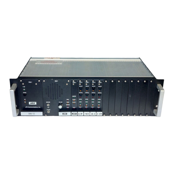
Summary of Contents for Raytheon SNV-12
- Page 1 Installation and Operation Manual SNV-12 Signal-and-Noise Voter Designed and Manufactured by: Raytheon Company 5800 Departure Drive Raleigh, NC 27616 phone: (919) 790-1011 email: voter.sales@raytheon.com P/N 5951-800200 Revision 8.2 March 2009...
- Page 2 PROPRIETARY STATEMENT The information contained in this manual is the property of Raytheon and is intended for the purchaser‟s use only. It may not be reproduced without the expressed written consent of Raytheon. © 2009 Raytheon Company.
-
Page 3: Table Of Contents
SNV-12 Operations Manual Table of Contents OVERVIEW ..............................1-1 ..............................1-1 COPE ............................1-1 ESCRIPTION 1.2.1 General ............................1-1 1.2.2 Card Cage and Backplane ......................1-1 1.2.3 Power Supply Module ........................1-1 1.2.4 Console Interface Module ....................... 1-2 1.2.5 Control Processor Module ......................1-2 1.2.6... - Page 4 3.13.1 Audio Inputs ..........................3-84 3.13.2 Audio Outputs ..........................3-88 3.13.3 Parallel Control Inputs ........................ 3-100 3.13.4 Parallel Control Outputs ......................3-101 SNV-12 OPERATION & TECHNICAL DESCRIPTION ................. 4-1 ..............................4-1 ENERAL ...................... 4-1 ODULAR HASSIS AND ACKPLANE 4.2.1 General ............................4-1 .........................
- Page 5 XPANSION ULTIPLE HASSIS 5.23 AGC ..........................5-29 ILOT 5.24 ....................5-29 ILOT OTCH ILTER ISABLE SNV-12 REMOTE OPERATION........................ 6-1 ..............................6-1 ENERAL ............................6-1 ERIAL .......................... 6-1 EMOTE OMMAND 6.3.1 Manual Site Selection ........................6-2 6.3.2 Site Enable ............................6-3 6.3.3...
- Page 6 SVM Configuration Details ......................6-18 6.5.2 Network Configuration ........................6-18 6.5.3 SVM Status ............................ 6-20 6.5.4 Event Log ............................6-21 6.5.5 SNV-12 Statistics (Counts) ......................6-22 6.5.6 SVN-12 Statistics (Time) ........................ 6-23 OPTIONS ............................... 7-1 PTG-10 P ......................7-1 ILOT ENERATOR APPENDIX ..............................
-
Page 7: List Of Figures
SNV-12 Operations Manual List Of Figures ...................... 2-1 IGURE UICK TART LOCK IAGRAM ........................3-4 IGURE UTLINE IMENSIONS ..................3-5 IGURE ONTROL AND ONNECTOR OCATIONS PSM-1A ........................3-9 IGURE IEW OF , 24 S ..................... 3-25 IGURE XPANSION ABLE YSTEM , 36 S ..................... -
Page 8: List Of Tables
SNV-12 Operations Manual List of Tables 1-1: ..........................1-4 ABLE PECIFICATIONS ..................1-5 ABLE QUIPMENT AND CCESSORIES UPPLIED ................... 1-6 ABLE PTIONAL QUIPMENT UPPLIED ....................3-11 ABLE ASIC NSTALLATION HECKLIST TB1-TB12 S SVM-2 ............ 3-19 ABLE OTER ODULE ONNECTIONS WITH TB1-TB12 S SVM-1 ........... - Page 9 SNV-12 Operations Manual 3-51 SVM J ........................ 3-61 ABLE UMPER ETTINGS 3-52 ......................... 3-63 ABLE UDIO ELAY ETTING 3-53 ..................3-63 ABLE ILOT UARD ELECTION 3-54 COR T ........................3-64 ABLE ELECTION 3-55 TB1-TB12, P 16 C ....................3-65 ABLE...
- Page 10 SNV-12 Operations Manual Glossary Console Interface Module The SNV-12 module that interfaces the voter to a console. Carrier Operated Relay A signal from a receiver that gives a positive indication that a carrier or signal is being received and that the receiver is unsquelched.
- Page 11 Site Voter Module The SNV-12 module that interfaces voting receivers and applies a variety of DSP algorithms to the RX audio input. Transmit or Transmitter...
- Page 12 SNV-12 Operations Manual This page intentionally left blank...
-
Page 13: Overview
1.2 Description 1.2.1 General The SNV-12 will select, from up to 12 individual sites (or 36 in an expanded system), the input with the best signal quality. For FM receivers, the SNV-12 votes based on the noise level present in the received signals. Alternatively, a full Signal-to-Noise Ratio (SNR) calculation works best with AM or HF systems. -
Page 14: Console Interface Module
Master, Expansion 1 Expansion 2. In expanded systems, up to three SNV-12 chassis may be connected together to create a voting system of up to 36 sites. The CPM-3 has an additional LED on the front panel, labeled LINK, to indicate network link status. -
Page 15: Compatibility With Previous-Version Modules
There are three versions: The CIM-1, the CIM-2, and the CIM-2A. All versions are compatible with all other hardware versions of other modules, but to use the current CIM-2A modules in an older chassis, the SNV-12‟s CPM-1 module must have revision 3.37 or higher. All revisions of CPM-3 software are OK. -
Page 16: Specifications
SNV-12 Operations Manual 1.2.8 Specifications Table 1-1: Specifications Site Voter Module RX Audio Inputs & Console TX Audio Input Input Impedance TX Audio (CIM-2) Balanced 600 ohms or unbalanced 50k ohms. Input Impedance RX Audio (SVM-2) Balanced 600 ohms or 10k ohms, or unbalanced 10k ohms. - Page 17 SVM-2 Site Voter Module - P/N 5952-112000 Quantity Item Site Voter Module Plug-in module. As many as 12 Site Voter Modules may be plugged into the SNV-12 Chassis. Unused Site Voter Module slots on the Chassis are covered with blank plates.
-
Page 18: Ptg-10 P Ilot T One G Enerator
To purchase an SNV-12 Signal-To-Noise Voter, order one Chassis and as many Site Voter Modules as desired (one per voting receiver; up to 12 per Chassis). For example, to order an SNV-12 Voter with 5 Site voter Modules, request for one piece P/N 5951-800000 and 5 pieces P/N 5952- 112000. -
Page 19: Field Setup Guide
This Quick Start Guide describes a typical SNV-12 installation with multiple receivers, a single transmitter, and a dispatch console. The SNV-12 voter can be set up for a wide variety of other system configurations; please refer to the manual for advanced capabilities and options. -
Page 20: Basic Installation Instructions
Audio from receiver site 3: use TB3 terminals 1(+) & 2 Audio from receiver site 12: use TB12 terminals 1(+) & 2 Console Connections - The console interfaces the SNV-12 CIM module via rear panel TB13: Console TX audio to voter: use TB13 terminals 1 &... -
Page 21: Module Configuration Sheets
SNV-12 Operations Manual 2.3 Module Configuration Sheets The following sheets are the current “Quick Reference Help Sheets” as of the time of the printing of this manual. A laminated set of the latest sheets is included with this manual. - Page 23 Chassis, Power Supply, and CIM Module SNV-12 Configuration Settings and Adjustments (0=Off, 1=On) Chassis Rear Panel: Designator Factory Setting Switch Choices AC Line Voltage Rear Panel AC Input Module 110 VAC 110 VAC/ 220 VAC (nominal) (Unless Customer Specifies 220 VAC)
- Page 24 CIM Module (continued) SNV-12 Configuration Settings and Adjustments (0=Off, 1=On) CIM Module Configuration: Designator Factory Setting Switch Choices Simplex Mode; Voting Hold Off After TX SW3-2, 3 1 Second SW3-2 SW2-3 Voting Hold Duration 0.5 sec 1.0 sec 1.5 sec...
- Page 25 CPM Module SNV12 Configuration Settings and Adjustments 0=Off, 1=On CPM Configuration Designator Factory Setting Switch Choices Serial Port Baud Rate SW1-1, 2, 3 9600 SW1-1 SW1-2 SW1-3 Baud Rate 1200 2400 4800 9600 19.2K 38.4K 57.6K Serial Port Enable/Disable SW1-4 Disabled 0=Disabled, 1=Enabled Repeat Mode is EIA controlled...
- Page 26 CPM Module (continued) SNV12 Configuration Settings and Adjustments 0=Off, 1=On CPM Configuration Designator Factory Setting Switch Choices Transmit Steering; Hold-Over Timer Setting SW3-1, 2 10 seconds SW3-1 SW3-2 Hold-Over Timer Infinite 3 seconds 10 seconds 30 seconds Voting Locked on Active COR (Also called COR SW3-3 Disabled 0=Voting Lock Disabled (Normal Voting)
- Page 27 SVM Module SNV12 Configuration Settings and Adjustments 0=Off, 1=On Site Voter Module Configuration Designator Factory Setting Switch Choices Receive (Site) Audio Delay 0 ms (No delay) 0=0ms, 1=30ms, 2=60, 3=90, 4=120, 5=150, 6=180, 7=210, 8=240, 9=270, A=300, B=330, C=360, D=390, E=420, F=450ms Pilot Tone/Guard Tone Frequency SW2-1...
- Page 28 SVM Module (continued) SNV12 Configuration Settings and Adjustments 0=Off, 1=On Site Voter Module Configuration Designator Factory Setting Switch Choices RX Group SW3-1, 2, 3 Rx Groups Disabled SW3-1 SW3-2 SW3-3 Group Disabled; Not a member of an RX group RX Group #1 RX Group #2 RX Group #3 RX Group #4...
-
Page 29: Installation
If it is necessary to return the equipment to the manufacturer, a Returned Material Authorization (RMA) number must first be obtained from Raytheon. This number must be noted on the outside of the packing carton and on all accompanying documents. When packing the unit for reshipment, it is best to use the original packaging for the unit;... -
Page 30: Installation Overview
Careful attention to the following installation suggestions should result in the best unit/system performance. Figure 3-1 provides overall unit dimensions. The SNV-12 must be installed in a structure that provides both protection from the weather and assurance of ambient temperatures between -20 and +60 degrees C. Since the unit is neither splash proof nor corrosion resistant, it must be protected from exposure to salt spray. - Page 31 A fully loaded SNV-12 (with twelve SVM modules installed) dissipates approximately 100 watts. Consider other heat sources installed along with the SNV-12 in a 19" rack or other type of cabinet. Do not install other heat generating devices below the SNV-12. Use forced air-cooling in the cabinet if necessary.
- Page 32 SNV-12 Operations Manual SNV-12 Figure 3-1 Outline Dimensions...
-
Page 33: Rear View
SNV-12 Operations Manual REAR VIEW TB13 AC INPUT SCREW-TERMINAL CONNECTIONS PULL TO AC INPUT FOR FIRST 115/230 VAC CHANGE FUSE VOTER MODULE ± 15% SPARE FUSE 47 TO 63 Hz INSIDE 1.2/0.6 AMPS DISCONNECT BOTH SIMILAR AC AND DC CABLES... -
Page 34: Power Requirements
SNV-12 is currently using. 3.6.1 AC Voltage The SNV-12 is designed to operate from 115V or 230V, 47 to 63 Hz, single-phase AC power source. The unit will meet all of its specifications over a voltage range of +/- 15% from nominal. -
Page 35: Dc Voltage
3.6.2.2 Battery Power for the SNV-12 The SNV-12 may also be connected to a 12V battery to provide back-up power if the AC mains fail. When powered by a +12V battery at the DC input, the SNV-12 current consumption is the following: 0.46A + (0.37A * # SVM). -
Page 36: Fuse Information
In addition, for batteries sized to provide more than one hour of backup, chargers will have to be provided, as the charger built into the SNV-12 can only supply 1 A, so it would take too long to recharge the batteries necessary for an 8 HR backup time. - Page 37 SNV-12 Operations Manual Figure 3-3 Side View of PSM-1A This is a simplified side view of the PSM-1A. To replace Bus Voltage Fuse F1, first turn off the Main Power pushbutton and remove main power cabling from the unit. Loosen the four captive front panel screws and carefully slide the PSM-1A from the chassis.
-
Page 38: Grounding Considerations
All wire line circuits (leased-line circuits, private circuits, etc.) should go through surge protection prior to connection to the SNV-12. This device should meet or exceed the specifications of a Polyphasor model IS-DPTL and should be connected to a site single- point ground system. -
Page 39: Installation Checklist
SNV-12 Operations Manual 3.9 Installation Checklist Table 3-1 Basic Installation Checklist Provide suitable Mounting and Cooling. See Section 3.4 Check AC Line voltage selection. See Section 3.6.1 DC Operation needed? See Section 3.6.2 Battery Backup needed? See Section 3.6.2 Make Interconnections. - Page 40 SNV-12 Operations Manual Table 3-1 Basic Installation Checklist Is Automatic TX Steering (STARS) Enable STARS on the CPM SW2-7. Set needed? Holdover Timer with CPM SW3-1, 2. See 3.12.5.2, 3.12.5.3, 5.13, 5.17 and 5.19. Should Console and Repeat Audio Change the Default TX Site selection to Multicast Transmissions be multicast to all sites with CPM SW1-8.
-
Page 41: Audio Links
SNV-12 Operations Manual 3.10 Audio Links The receive and transmit audio for each SVM must be linked to its associated receiver and/or transmitter. If the voter is co-located with the console and RF equipment, local wiring can be used. However, if the voter is separated from the other equipment geographically, other means of sending audio, COR and PTT must be considered. -
Page 42: Wireline Links
SNV-12 Operations Manual 3.10.2.2 Use Of COR Signal From The Link Receiver With this configuration, the link transmitter detects COR from the voted receiver, then keys up and retransmits the receiver‟s audio. The link receiver (co-located with the voter) unsquelches and provides a hardwired COR signal to the SVM. - Page 43 SNV-12 Operations Manual If a standard voice grade line is requested, the following will normally result: Loss at 1000 Hz will be between 5 and 10 dB. Long term variation 4 dB. Frequency response referenced to 1000 Hz: 300-3000 Hz: +3 to -12 dB.
-
Page 44: Satellite Links
3.10.5 Network Links The use of the Internet Protocol (IP) to link remote voting receiver audio back to the SNV-12 is strongly discouraged and we will not attempt to assist installations that use IP links. - Page 45 SNV-12 Operations Manual The addition of VoIP devices carries many additional timing problems. Again remember that an analog voter needs near-identical timing on all paths between voting receivers & the voter. Typical VoIP communications do not share this concern and hence do not have methods to maintain the relative timing between the various paths.
-
Page 46: External Interconnect Information
DC input voltage (+V) are clearly marked. 3.11.2 Site Voter Module Connections Each of the SNV-12 Site Voter Modules has an associated 20-pin screw terminal block. The pin connections for each site are identical. The connectors are labeled J1-J12 on the terminal block backplane, for Site Voter Modules 1 through 12. - Page 47 SNV-12 Operations Manual Table 3-2 TB1-TB12 Site Voter Module Connections with SVM-2 Signal Description Site Audio In A Balanced or unbalanced audio input from the site receiver. (See note 1 below) Site Audio In B Other half of balanced audio input pair from the site receiver.
- Page 48 SNV-12 Operations Manual Table 3-3 provides the TB1-TB12 interface description when the SVM-1 module is installed. The pins that have some differences are: 1 & 2 now have balanced / unbalanced jumper with SVM-2. 9 & 10 new functions with SVM-2 13 &...
-
Page 49: Serial Remote Connector
SNV-12 Operations Manual 3.11.3 Serial Remote Connector This female 9-pin D-sub connector provides a serial RS-232 interface. The connector is labeled P1 on the backplane. Standard DCE pinout is used: P1 – Serial Remote Connections Table 3-4 Signal TX Data... -
Page 50: Console Interface Connections - P2
SNV-12 Operations Manual 3.11.4 Console Interface Connections – P2 This connector carries control signals and audio between the console and the voter chassis. Most of the more important connections are also found on the 18 pin terminal block, TB13, (Not found on some earlier hardware versions). See Table 3-5. The P2 and TB13 connections are direct parallel connections, so only one or the other may be used for any particular signal without consideration for double-terminations. -
Page 51: Console Interface Connections - Tb13
SNV-12 Operations Manual 3.11.5 Console Interface Connections – TB13 This connector, like P2, carries control signals and audio between the console and the voter chassis. Some of these signals have direct parallel connections on P2, so only one or the other may be used for any particular signal without consideration for double-terminations. -
Page 52: Expansion Connector
SNV-12 Operations Manual 3.11.6 Expansion Connector In an expanded voter system consisting of more than one chassis, this connector is cabled to the Console Connector in the next chassis in the system. In the final voter (Expansion shelf 2 in a three chassis system, Expansion shelf 1 for two chassis) in a system, this connector is not used. - Page 53 SNV-12 Operations Manual Figure 3-4 Expansion Cable, 24 Site System 3-25...
- Page 54 SNV-12 Operations Manual Figure 3-5 Expansion Cable, 36 Site System 3-26...
-
Page 55: Module Configuration Settings And Adjustments
SNV-12 Operations Manual 3.12 Module Configuration Settings and Adjustments This section explains the level adjustments and configuration switch settings for all SNV-12 modules. To access the potentiometers, jumpers and switches, use the Extender Card found in the Accessory Kit. Remove the module to be adjusted and install the extender card in its place. -
Page 56: Cim-2A Console Interface Module
SNV-12 Operations Manual 3.12.2 CIM-2A Console Interface Module The CIM-2A module interfaces Voted Audio Output to, & TX Audio Input from, a console. A Digital Signal Processor on the module provides TX audio delay capability, detects keying tones in the Console TX input and adds keying tones to the TX output audio that‟s available at the SVM TX audio outputs. - Page 57 SNV-12 Operations Manual AUDIO DELAY PEAK NORM REMOTE FAULT CIM-1 NORM INT SPKR EXT SPKR NORM VOTED UNBAL VA MUTE CONS TX INPUT AUDIO DELAY CIM-2 NOTE: NO JP3-JP7 ON SOME EARLIER REVISION MODULES UNBAL SPEAKER VOLUME ACT LO JP7 VA MUTE...
- Page 58 SNV-12 Operations Manual 3.12.2.1 CIM Jumper Configuration The jumpers on the CIM module are listed on Table 3-10 and shown on Figure 2-6. Table 3-10 CIM Jumper Settings Jumper Function Pos 1&2 Pos 2&3 Speaker: Internal or External Internal *...
- Page 59 Up to 50 ms delay is required to interpret all inputs for correct PTT and audio routing in a full 12 site single chassis SNV-12. This control signal delay is a result of the need for the CPM module, after it receives a request to key, to poll all of the SVMs to see if any TX Inhibit or Manual TX Steering inputs are currently active.
- Page 60 SW2-1, 2, and 3- Transmitter Control; Keying Tone Frequency & Type The SNV-12 can generate various key tones and mix them with the SVM TX audio outputs. The voter can also detect the EIA key tone sequence in the Console TX Input audio. The available single-tone keying tones are 1950 Hz, 2175 Hz, 2600 Hz, and 2950 Hz.
- Page 61 The tone detected determines which SVMs are keyed. See Section 5.20 for additional information. When standard EIA key tone detection is enabled, the SNV-12 may be switched remotely in and out of the repeat mode by sending the proper function tone via the console TX audio input.
- Page 62 SNV-12 Operations Manual Alternate EIA Function Tone Selection The voter can generate any one of four different function tones. The standard function tone is F1, 1950 Hz. The alternate tones are selected via rear panel outputs (rather than internal dip switches) to allow them to be dynamically selected during operation.
- Page 63 TX mode as long as the low level guard tone (hold tone) is present. Beginning with Rev 4.0 SNV-12 software, the EIA Function Tone Enable feature will also allow the Repeat Mode to be turned off and on by sending the proper EIA sequence in the Console TX Audio (high guard followed by the proper function tone, no low guard tone).
- Page 64 SNV-12 Operations Manual SW2-7 Site Unsquelch Time Limiter This feature faults any site that remains continuously unsquelched for more than 3 minutes. This was intended to benefit systems where a continuous radio link brings the remote receiver audio to the voter. The purpose is to remove from consideration for voting sites that become...
- Page 65 RX frequency. It‟s also important that the SNV-12 does not vote for a short time following the end of each console transmission, so that the unit does not vote a squelch tail that might be present following the transmission.
- Page 66 (either due to console TX activity or by the retransmission of voted audio.) COR. Low (and relay energized) when any one of the SNV-12‟s sites is unsquelched. Please note that this indication occurs only following the CPM polling and computation process, and therefore is not instantaneous.
- Page 67 When SW3-8 is on, console TX transmissions will have the same hangtime duration as Repeat Mode transmissions (as set by CIM SW3-4, 5). If the SNV-12 is set to Console Priority rather than Field Priority (CIM SW3-1), the Console Priority status is overruled during the hangtime period, allowing repeat mode retransmission of voted audio to occur during this time.
- Page 68 (CIM SW3-1 Off). The SNV-12 must also be in the Repeat Mode (CPM SW3-7). The retransmitted field audio that‟s mixed with the console audio can be attenuated three different amounts: 6 dB lower, 3 dB lower, 0 dB.
- Page 69 SNV-12 Operations Manual SW4-4 Console PTT Input Polarity The Console PTT Input normally requires an active low input. If SW4-4 is set to ON, an active high input is required to put the voter into the TX mode. Note that, because of the pull-up resistors in the CIM module, the voter will be placed in a constantly keyed state if the PTT input line becomes an open-circuit.
- Page 70 SNV-12 Operations Manual SW4-6 TB13-12 Alternate Function – STARS Enable Input (For use with CPM-3 and CIM-2A Only) Switching SW4-6 ON re-assigns the TB13-12 input to be a STARS Enable/Disable input rather than Directed Unsquelch Input. The input is active low with a pull-up resistor. When the input is asserted (driven low), the STARS function in the voter is enabled.
- Page 71 SNV-12 Operations Manual 3.12.2.6 CIM Audio Level Adjustment As shipped from the factory, the input and output levels of each Console Interface Module (CIM) module are set to -10 dBm. If level requirements differ, the Console TX Audio Input level may be adjusted via potentiometer R50, (available through an access hole in the front panel on the CIM-2, and on the CIM-1 near the top center of the board).
- Page 72 SNV-12 Operations Manual Transmiter Tx Audio Tx Audio Console Receiver Rx Audio Rx Audio TB-13 TB-1 thru 12 Console Interface Site Voter Module (CIM) Module (SVM) Repeat Enable Tx Bus Rx Bus Back Plane Figure 3-7 Audio Routing The following procedure sets the level of the CIM‟s Voted Audio Output to the console.
-
Page 73: Control Processor Module
SNV-12 Operations Manual 3.12.3 CPM-3 Control Processor Module The SNV-12 CPM module uses 3 banks of 8-position dipswitches along with a 16-position rotary switch to set its operating parameters. These switches are read by the CPM only during unit power-up. To change any parameters, turn off the unit, remove the CPM-3 card and adjust the positions of SW1 through SW4 as desired, re-insert the module, and turn main power back on. -
Page 74: Real Time Clock (Rtc)
SNV-12 Operations Manual 3.12.5 Real Time Clock (RTC) The CPM-3‟s RTC clock will maintain the set time in the event of a power outage. The unit is not shipped with a battery. If RTC operation is desired, purchase and install a 3V CR2032 type lithium battery in the battery holder. - Page 75 SNV-12 Operations Manual 3-47...
- Page 76 SW1- 5 Control of Repeat Mode Using EIA Keying Tones The SNV-12 can use the detection of EIA keying tones in the Console TX audio (if CIM SW2- 6 is On) to control transmitter keying and the current state of the Repeat Mode Feature. If there is no intention to turn Repeat Mode off and on using function tones, leave SW1-5 On.
- Page 77 Section 4.15. The factory default destination is to the Home Site. Multicast refers to all TX eligible sites. Home Site refers to one site only, the lowest-numbered TX eligible site. See Section 5.13, SNV-12 Transmit Features, for more in-depth information. 3-49...
- Page 78 SNV-12 Operations Manual Table 3-35 Default TX Site Selection SW1-8 Default TX Destination Home Site * Multicast 3-50...
- Page 79 SNV-12 Operations Manual 3.12.5.2 CPM Switch SW2 Settings NOTE- Factory settings are marked *. SW2- 1, 2, and 3 Voting Criteria; Signal Quality These switches determine the signal quality difference that must be exceeded before one SVM is voted over another. If site "A" is presently voted, site "B" must maintain a better signal than site "A"...
- Page 80 This switch enables the STARS (Smart Transmit And Receive Steering) function. STARS is the SNV-12‟s automatic TX Steering feature; it allows the transmit site to be chosen based on which receive site was voted best during the last portion of the received transmission. This is not necessarily the site that was voted last.
- Page 81 SNV-12 Operations Manual NOTE: Once the CPM has finished updating the CPLD and all of the modules, this dipswitch must be turned back to off, or the SNV-12 will again update all module software every time the power is cycled.
- Page 82 As long as this site retains COR (whether a hard-wired COR input or the absence of pilot tone, it will be the voted site. When the voted and locked site loses COR, the SNV-12 is free to vote again. As soon as another site is voted, it will be locked as long as its COR signal remains active.
- Page 83 Simplex (Half-Duplex). In a duplex system, transmit and receive frequencies are different. There are also separate paths for TX and RX audio between the SNV-12 and the station. When set to Duplex, the voter can simultaneous vote receive sites and transmit console TX audio.
- Page 84 SNV-12 Operations Manual SW3-7 Repeat Mode This switch is used to enable Repeat Mode operation. When this feature is enabled, voted audio is both sent to the console and retransmitted to the field. See Sections 5.15 through 5.21 for a full explanation of the various voted audio retransmission modes and operational features available.
- Page 85 S4 determines the time that one site must exhibit a better SNR or noise level than the presently voted site before the SNV-12 will change the voted site. If site "A" is presently voted, site "B" must maintain a better signal than site "A" by the amount set by the CPM switches SW2-1, 2, 3 for the entire duration of the time set by SW4 in order to be voted over site "A".
- Page 86 COR Lock may take a longer (but not shorter) period of time than the SW4 setting because of the polling operation of the SNV-12. The CPM communicates with each SVM in turn, so the precise timing depends on a module‟s order in the polling cycle and the number of SVMs in the system.
-
Page 87: Svm Site Voter Module
SNV-12 Operations Manual 3.12.6 SVM Site Voter Module The SVM interfaces the SNV-12 with each voting site. The SVM‟s Digital Signal Processor performs a variety of functions including Signal Quality measurement, pilot tone detection and notching, speech detection, and RX audio delay. The configuration of these functions and others are explained in this section. - Page 88 SNV-12 Operations Manual Table 3-50 Site Voter Module Switch Assignments Switch SW1 RX Audio Delay Switch SW2 Function Pilot Tone Frequency COR Type COR Type Guard Tone Enable COR Threshold -OR- Pin 16 Configuration TX Sel Out or Unsquelched Out...
- Page 89 SNV-12 Operations Manual Special Notes Regarding SVM Dipswitch Assignments The switches SW2-5 and SW2-6 set the audio derived COR threshold only if SW2-2 and SW2- 3 are both on, configuring the SVM to the Audio Derived COR type. If SW2-2 and SW2-3 set the SVM for either Pilot Tone or Hardwired COR, SW2-5 and SW2-6 instead fill the other function listed in the table.
- Page 90 SNV-12 Operations Manual JP3 COR Input Configuration The options are NORM (JP3 on pos 1&2) or E&M (JP3 on pos 2&3). When set to NORM, the SVM expects a logic level signal to indicate the active COR (receiver unsquelched) condition.
- Page 91 SNV-12 Operations Manual 3.12.6.2 SVM Switch SW1, Receive Site Audio Delay NOTE- Factory settings are marked *. SW1 is a BCD rotary switch used to set the desired amount of RX audio delay through the Site Voter Module. The amount of delay is adjustable from 0 to 450 milliseconds in 30 msec steps.
- Page 92 SNV-12 Operations Manual SW2-2, 3 COR Type The type of COR (voting receiver unsquelched condition indication) selection in use by each SVM and its associated receiver is set by SW2-2 and SW2-3. See also Sections 5.10 and 5.11. Table 3-54...
- Page 93 SW2-5, 6 Audio Level COR Threshold The SNV-12 Site Voter Module can be set to generate its own internal COR based on the input receiver audio level. (See Section 5.10 and SW2-2, 3 COR Type above.) This feature is not for installations where either a hardwired COR line or a pilot tone is available;...
- Page 94 SNV-12 Operations Manual When there is not a sufficient increase in noise between the squelched and unsquelched receiver audio to operate as described above (usually due to a noisy line), the SVM can instead indicate an unsquelched condition when it detects actual speech in the receiver audio. Set the thresholds so that the UNSQ LED lights whenever there is speech in the received signal, but it‟s out when no speech is present.
- Page 95 NOTE: If an active high COR polarity is selected, but no connection is made to the SVM COR input, the SNV-12 will assume that COR is active. This is due to a pull-up resistor in the SVM module’s COR Input circuit.
- Page 96 Each SNV-12 Site Voter Module can be set up to be associated with a receiver group. An SNV-12 can have up to 7 RX groups. A “Group 0” designation means the site is not part of any group. See Sections 5.13 through 5.20 for a complete discussion of RX groups and the various ways that they can be used.
- Page 97 SNV-12 Operations Manual Table 3-61 Function Tone Guided TX Steering Selection SW3-1 SW3-2 SW3-3 Function Tone Not Keyed by Any Function Tone * Group 1 -1950 Hz Group 2 -1850 Hz. Group 3 -1350 Hz. Group 4 -1250 Hz. Group 5 -1150 Hz.
- Page 98 AM/HF mode SW3-6 Simplex Repeat To Currently Voted Site When in the Simplex Mode and the Repeat Mode, the SNV-12 normally will not send repeat audio and keying commands to the voted site. This prevents the keying of a simplex transceiver at the voted site, as keying would take the unit out of its RX mode, making it ineligible for voting and setting up a feedback loop of voting, keying, un-voting, unkeying, voting, etc.
- Page 99 If a transmitter is picked up by a group of receivers that send the audio back to the SNV-12 by a mixture of these two methods, both microwave and actual wires, there may be a bias created in favor of voting the leased line sites (due to the lower amount of noise that reaches the SNV-12 from these receivers).
- Page 100 SNV-12 Operations Manual Equalization is likely to be required for installations that mix leased line and microwave links. In this case, the frequency response of either the leased line or one of the receivers may be the cause. It may also be useful to try the lower levels of equalization for leased line only installations where a site with poorer audio quality is being voted over a better-sounding site that is also unsquelched.
- Page 101 This AGC is intended to compensate for level changes in the link between each remote receiver site and the SNV-12. It is not intended to compensate the different volume levels of different system users. The AGC tracks the level of the pilot tone input; if it changes, the SVM‟s internal DSP gain is changed to compensate.
- Page 102 Ideally, the link between the remote receiver and the SNV-12 has a flat frequency response from 300 to 3k Hz. If the pilot tone and the received speech (simulated by a 1 kHz test tone) leave the receiver at the same level, high-frequency roll-off can cause the pilot tone to be at a relatively lower level when measured at the SVM audio input pins.
- Page 103 SNV-12 Operations Manual For example, if the RX level at the receiver is -10 dBm and the pilot tone is -13 dBm, and at the voter they measure -9 and -14 respectively, the relative pilot tone level is -2 dBm.
- Page 104 SNV-12 Operations Manual When the filter is disabled, the SVM does not run its DSP notch filter algorithm even when set for Pilot Tone COR. The SVM cannot squelch until it detects a pilot tone, and some time is required to detect this tone, so it will be momentarily present in the voted audio output (and, when Repeat Mode is used, in the retransmitted voted audio).
- Page 105 SNV-12 Operations Manual SW5-4 COR Delayed with Receive Audio When RX audio delay is added using an SVM‟s rotary switch SW1, the COR (unsquelched) indication can either be reported immediately or delayed along with the RX audio. When not delayed, the audio delay is used to compensate for other system delays so that the site is voted and repeaters keyed, etc., before the audio is passed through the system.
- Page 106 Audio Delay function is meant as a secondary option for the case when modifying the radio system is not possible. NOTE: To properly configure the SNV-12 the RX Output Audio Delay should first be set to disabled. Next, the RX Site Audio Delay (SW1) should be used to compensate for line delays between the receiver and the SVM modules.
- Page 107 Press the module‟s SELECT pushbutton to force-vote the site so you can listen on the SNV-12 speaker. When the RX level control is adjusted properly, the NORM LED on the SVM will be lit on normal audio levels.
- Page 108 SNV-12 Operations Manual Set the SVM‟s receive audio level pot (R45) so that the average voice (1kHz tone) just lights the NORM LED (Yellow). Verify this adjustment by connecting a transmission test set to test points 3 (TP3) and ground. The SVM-2 should be set for 5dBm and the SVM-1 should be set for 0dBm.
- Page 109 SNV-12 Operations Manual SNV-12 Voter to Site Alignment Diagram Site Voter Module (SVM) -Set the SVM receive audio level pot (R45), so that the average voice (1KHz tone) just lights the NORM LED. -Connect a transmission test set to the -Verify this adjustment, by connecting a receiverÕ...
-
Page 110: Expanded Voter System Alignment
3. With the service monitor still producing a 1kHz signal at the receive site, verify the audio level measured at the associated SNV-12 terminal block (pins 2 & 1). It must measure between -30 to +10dBm. 4. Set the SVM‟s receive audio input potentiometer (R45) so that the 1kHz average voice test tone just lights the NORM LED (Yellow). - Page 111 SNV-12 Operations Manual 10. Using a tone box, generate a 1kHz tone into the console‟s microphone, at a level that will produce a 100% modulation. (Some consoles produce a test tone that can be used during alignment) The 1kHz tone is used to simulate average voice (Test Tone).
-
Page 112: I/O Descriptions
SNV-12 Operations Manual 3.13 I/O DESCRIPTIONS This section provides detailed explanations and schematics of the SNV-12‟s audio interfaces and its parallel control inputs and outputs. 3.13.1 Audio Inputs The audio input of the CIM-1 Console Interface is 600 ohm balanced, and Site Voter Module input may either be 600 ohm or 10k ohm balanced. - Page 113 SNV-12 Operations Manual Figure 3-12 SVM-1 Remote Receiver Audio Input 3-85...
- Page 114 SNV-12 Operations Manual Figure 3-13 CIM-1 Console TX Audio Input The CIM-1 input is 600 ohm, balanced. No jumper is supplied to create an unbalanced or high impedance input. To connect to an unbalance output, ground Console TX Input B, and wire the single-ended console audio input to Console TX Input A.
- Page 115 SNV-12 Operations Manual Figure 3-14 CIM-2 Console TX Audio Input On the CIM-2 module, Jumper JP2 allows either a 600 ohm balanced input or a high impedance single-ended input. 3-87...
-
Page 116: Audio Outputs
SNV-12 Operations Manual 3.13.2 Audio Outputs All audio outputs are 600 ohm balanced, but may be set to 600 ohm unbalanced by grounding the unused output terminal. For 600 ohm unbalanced, ground the Audio Output B terminal to the Audio Ground Terminal and use the Audio Out A terminal as the signal source. The use of balanced outputs and shielded cables are recommended for superior immunity to noise. - Page 117 SNV-12 Operations Manual E&M Interfaces Figure 3-17 SVM-2 COR / E&M Input When the jumper is in the “Norm” position, a 2.5 VDC (nominal) threshold signals active COR. Active low is standard; a dipswitch on the SVM module changes operation to active high.
- Page 118 SNV-12 Operations Manual Figure 3-18 SVM-2 PTT / E&M Output When JP4 is in the Norm position, the PTT output is an open-collector transistor with a 470 ohm pull-up resistor. When this jumper is moved to the E&M position, the PTT output is now connected to the common terminal of a relay.
- Page 119 SNV-12 Operations Manual Table 3-74 E & M Lead Chart E Lead E Lead M Lead M Lead Idle Busy Idle Busy Type I Open Ground Ground Battery Type II Open Signal Ground Open Signal Battery Type III Open Ground...
- Page 120 SNV-12 Operations Manual Figure 3-19 SVM-2 for Type I Signaling 3-92...
- Page 121 SNV-12 Operations Manual Figure 3-20 SVM-2 for Type II Signaling 3-93...
- Page 122 SNV-12 Operations Manual Figure 3-21 SVM-2 for Type III Signaling 3-94...
- Page 123 SNV-12 Operations Manual Figure 3-22 SVM-2 for Type V Signaling 3-95...
- Page 124 SNV-12 Operations Manual The following diagrams illustrate how to connect E & M leads to a CIM-2 module for type I, II, III and V signaling: Figure 3-23 CIM-2 for Type I Signaling 3-96...
- Page 125 SNV-12 Operations Manual Figure 3-24 CIM-2 for Type II Signaling 3-97...
- Page 126 SNV-12 Operations Manual Figure 3-25 CIM-2 for Type III Signaling 3-98...
- Page 127 SNV-12 Operations Manual Figure 3-26 CIM-2 for Type V Signaling 3-99...
-
Page 128: Parallel Control Inputs
SNV-12 Operations Manual 3.13.3 Parallel Control Inputs The following applies to all parallel control inputs of all SNV-12 modules. See the schematic representation below. The inputs are held up to +5 VDC; when this input is pulled below an approximately +2.5 VDC threshold, the input is considered active, and the internal signal goes high. -
Page 129: Parallel Control Outputs
SNV-12 Operations Manual 3.13.4 Parallel Control Outputs The following applies to all SNV-12 parallel control outputs. See the schematic representations below. When an output becomes active, the open-drain transistor is turned on; current flows through the transistor drain to ground, pulling the output low. The maximum voltage that can be applied to the drain of the transistor at the output connection is +60 VDC. -
Page 131: Operation & Technical Description
The modules can only function correctly when plugged into the correct type of slot, but the SNV-12 is designed so that modules will not be harmed when plugged into incorrect slots. The Power Supply card edge connector is offset so no other modules can be plugged into it. -
Page 132: Power Supply Module
SNV-12 Operations Manual CIM-2A CPM-3 PSM-1A SVM-2 SVM-2 SVM-2 VOLUME LINK TX SEL TX SEL TX SEL +12V SELECT SELECT SELECT -12V SPEAKER NORM NORM NORM RX+TX ETHERNET DISABLE DISABLE DISABLE POWER RX IN RX IN RX IN VOTED OUT... -
Page 133: And -12V Indicators (Psm-1)
SNV-12 Operations Manual 4.3.5 +12V and -12V Indicators (PSM-1) These green LEDs are driven from the corresponding power supply output voltages and are illuminated whenever the unit's main power is on. A dark LED when the AC or DC indicators are on could indicate a failed power supply voltage. -
Page 134: Control Processor Module (Cpm)
Master CPM Controls Expansion CPMs In Expanded Systems 4.5.2 General The unit's CPM Module controls the entire SNV-12. Via an internal high-speed serial bus, it requests and receives SNR, Signal Quality, COR (signal present), speech present, and other information from each Site Voter Module and votes the SVM with the best signal. It instructs this SVM to output its audio to the voted audio bus. -
Page 135: Fault Led
SNV-12 Operations Manual The system uses a similar scheme to share information between multiple chassis in a Master/Expansion system. If a voter is configured as an "Expansion Chassis", it will read all the Signal Quality information for each of its modules. It then calculates the "Best Signal Quality Available"... -
Page 136: Site Voter (Svm) Module
Module from the Console Interface Module. Transmit and receive audio are extended to additional SNV-12s when site expansion (past 12 SVMs) is required. The SNV-12 votes audio, no matter what its source. The site receiver link to the SVM Modules may be leased lines, hard wire, or E&M pairs. -
Page 137: Software Description
SNV-12 Operations Manual 4.6.4 Software Description The Site Voter Module software is contained in flash memory and can be updated by the CPM module whenever software changes are necessary. The SVM Module Flash is partitioned into sectors. Bootloader code is programmed into one sector that is protected to prevent accidental erasure. -
Page 138: Rx Input Level Indication Leds, Test Point And Adjustment Potentiometer
SNV-12 Operations Manual 4.6.7 RX Input Level Indication LEDs, Test Point and Adjustment Potentiometer Two RX level indication LEDs, along with the RX level adjustment potentiometer, are available through a window in the SVM-2 front panel. When the RX input is properly set, the green “normal”... -
Page 139: Rear Panel Connectors
SNV-12 has already been correctly configured per Section 3. 4.8.1 Unit Power-Up Prior to initial power-up, ensure the SNV-12 is correctly configured for the AC or DC power source being used. If using 230 VAC, make sure the unit is not configured for 115 VAC, or damage may result. -
Page 140: Voting Controls
4.9 Remote Control The SNV-12 may be controlled and monitored remotely via its serial command interface (RS- 232 or Telnet) or the web based user interface (see Sections 3.11.3 and 6). As many as three SNV-12s may be connected together to create a voting system of up to 36 sites. -
Page 141: Manual Tx Selection
All of the SNV-12 Modules, except the PSM power supply module, can be "Hot-Plugged"; that is, they can be removed and inserted while the unit's main power is on and the unit is operational without any damage resulting. - Page 142 SNV-12 Operations Manual End of Section 4 4-12...
-
Page 143: Features And Capabilities
SNV-12 Operations Manual 5 Features and Capabilities 5.1 General This section explains the features and capabilities of the SNV-12. See 8.2 for a list of features supported in various software versions, beginning with revision 2.50. The software or hardware installed in your SNV-12 may not support some features listed. -
Page 144: Voting Transition Criteria
To set the SNV-12 to vote based on SNR (AM/HF mode), a dipswitch must be set on each SVM. Note: All SVMs in a chassis must be set for the same mode; there cannot be a mixture of FM and AM/HF settings on the modules. - Page 145 SNV-12 Operations Manual Figure 5-1 RX Audio Delay...
-
Page 146: A- Standard Voting With No Audio Delay
The UNSQ IN signal denotes the state of the COR input (or pilot tone detect function). The Vote Out control signal shows the time when audio is available at the SNV-12 Voted Audio Output port. Voted Out represents this audio signal. -
Page 147: Voting Lock (Cor Lock)
12 is free to vote again. See Section 2.9.3.3. CPM SW4 can be used to set the amount of time that SNV-12 will wait, following the initial detection of an unsquelched SVM, before the Voting Lock is put into place. See 3.12.5.4. -
Page 148: Receiver With Hardwired Cor Signal
Its Unsquelched LED will always be lit. If all SVMs use this COR type, all SVM Unsquelched LEDs are lit at all times, and the SNV-12 votes one of these sites based on the best signal quality measured among all sites, even when no receivers are unsquelched. Other... -
Page 149: Audio Level Cor With A Squelched Receiver
If a COR output signal is available from the receiver, either Hardwired COR or pilot tone generators should be used. If it‟s impossible to attain a COR signal, the SNV-12 can use a sensitive level-detecting algorithm to allow operation with squelched receivers. This mode will not work well if there is a requirement for repeated voted audio and also may not function well for some systems due to variations in noise levels. -
Page 150: Line Fault (Pilot Tone Fault/Cor Fault) Detection
The site becomes eligible again as soon as guard tone is again detected. The SNV-12 automatically notches the guard tone out of the received audio so it is neither heard by the console nor re- transmitted. -
Page 151: Transmit Features
SNV-12 Operations Manual 5.13 SNV-12 Transmit Features The following is a quick overview of SNV-12 features related to the use of transmitters in a voting system. All features are discussed more fully in subsequent Sections. This overview introduces the basic concepts and definitions that follow and facilitates their understanding. -
Page 152: Receive Only Sites
Default TX Sites: Home Site or Multicast (see Section 5.16). Other SNV-12 configuration options affect the SVMs that will retransmit voted audio: Duplex Mode/Simplex Mode: When the system is set to Simplex Mode, voted audio will not be retransmitted to the voted site. -
Page 153: Repeat Mode And Automatic Transmit Steering
See Sections 5.19.4 and 3.12.2.4. 5.15.2 Repeat Mode and Automatic Transmit Steering The SNV-12 has two automatic TX steering options: STARS and RX Groups. See details for each in their associated sections. STARS does not affect Repeat Mode TX steering. -
Page 154: Default Transmit Site Selection
Repeat Mode voted audio retransmissions are sent via the Home Site only. The Home Site is the lowest-numbered SVM in the SNV-12 voting system that is TX eligible. The Home Site transmitter is usually a general-coverage broadcast transmitter. -
Page 155: Holdover Timer
SNV-12 Operations Manual NOTE- When the Default Transmit Site Selection is the “Home Site”, the home site should be a general coverage transmitter that will provide adequate RF coverage in the required service area. When multicast is used, attention should be paid to prevent the possibility of simulcast overlap problems. -
Page 156: Holdover Timer With Momentary Manual Tx Steering
SNV-12 Operations Manual 5.17.2 Holdover Timer With Momentary Manual TX Steering The Holdover Timer is also active when TX steering selections are made via the MOM TX SEL input on the SVM‟s rear panel terminal block or by the RS-232 MOM_TXSEL command. -
Page 157: Receiver / Transmitter Groups
SNV-12 Operations Manual Mom TX, multiple sites: Start with no activity. The TX SEL site is the Default TX Site. A site is selected by Mom TX as the TX SEL site. The holdover timer starts running as soon as it‟s invoked. When it runs out, the TX SEL site designation returns to the Default TX site. -
Page 158: Group Operation And Repeat Mode
The SNV-12 can be set to provide automatic routing of console transmit audio and keying signals to the proper transmitter site. -
Page 159: Automatic Tx Steering Related To Rx Group Designations
The SNV-12 detects the absence of pilot tone at these three receivers, making all three eligible for voting. The voter‟s signal quality measurements show that site #1 is a bit better than site #2, and site #3, which is far away, has a barely intelligible signal. -
Page 160: Manual Transmit Steering
SNV-12 Operations Manual 5.19.3 Manual Transmit Steering The dispatcher can manually select which sites‟ transmitter(s) will be used for console and repeat transmissions. This manual selection will override the Default TX Site selection, RX Group designations, Group Lockout with Primary Site Failure, and STARS. It cannot be used to transmit from an SVM that has been designated as RX Only. - Page 161 SNV-12 Operations Manual 5.19.3.3 Momentary TX SEL IN of SVM If a momentary logic low is provided to the SVM‟s rear panel MOM TX SEL IN input, console and repeat transmissions will be routed to the selected site for the duration of the Holdover Timer or until another site is selected.
-
Page 162: Console / Field Transmit Priority
SNV-12 Operations Manual 5.19.4 Console / Field Transmit Priority The voter can be set up so that either the presence of an active Console PTT has priority, or the fact that any site is voted takes priority (field priority). When the voter is in the Duplex and Repeat Modes, this priority selection decides which audio source will be transmitted whenever these two conditions occur simultaneously. -
Page 163: Transmit Site Selection Indication
For example, when the SNV-12 is set for Simplex Repeat operation, multicast console audio is transmitted via all sites, while voted audio is retransmitted via all sites except the voted site. - Page 164 Repeat Mode off, STARS and RX Groups off, Default TX Site is Multicast. When the SNV-12 is first powered up, TX Select LEDs of all SVM-2s will be lit (and the Select LEDs of all SVM-1s will flash… the remainder of this explanation will assume that SVM-2s are installed, but the SVM-1 would function identically with flashing Select LEDs instead of individual TX Select LEDs).
-
Page 165: Vote Indication Hold After Squelch
Go back to the fully factory-default voter, with one exception: The Default TX Site is changed from Multicast to Home Site. When initially powered up, the SNV-12 will light the TX Select LED(s) of the Default TX site. Since the Default Site selection is now the Home Site, only the Home Site (the lowest-numbered TX-eligible site) will illuminate its TX Select LED. -
Page 166: Keying Tone Detection And Generation
SVM TX audio outputs. The SNV-12 can also be set to steer console transmission based on the function tone detected in the Console TX Audio Input. -
Page 167: Function Tone Guided Tx Steering (Multiple Function Tone Detection)
Consult Customer Service regarding upgrades. 5.20.3 Function Tone Guided TX Steering (Multiple Function Tone Detection) When Function Tone Guided TX Steering is enabled, the SNV-12 steers console transmissions based on the function tone that‟s detected in the Console TX Audio Input. Seven different function tones can be detected. -
Page 168: Keying Tone Generation
5.20.4 Keying Tone Generation When configured to generate key tones, the SNV-12 will add the desired key tone format to the Console TX audio input before it is sent to the TX audio output bus. If the unit is set to the Repeat Mode, the tones are also added to repeated voted audio retransmissions. -
Page 169: Duplex And Simplex Modes
When in the Repeat Mode, the SNV-12 also behaves differently depending on whether the SNV-12 is set to Duplex or to Simplex. When the unit is set to Duplex, voted audio is repeated (retransmitted) to the sites determined by the voter‟s configuration settings; this may include the voted site. -
Page 170: System Expansion (Multiple Chassis)
SNV-12 Operations Manual 5.22 System Expansion (Multiple Chassis) Two or three SNV-12 chassis may be connected together, expanding the number of possible sites in a voting system from 12 to 24 or 36 sites. This expansion capability is implemented by daisy-chaining one SNV-12 to the next via rear panel Console and Expansion connectors. -
Page 171: Pilot Tone Agc
This AGC is intended to compensate level changes in the link between each remote receiver site and the SNV-12. It is not intended to compensate the different volume levels of different system users. The AGC tracks the level of the pilot tone input; if it changes, the SVM‟s internal DSP gain is changed to compensate. - Page 172 SNV-12 Operations Manual This page intentionally left blank. 5-30...
-
Page 173: Remote Operation
6.2 Serial Port All voter functions and complete voter status can be accessed via the SNV-12‟s RS-232 serial port. The serial port connector, located at the rear of the unit, is a DB-9 female connector wired as a DCE interface. -
Page 174: Manual Site Selection
SNV-12 begins polling each available SVM and normal SNR voting begins. A selected site functions similarly to a voted site except that, while a site becoming voted when the SNV-12 is in the Repeat Mode will initiate the retransmission of voted audio, the received audio of a manually selected site is not retransmitted unless the site also has positive COR. -
Page 175: Site Enable
SNV-12 Operations Manual 6.3.2 Site Enable ENABLE <SITE,ALL> <ON,OFF> This command is used to enable or disable a given SVM from being voted. If a given site is disabled, it may be manually selected by the SEL command. The site numbers range from 1 to 36. -
Page 176: Momentary Tx Selection
This self-explanatory command can be used to put the voter in the Repeat Mode or remove it from the Repeat Mode. If the voter is already in the configuration requested, no change occurs. RPT <ON, OFF> Example: RPT ON ; Places the SNV-12 into the Repeat Mode. RPT OFF ; Removes the SNV-12 from Repeat Mode. -
Page 177: Configuration Information
SNV-12 Operations Manual 6.3.6 Configuration Information This command takes no parameters, and returns a hexadecimal representation of the Dipswitches on the SNV-12 CPM-3 module. Switch SW1 is reported first, followed by SW2, followed by SW3, followed by SW4. Example: 8B9A120F OK This indicates that the value of switch SW1 is 8B (hexadecimal), the value of SW2 is 9A, the value of SW3 is 12, and the value of SW4 is 0F. -
Page 178: Site Status
SNV-12 Operations Manual 6.3.7 Site Status STAT [SITE,ALL] This command is used to collect status from a selected SVM. The SITE parameter can be a single site in the range of 1 to 36, or by using the keyword "ALL" the status for all available SVMs is requested. - Page 179 SNV-12 Operations Manual SECOND STATUS BYTE bit 7: Reserved for future use. bit 6: Reserved for future use. bit 5: Reserved for future use. bit 4: bit 3: A 5 bit value representing the signal quality bit 2: > measured for this site. A higher number bit 1: corresponds to better signal quality.
- Page 180 SNV-12 Operations Manual Table 6-1 Status Byte Details Status Voted? Unsq? Faulted? Enabled? Man Sel? STARS?
- Page 181 SNV-12 Operations Manual Examples: STAT 1 ; Command sent to the SNV-12 to determine the status of site 1. 01 D4 05 OK ; Status returned. This status indicates that site 1 is voted, is unsquelched, is not faulted, is enabled, is not manually selected, is the STARS site, and has a measured Signal Quality value of 5.
-
Page 182: Software Version Number
"D0” or “D4". 6.3.8 Software Version Number This command takes no parameters and returns the version number of the SNV-12 CPM board software. The software version number is in the form “X.YZ” where “X” is the release number, and “Y”... -
Page 183: System Reset
6.3.10 System Reset This command will cause the CPM-3 to reboot which in turn causes a reset of all of the modules in the SNV-12. This is functionally equivalent to cycling the unit‟s main power switch off and back on. -
Page 184: Tcp/Ip Configuration
IPCONFIG The IPCONFIG command returns the IP address and subnet mask used for the CPM-3 Ethernet port. Example: IPCONFIG ; Command sent to the SNV-12. IP Address : 192.168.1.200 ; Status returned. Subnet Mask: 255.255.0.0 ; Status returned. 6.3.14 Report CPLD Version CPLDVER The CPLDVER command returns the version information contained in the CPM-3 CPLD. -
Page 185: Return Count Statistics
(CSV) format. This format can be imported into spreadsheet software such as Microsoft Excel. The user must configure the terminal software to capture the received data to a file. Example: COUNTSTATS ; Command sent to the SNV-12. [Returned CSV Data] ; Status returned. 6.3.17 Return System DIP Switch Configuration SYSCFG The SYSCFG command sends the DIP switch settings for all modules in the system out the serial port in a comma separated values (CSV) format. -
Page 186: Network Password Configuration
The network access password can be changed from the serial command line using the PASS command. The password is required for accessing any SNV-12 web pages that allow the user to change configuration. The user must know the current password in order to set the new password. -
Page 187: Chassis Locate Function
<CR><LF>OK<CR><LF>. In cases where information is sent incorrectly or not received correctly, the SNV-12 will report error conditions as follows: <CR><LF>E1<CR><LF> Unrecognized command <CR><LF>E2<CR><LF> Insufficient number of parameters <CR><LF>E3<CR><LF> Parameter out of range <CR><LF>E4<CR><LF>... -
Page 188: Network (Telnet) Command Line Interface
Using the telnet protocol a user can connect to the CPM-3 through its Ethernet interface and control the SNV-12 in the same way as is done on the serial port. The password for the telnet interface is the same as the password used for the web interface. The default password (as shipped from the factory) is lightfoot. - Page 189 The pages that allow a user to change configuration parameters or control the SNV-12 are password protected. The system password must be entered in the web browser login dialog box to gain access. A user name is not required. Refer to Section 6.3.18 for a description of how to change the system password.
-
Page 190: Svm Configuration Details
The SVM Configuration Details page decodes the DIP switch values reported for all SVM modules in the SNV-12 system and reports the configuration parameters for each card in tabular form. Note that the configuration for SW1 will not be reported for SVM-1 modules because the SVM-1 does not return this information to the CPM-3. - Page 191 SNV-12 Operations Manual PCNXU application from Raytheon can be used with a PC to connect to the CPM-3 and receive the audio streams. Audio data cannot be sent to the CPM-3. Note that currently the CPM-3 can monitor audio only from the chassis where it is installed. The CPM-3 does not have access to audio buses going to or from expansion chassis.
-
Page 192: Svm Status
RX select (force vote), and enabled status. In addition to the status, several software controls are provided to allow the user to remotely provision the SNV-12. The user may TX select or unselect an SVM module for console transmissions. This is equivalent to the TXSEL serial command described in section 6.3.3. -
Page 193: Event Log
SNV-12 Operations Manual 6.5.4 Event Log The SNV-12 Event Log Page (below) presents logged system events with a time stamp from the real-time clock (RTC). This page also allows the user to configure which events to log. By default, all faults are logged but module vote and module unsquelch events can also be enabled for logging. -
Page 194: Statistics (Counts)
SNV-12 Operations Manual 6.5.5 SNV-12 Statistics (Counts) The CPM-3 monitors the system and keeps counts for the number of times each SVM module is unsquelched, voted, and faulted. These counts are stored for the last full hour, day, and week as well as the partial hour, day, and week since the last full time increment. -
Page 195: Statistics (Time)
SNV-12 Operations Manual 6.5.6 SVN-12 Statistics (Time) In addition to keeping counts of events, the CPM-3 stores the amount of time that the unsquelched, voted, and faulted conditions are met for each SVM module in the system. These time statistics are kept for the last full hour, day, and week as well as for the partial hour, day, and week since the last full time increment. - Page 196 SNV-12 Operations Manual This page intentionally left blank 6-24...
-
Page 197: Options
The SNV-12 disallows use of that voting input until voice is received from the distant receiver or until the pilot tone returns. - Page 198 SNV-12 Operations Manual Table 7-1 PTG-10 Specifications Electrical DC Input Power +12VDC (nominal) +11 to +15VDC @ 40mA Input Impedance 50k ohms unbalanced Output Impedance 600 ohms balanced Frequency Response Conservatively rated: 0 to 20kHz +/- 2dB Tone Frequencies 1950 Hz or 2175 Hz, jumper selectable...
-
Page 199: Appendix
Information Screen. 8.1.1 Upgrade Procedure For the most part, SNV-12 users will not notice an initial difference in operation when updating software. This is because when we ship a unit, all currently undefined DIP switches are set to OFF. -
Page 200: Software Revision History
SNV-12 Operations Manual 8.2 CPM-3 Software Revision History This section gives a list of software changes and the revision in which they were added. Use this section to determine any changes in system configuration will be required when changing from the currently installed revision of software to the latest released revision. - Page 201 SNV-12 Operations Manual Changed serial port interface to ignore LF characters as the CPM-1 does. Fixed SVM and CIM back panel and LED fault indications for disabled modules (when "report SVM disabled SVMs as fault" option is enabled). 8.2.5 Version 1.04 1.04 13 March 2009 (CIM: 1.54, CIM2A: 1.06, SVM: 2.26, SVM2: 1.14)
-
Page 203: Index
Data Detect & Lock ..........5-5 Backplane ............. 1-1 Battery Backup Kit..........1-6 6-11 DATETIME ............. Battery Power for the SNV-12 ......3-7 DC Input Connector ........... 3-18 Baud Rate Settings ..........3-48 DC Input Power ............ 1-4 DC Power Requirements ........3-7 Default Site:............ - Page 204 SNV-12 Operations Manual Expansion Cables ..........1-6 Expansion Connector ......... 3-24 LED: ..............10 External Interconnect Information ..... 3-18 Line Equalization ..........3-72 Line Fault (Pilot Tone/COR Fault) Detection..5-8 Line Fault Timer Delay Selection ....... 3-52 Factory Defaults ..........3-45 Lost Password .............
- Page 205 COUNTSTATS ..........6-2 SNR Voting and Noise-Only Voting ....5-1 CPLDVER ............6-2 DATETIME ............. 6-2 SNR: ..............11 SNV-12 Remote Operation ........6-1 ENABLE ............6-1 Software Version Number ........6-10 IPCONFIG ............6-2 Speaker Switch (CIM) .......... 4-3 MOM_TXSEL ..........
- Page 206 Event Log............6-21 UPTIME ............6-11 6-16 Information Page .......... Network Configuration ........6-18 SNV-12 Statistics (Counts) ......6-22 VER ............. 6-2, 6-10 SNV-12 Statistics (Time) ........ 6-23 Vibration .............. 1-5 SVM Status ............. 6-20 Volume Control (CIM) ......... 4-3 Wireline Links ............
Need help?
Do you have a question about the SNV-12 and is the answer not in the manual?
Questions and answers