Table of Contents
Advertisement
Quick Links
Introduction
Thank you for your interest in the Motolyser. This tool is intended for testing brushless DC
motors and it's internal components. The performance of the motor is not only related to
the end-bell timing. It also depend on alignment and quality of internal parts such as
alignment of sensor elements and magnet symmetry. The Motolyser allows you to make
measurements of an assembled motor to find out about the performance before you put it
in your car and test it on the track.
Features
The measurements are made at no load, with the regulated voltage of 3.7V or 7.4V
depending on the number of cells used for supplying the unit. It is intended for 1 or 2 cell
Li-Po supply. With the Motolyser you are able to test many aspects of your motor. The
Current Test runs your motor using the end-bell timing. This enables you to measure the
current draw when changing the end-bell timing. It also presents the true RMS current for
each motor phase. The Condition Test presents information about the End-bell timing,
sensor condition such as Alignment Deviation and Sensor Element Angles as well as
Magnet Symmetry which is important for maximum motor efficiency.
Connection / Navigation
Figure 1: The
Motolyser front panel
with the touch button
functions explained
The Motolyser is navigated using the built-in touch panel consisting of four buttons and a
wheel. The buttons are used for navigating the menus while the wheel is unused at the
time of writing. All connections are easily accessed from the side, with the upgrade button
located inside the small hole next to the USB port. The Motolyser is powered by 1 or 2-cell
Li-Po battery connected to the +/- respectively. In case of wrong polarity the LED on the
front panel will light up.
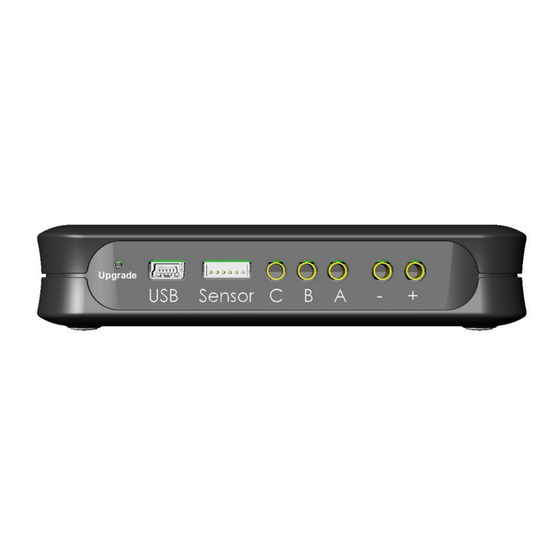
Figure 2: All the connectors to the Motolyser are located
on the side for easy access.
User Guide
Build #114
Advertisement
Table of Contents

Subscribe to Our Youtube Channel
Summary of Contents for MOTOLYSER Build #114
- Page 1 All connections are easily accessed from the side, with the upgrade button located inside the small hole next to the USB port. The Motolyser is powered by 1 or 2-cell Li-Po battery connected to the +/- respectively. In case of wrong polarity the LED on the...
-
Page 2: Quick Start
Quick Start: – Connect the sensor and phase cables to the motor (A, B and C respectively). The connection on the Motolyser side is shown in Figure 2. – Connect the supply battery (1 or 2-cell Li-Po) – Navigate to Motor Current or Condition Test by using the UP/DOWN touch buttons –... -
Page 3: System Information
When the Current Test is started a splash screen is shown asking you to wait for the test to complete. Then you will be automatically redirected to the results, that display information about the test. Step amongst the menu items with the UP/DOWN buttons. 2014-10-05 [Ver 1.2] www.motolyser.com... - Page 4 UP/DOWN buttons. Motor Timing Direction: Indicates the rotating direction of the motor End-Bell: The average timing advanced of the motor end-bell Deviation: Sensor element deviation, how well aligned the sensor elements are aligned. 2014-10-05 [Ver 1.2] www.motolyser.com...
- Page 5 Asymmetry of 0. Firmware upgrade 1. Locate a mini USB cable that will fit the USB port on the Motolyser and your PC 2. Download the Motolyser Feature Upgrade Tool and install as administrator on your PC (Currently Windows only).
-
Page 6: Error Codes
10. While still holding the button, attach USB cable to the USB port on the Motolyser. 11. Display should start flashing, indicating it's ready to receive new firmware. If back-light does not blink, please go back to step 7. 12. You may be prompted to install a driver for the Motolyser at this time.
Need help?
Do you have a question about the Build #114 and is the answer not in the manual?
Questions and answers