
Summary of Contents for DaimlerChrysler TPM-RKE Analyzer 9936
- Page 1 User’s manual TPM-RKE Analyzer 9936 Version 06.03 Daimler Chrysler Reference: QS-258DCA-U...
- Page 2 User guide REGULATORY STATEMENTS This device complies with Part 15 of the FCC Rules. Operation is subject to the following two conditions; (1) this device may not cause harmful interference, and (2) this device must accept any interference received, including interference that may cause undesired operation.
-
Page 3: Table Of Contents
User’s Manual TABLE OF CONTENTS User guide TPM-RKE ANALYZER 9936 ..................... 2 .1 DESCRIPTION OF THE TPM-RKE ANALYZER 9936 ................ 2 .2 FEATURES ............................3 ..1 Radio frequencies ........................... 3 ..2 Type of valve ..........................3 .3 CONNECTORS ............................ 4 ..1 Supply connector .......................... -
Page 4: User Guide
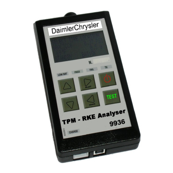
User guide TPM-RKE ANALYZER 9936 DESCRIPTION OF THE TPM-RKE ANALYZER 9936 The principal of this instrument is to awaken and then retrieve data from smart valves mounted on vehicle wheels in order to verify their identifiers. The instrument interacts with the smart valves without contact through wireless communication. -
Page 5: Features
FEATURES ADIO FREQUENCIES Awakening transmission frequency: 125 kHz (LF). Reception frequencies: 433 MHz or 315 MHz (RF). YPE OF VALVE This instrument is especially designed for the measurement of the Siemens and Schrader valves installed into Daimler-Chrysler vehicles. Siemens Siemens Schrader User guide TPM-RKE Analyzer Page 3/20... -
Page 6: Connectors
CONNECTORS UPPLY CONNECTOR To supply the instrument and recharging the internal battery. The voltage of the charger is a 24 V DC. CONNECTOR The USB connector allows the instrument software programs to be updated. StarScan tool can retrieve information through the USB connector. -
Page 7: Description Of The Instrument
DESCRIPTION OF THE INSTRUMENT OWER ON OFF KEY FUNCTION Power on: Press this key to power on the instrument. Power off: Press and hold the key (more than 3 seconds) to power off the instrument. ..1. Power on At power on, it displays the logo. ATEQ VT 60 Then it displays the software revision number. -
Page 8: Front Panel Description
FRONT PANEL DESCRIPTION ISPLAY MAIN MENU The LCD screen displays the parameters menus and > RKE TEST the measurements results. TPM FUNCTIONS SETTINGS IGHTS LOW BAT Battery level light: When this light is on, the battery level is too low, charge it. Pass test light: When this light is on, the instrument has correctly PASS received the frame from the valve (or the RKE). -
Page 9: Battery Supply
BATTERY SUPPLY The instrument uses a Li-ion battery, the autonomy depends of the number of cycles carried out. It battery must be recharged with a 24 V DC external power supply (Included). ATTERY STATUS When the battery is too low, the "LOW BATT" light is flashing for 2 seconds and the instrument will LOW BATT PASS... -
Page 10: Measurement
MEASUREMENT (RKE EY MEASUREMENT TEST MAIN MENU This menu allows putting the instrument in key test > RKE TEST mode (RKE). TPM FUNCTIONS SETTINGS Select this mode with the key, EUROPE RKE TEST the instrument invites you to launch the test by <... -
Page 11: Valve Measurement (Tpm Functions)
(TPM ALVE MEASUREMENT FUNCTIONS Use the following directions to test the functionality of a TPM sensor: MAIN MENU Select "TPM FUNCTION" by using the RKE TEST > TPM FUNCTIONS keys and validate using the key. SETTINGS MODEL YEAR SELECTION > 1997 1998 By using the keys, select the model... - Page 12 LOW BATT PASS FAIL When the "TX" light is flashing, it indicates that the instrument is emitting a frame wirelessly to make the EUROPE valve respond. 2006 .../WK PARK SENSOR TRIGGER PROCESSING First case: a valve is detected: LOW BATT PASS FAIL When the instrument has detected a frame from the...
- Page 13 MAIN MENU > RKE TEST Press the button to return to the main menu. TPM FUNCTIONS SETTINGS ..1. Results explanation The picture below is an example of a valve data communication result: Tire internal pressure at Valve sea level identifier SENSOR DATAS Valve 80AA323B...
-
Page 14: Settings
SETTINGS ARAMETERS MENU This menu will allow the instrument to be configured according to the operator preferences. ..1. Country The parameter "COUNTRY" allows the user to select the geographic valves region. MAIN MENU Select "SETTINGS" by using the RKE TEST TPM FUNCTIONS keys and validate with the key. - Page 15 ..2. Unit The parameter "UNIT" allows the user to choose between the "METRIC" unit and the "US" unit. MAIN MENU Select "SETTINGS" by using the RKE TEST TPM FUNCTIONS keys and validate with the key. > SETTINGS PARAMETERS MENU Select the "UNIT" parameter and validate with the COUNTRY : EUROPE >...
-
Page 16: Auto Off
..3. Auto off The "AUTO OFF" setting allows the user to turn off the instrument automatically after a certain time without use. This is to save the battery before a recharge is required. MAIN MENU Select "SETTINGS" by using the RKE TEST TPM FUNCTIONS keys and validate with the... - Page 17 ..4. Back light The "BACK LIGHT" menu allows the user to adjust the light intensity of the display. The back light increases the battery consumption. MAIN MENU Select "SETTINGS" by using the RKE TEST TPM FUNCTIONS keys and validate with the key.
-
Page 18: Starscan
STARSCAN ATA TRANSFER Data transfer from the TPM/RKE Analyzer 9936 instrument to the StarScan tool. Connect the USB cable from the TPM/RKE Analyzer 9936 instrument to the StarScan tool, then the StarScan tool recognizes the information to download automatically. TPM/RKE A NALYZER PROGRAM UP DATING Connect the USB cable between the computer and the instrument, the USB... -
Page 19: .10 Menu Structure
.10 MENU STRUCTURE AIN MENU MAIN MENU Sub menu 1 Sub menu 2 Sub menu 3 Sub menu 4 RKE TEST > RKE TEST Press <TEST> to start TIRE LOCATION: 1997 > 1998 > > > > Left / right / TPM FUNCTIONS READ SENSOR 1999 >... - Page 20 TIRE LOCATION: DEACTIVATE > Left / right / SENSOR front / rear… SNIFFING MODE TIRE LOCATION: CS > KJ > RS > Left / right / 2005 > READ SENSOR > WK > ZB front / rear… TIRE LOCATION: Left / right / PARK SENSOR >...
-
Page 21: .11 Correspondances Tables
.11 CORRESPONDANCES TABLES EHICLE VALVE Body Valve Vehicle line Model year code manufacturer Prowler 1997-2002 Schrader Viper 2003 - Present Schrader Intrepid/300M 2001 - 2004 Schrader Grand Cherokee 2001 - 2004 Schrader Pacifica 2003.5 - 2004 Schrader Town & Country/Caravan 2002 - 2003 Schrader Town &... -
Page 22: Index
Index Auto off........................ 14 Back light......................15 Battery status......................7 Connectors......................4 Country........................ 12 Description......................2 Display........................6 Key fob........................8 Keys........................6 Lights indicator...................... 6 Measurement......................9 Measurements....................... 8 Menu structure..................... 17 No response......................11 Parameters menu....................12 Parameters setting....................12 Power on.......................
Need help?
Do you have a question about the TPM-RKE Analyzer 9936 and is the answer not in the manual?
Questions and answers