
Subscribe to Our Youtube Channel
Summary of Contents for Kronoterm KT-2
- Page 1 Installation instruction and user manual KT-2 Spatial corrector The manual has to be handed over to the end user after installation. ID.: 17-16-13-2960-03 | 1.2017...
- Page 2 This document is copyrighted. Any use outside the provisions of the copyright law without the permission of Kronoterm d.o.o. is illegal and punishable by law. All previous versions of this document are void. We reserve the right to make changes and printing errors.
-
Page 3: Safety Alerts
Installation The Spatial corrector KT-2 must be installed in a room where the temperature is closest to your desired average temperature of other rooms (hallway, living room). The spatial corrector KT-2 is designed for installation on a flush-mounted electrical socket 3M (GW 24 403 PM). - Page 4 GND connection terminal on the spatial corrector KT-2. NOTE In the case of a direct connection of the spatial corrector KT-2 on the process module(PLC), connect the cables from the spatial corrector KT-2 connected to terminals A+, B-, GND and +12 V to the RJ-45 connector.
-
Page 5: Initial Connection
Initial connection When connecting the data cable to the control panel fort the first time, the regulating circuit setup screen is displayed. SETUP OF CONTROL LOOP Set the desired heating circuit with the keys . Press to confirm the settings. The control panel confirms valid settings with a multi-tone beep. -
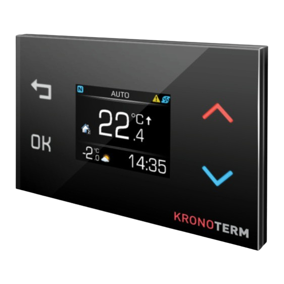
Page 6: Main Screen
► Disconnect the device power supply. ► Reconnect the device power supply. ► Accessing the menu SETUP OF CONTROL LOOP. The menu “Setup of control loop” can be accessed only during the first minute of reconnecting the control panel by holding the keys for 8 seconds. -
Page 7: Child Safety Lock
14 MENU NOTE Contents and display of menus depend on model and configuration of device. Operational setting for Setting night mode: control loop. Fast heating of The display automatically dims in moderate tap water. light. Temperature setting The display automatically dims in low light. for tap water. -
Page 8: System Errors
18 Technical Device Information Dimensions HxWxD: 80x80x8,6 mm The resolution of the temperature sensor 0,1 °C Adjustable range 17 – 27 °C Modbus RS485 connection Max. 4 x KT-2 units can be connected to TT3000 Id.: 17-16-13-2960-03 | 7.2017... - Page 9 Id.: 17-16-13-2960-03 | 7.2017...
- Page 10 Id.: 17-16-13-2960-03 | 7.2017...
- Page 11 Id.: 17-16-13-2960-03 | 7.2017...
- Page 12 The headquarters of the company and place of production Kronoterm d.o.o. Trnava 5e 3303 Gomilsko Tel.: (00386) 3 703 16 20 | Fax: (00386) 3 703 16 33 | Web-page: www.kronoterm.com E-mail: info@kronoterm.com Customer support and service.: (00386) 3 703 16 26 | E-mail: servis@kronoterm.com...
Need help?
Do you have a question about the KT-2 and is the answer not in the manual?
Questions and answers