Table of Contents
Advertisement
Advertisement
Table of Contents

Related Manuals for ENSONIQ ASR-10


Summary of Contents for ENSONIQ ASR-10
- Page 1 ASR-10 Musician’s Manual © 1992 Ensoniq...
- Page 2 ASR-10’s high quality effects on other instruments in your rig, or allow fellow musicians to plug right in and play — no mixer required! The ASR-10 also has the ability to resample sounds with effects in real time. For example: add reverb to a drum sample, resample it, then reuse the effects processor to further color your music.
- Page 3 DI-10 Digital I/O Interface, refer to the DI-10 Manual. Note: If you wish to record the 44.1 kHz digital output of the ASR-10 to a DAT recorder, the DAT recorder must be able to record from its digital input at 44.1 kHz. Some older/consumer DAT recorders do not record at 44.1 kHz as a copy protection scheme: These DAT recorders will not...
- Page 4 Preface Thank-you again for choosing ENSONIQ. Enjoy the music!
- Page 5 Power Insert the line cord into the line receptacle on the back of the ASR-10 (2), next to the power switch (1). Plug the other end of the cable into a grounded AC outlet. The proper voltage for your ASR- 10 is listed on the Serial Number label on the rear panel.
- Page 6 AC Line Conditioning As is the case with any computer device, the ASR-10 is sensitive to sharp peaks and drops in the AC line voltage. Lightning strikes, power drops or sudden and erratic surges in the AC line voltage can scramble the internal memory and, in some cases, damage the unit’s hardware.
- Page 7 For listening through headphones, plug the phones into the rear panel jack marked Phones. If you’re running the ASR-10 through a mixer, in stereo, be sure to pan the left input channel on the mixer fully left, and the right input channel fully right.
- Page 8 Preface Care and Feeding of the Disk Drive The ASR-10’s built-in disk drive is used to store all your Instruments, Banks, and Sequencer data, as well as System Exclusive messages from other MIDI devices. The ASR-10 uses a Quad-density disk drive that can store 1600 Kilobytes of data on a Double-Sided High-Density (DSHD) 3.5”...
- Page 9 We recommend that you use the copied O.S. disk for daily use, and store the original O.S. disk in a safe place. If your O.S. disk becomes damaged and you do not have a back-up copy made, your local Authorized ENSONIQ Dealer can make a new copy for you (you must supply the disk). viii...
- Page 10 • AS –Series Sound Libraries — The AS sound libraries are designed exclusively for the ASR- 10, provided on five High Density disks. • SL, SLT, and ESS Sound Libraries — The ASR-10 can read all of the disks designed for the EPS Series. These disks offer the largest, most accurate, responsive, and musical sampled sounds available anywhere.
- Page 11 Preface ASR-10 Musician’s Manual Need More Help? Whether you’re an aspiring programmer looking for additional information about basic sampling techniques and MIDI theory, or a professional sound designer working with advanced applications, you may want more detailed information that is beyond the scope of this manual.
- Page 12 The following magazines offer many specific articles and columns that can provide a plethora of useful information. THE TRANSONIQ HACKER For prices and more information about this independent news magazine for ENSONIQ Users, call 1-503-227-6848 KEYBOARD For subscription rates and more information call 1-800-289-9919...
-
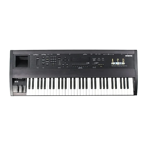
Page 13: Rear Panel Connections
Pedal•CV 1) Power The power switch turns the ASR-10 on and off. When you turn the power on, the display lights up and shows “PLEASE INSERT DISK,” which is the prompt to load the operating system. 2) AC Line In The supplied line cord connects here. - Page 14 Section 1 — Controls and Architecture ASR-10 Musician’s Manual Note: If you are using a single foot switch (SW-2 or SW-6), the Edit/System•MIDI, LEFT FOOT SW parameter should be set to OFF. This will prevent unexpected behaviour. Remember that the Foot Switch jack is optimized for use with a dual foot switch (SW-10), and when a single foot switch is connected, it behaves like the Right Foot Switch.
- Page 15 This jack is for connecting an optional ENSONIQ Model CVP-1 Control Voltage Foot Pedal, which is assignable as a modulator to various parameters within the ASR-10. The pedal gives you a handy alternative modulation source when, for example, you would want to use the Mod Wheel but both hands are busy.
- Page 16 ASR-10’s 44.1 kHz digital output. 10) SCSI Interface This space is for the optional SP-3 SCSI kit that allows the ASR-10 to transfer data to and from a SCSI-compatible hard disk, CD ROM player, or exchange information with computers at very high speed.
- Page 17 Section 1 — Controls and Architecture 14) Audio Input — B/Right and A/Left These jacks are the Right and Left Audio Inputs into the ASR-10 for sampling or Audio Track monitoring of external analog audio sources. SPECS: 140 KOhm input impedance, AC coupled. The Audio Inputs have 2 ranges: Line and Mic.
- Page 18 • LOAD mode is the one you will be in most often — since the ASR-10 lets you continue playing while loading sounds and sequences, LOAD mode also doubles as the “Performance” mode.
- Page 19 The method used to modify or edit programs, presets and system parameters is called Page- driven Parametric Programming, which sounds like a mouthful, but don’t worry. Once you’ve grasped a few basic concepts you’ll find that operating the ASR-10 is quite simple, given its many capabilities.
- Page 20 Instruments Audio Tracks Sequence Tracks 5) Display The ASR-10 Display is divided into two main sections: the Indicator Lights in the top half of the window and the 22-character Alphanumeric Display at the bottom of the window. Sequencer Mode Indicator...
- Page 21 These eight buttons are used to select, deselect, and “stack” the various instruments that are loaded into the internal memory of the ASR-10. For each of the eight locations, the two LEDs above the button indicate whether an instrument is Loaded into that location (red LED lit) and whether it is Selected (yellow LED lit).
- Page 22 Section 1 — Controls and Architecture ASR-10 Musician’s Manual Performance Controllers The ASR-10 features a number of real-time performance controllers that can modify sounds as you play for maximum expressiveness. Three of the most important controllers are located to the left of the keyboard:...
- Page 23 (see Section 9 — WaveSample and Layer Concepts) of the ASR-10. Pressure can be assigned to alter the pitch or volume of voices, filter cutoff frequency, LFO rate or depth, pan location, etc.
- Page 24 “Booting” the ASR-10 Insert the power cord into the line receptacle on the back of the ASR-10, next to the power switch. Plug the other end of the cable into a grounded AC outlet. The proper voltage for your ASR-10 is listed on the Serial Number label on the rear panel.
-
Page 25: About Memory
Here is some important information you should know about purchasing the proper SIMMs: • The ASR-10 was designed to use 1m x 8 or 4m x 8 (Macintosh) non-parity SIMMs (not 1m x 9 or 4m x 9 parity SIMMs). We highly recommend using this type of SIMMs. - Page 26 Edge Connector Internal Memory As it comes out of the box, the ASR-10 contains 2 MegaBytes or 1 MegaWord of internal memory (a word is one single sample, or 16 bits). That’s enough for 31.5 (mono) or 15.75 (stereo) seconds of sampling at a 29.8 KHz sample rate, or about 400,000 notes of sequencer memory.
- Page 27 If you do not have any SIMMs plugged into the Expansion slots, the Memory Expansion Jumper must be installed on the STD (Standard) pins, or the ASR-10 will not boot up (display will be blank).
- Page 28 Section 1 — Controls and Architecture ASR-10 Musician’s Manual About the SIMM Socket The SIMM socket uses the pins on the end of the latching posts to hold the SIMM in place. The alignment notch on the SIMM prevents it from being installed backwards. Once installed, the retaining posts hold the SIMM in place securely, preventing it from dropping out of the socket inside the ASR-10.
- Page 29 Warning The ASR-10 was designed to use 1m x 8 or 4m x 8 non-parity SIMMs (not 1m x 9 or 4m x 9 parity SIMMs). We do not recommend using parity SIMMs. These SIMMs may not operate properly, and may cause damage to the ASR-10.
- Page 30 4. When handling the SIMMs, avoid touching the connector pins. Try to handle the SIMMs by the edges only. If you have any questions concerning the use of SIMMs, the ASR-10, or for additional technical support, please contact ENSONIQ Customer Service at (610) 647-3930 Monday through Friday 9:30 a.m.
- Page 31 INST STOP When the LOAD indicator is flashing, the ASR-10 is showing you disk files (think of it as a question mark — the ASR-10 is saying “Load the file showing on the display?”). Pressing the Up/Down Arrow buttons takes you through the files on the disk. If there are none, the display will read “NO INST OR BANK FILES.”...
- Page 32 If you tell the ASR-10 to load an instrument into a location that already has an instrument loaded (left red LED lit), the new instrument will be loaded into that location and the one that was there will be automatically deleted.
- Page 33 About Banks Banks provide a way to load a whole group of instruments and sequences into the ASR-10 with a few button presses. When you save a bank to disk, it is like taking a “snapshot” of the contents of the ASR-10 Internal memory —...
- Page 34 • Press Enter•Yes. The ASR-10 will resume loading until completed, or until the point when it needs another disk. • When it has finished loading the instruments, the ASR-10 will load the song (if any) and then set up any copied instruments included in the bank.
- Page 35 The range of an instrument can be as much as the full 127 keys of the MIDI Specification (for playing the ASR-10 from an external controller via MIDI) or as little as a single key. Up to eight instruments can inhabit the keyboard in a way that might be termed a “Pile o’ Instruments.”...
- Page 36 So it is with instruments loaded into the ASR-10 in Load mode. When you select an instrument, it is brought to the top of the pile. That is, you will hear the most recently selected instrument over its whole range when you play the keyboard.
- Page 37 Section 1 — Controls and Architecture If you select the piano, it will play over the whole keyboard, covering up the bass entirely: Piano Bass Now you select the bass. This brings it to the top of the pile, and it covers up the piano, but only in the region where their ranges overlap (the bottom two octaves): Bass Piano...
- Page 38 ASR-10 Musician’s Manual Loading Sequencer Data There are two ways that ASR-10 Sequencer data can be stored on a disk: • SONG File. A song file contains a song and all its related sequences. Loading a song file from disk will completely erase the current contents of the ASR-10 sequencer memory, replacing whatever is there with the song and sequences from the disk file.
- Page 39 Section 1 — Controls and Architecture Selecting a Sequence/Song Press the Edit button, then the Seq•Song button. The following screen will appear: STOP EDIT Current Sequence Bar and Beat Location within or Song current Sequence or Song This screen is where you select a sequence or the song. With the selected sequence or song underlined (as shown above), use the Up/Down Arrow buttons or the Data Entry Slider to select a different sequence or song.
- Page 40 SPACE. Save the sequence to another disk (or delete some files from the disk). • If you try to SAVE CURRENT SEQUENCE while the song is selected, the ASR-10 will not execute the command, responding USE SAVE SONG + ALL. Again, make sure the sequence is selected before trying to save it.
- Page 41 Once you have created a song or made changes to an existing one, you can save the song to a formatted ASR-10 disk. In addition to saving the song itself, the SAVE SONG + ALL SEQS command saves all the individual sequences currently in memory (whether they are part of the song or not).
- Page 42 The ASR-10’s 16-bit stereo output converters provide 96dB of dynamic range. This figure of 96dB is referred to as the system headroom. Since the ASR-10 is capable of playing 31 notes of polyphony, this 96dB of system headroom must be divided amongst these 31 voices. If the output level of all sustaining voices exceeds 96dB, this will result in clipping.
- Page 43 Section 1 — Controls and Architecture Normal Sample Normal Sample Attenuated Sample Playback Attenuation Combined Samples -12dB still remain within the system headroom -12dB Drum Sample Drum Sample Playback without Attenuation The BOOST parameter should not be turned on for all WaveSamples. Sustaining sounds can remain at their peak volume for as long as a key is held down.
- Page 44 ASR-10 Musician’s Manual Parameter Illustrations The ASR-10 accesses parameters and commands through Pages. Each page is accessed by two button presses, the first being a Mode button and the second a Page button. Most parameters will also have a Direct-Dial number. This number can be pressed immediately after pressing the proper Mode and Page button to get to a specific parameter directly, bypassing scrolling with the Left/Right Arrow buttons.
- Page 45 Use this parameter to adjust the pitch bend range. The bend range is adjustable in one-semitone increments from 0 to 12. Each ASR-10 WaveSample can have its own bend range (which will override the global bend range) or can use this global bend range.
- Page 46 Track(s), and it will be transmitted via MIDI as MIDI controller #7. When PEDAL=MOD, it will affect any modulation destination that has PEDAL selected as a modulator, and it will be transmitted via MIDI as MIDI controller #4. When PEDAL= VOLUME the ASR-10 will still receive PEDAL (MIDI controller #4) messages via MIDI.
- Page 47 Switch is permanently dedicated to function as the Sustain pedal. • OFF — This setting makes the ASR-10 ignore the Left Foot Switch. If you are using the single foot switch (SW-2) which came with the ASR-10, then you should keep this parameter set to OFF (the SW-2 will only function as a sustain pedal).
-
Page 48: Midi Parameters
Selects the Base Channel on which the ASR-10 transmits and receives MIDI messages. The base channel is used to receive MIDI data while the ASR-10 is in POLY and MONO A modes. This is the MIDI channel that the ASR-10 will transmit on when Edit/System•MIDI, TRANSMIT ON=BASE CHANNEL. - Page 49 There are five MIDI modes implemented in the ASR-10: • OMNI — In this mode the ASR-10 will receive on all 16 MIDI channels. This mode is useful when you are only using a few instruments, and you are not concerned with setting up different channels for each device.
- Page 50 For example, each guitar string on a MIDI guitar can send independent pitch bend, while the “whammy bar” controller could be sent on the global channel to affect all voices. The ASR-10 will not receive note data via MIDI on the base channel minus one in MONO A and Note: B modes.
- Page 51 ASR-10 will neither transmit nor receive System Exclusive messages. Note: This parameter does not have to be ON for the ASR-10 to record and store Sys-Ex messages from external devices using the MIDI SYS-EX RECORDER function on the Command/System•MIDI page.
- Page 52 Instrument•Sequence Track’s Edit/Track MULTI-IN MIDI CHANNEL. To load a Bank file, send the ASR-10 a program change that is the Bank file number +1. When a program change is received, the ASR-10 will load the appropriate file from the currently selected storage device (FLOPPY, SCSI 0-7).
- Page 53 Setting this to ON is useful if you are playing the ASR-10 from an external drum pad or guitar controller in MULTI or MONO B modes and want local controllers to affect all the tracks.
- Page 54 Use the Data Entry Slider and the Arrow buttons to give the disk a unique name by which you can identify that disk. This is very important, as the ASR-10 will ask you for this disk by name if an instrument or song on the disk is used in a bank. Also, make sure you write the Disk Label name on the outside of each disk after you are done formatting it.
- Page 55 SYSTEM•MIDI Press Command / System•MIDI / 1 Use this command to put the ASR-10 Operating System (O.S.) on a new disk that you have formatted, or to update the Operating System on an existing disk with a newer version. The Operating System can only be copied to a blank disk, or a disk (with or without sounds and Note: sequences) that has an existing operating system on it.
- Page 56 Operating System in the disk drive. • Press Enter•Yes. The display reads DISK COMMAND COMPLETED. The next time you “boot” the ASR-10 with that disk, the new settings will be loaded in as the defaults.
- Page 57 (both High Density disks or both Double Density disks). It is a good practice to regularly back up your valuable data — including the O.S. disk that came with the ASR-10 — in this way. You can use either blank or formatted disks. During the COPY FLOPPY DISK command, the ASR-10 will ask you if you want to format the blank disk.
- Page 58 The ASR-10 can be used to receive, store, and send MIDI System Exclusive (Sys-Ex) messages. These Sys-Ex messages can be saved to and loaded from disk. Since the ASR-10 erases the Internal Memory to “buffer” incoming Sys-Ex signals, you should make sure that any important data has been saved to disk before performing this command.
- Page 59 Press Command / System•MIDI / scroll using the arrow buttons This command is used to label ASR-10 disks with a unique seven character Disk I.D. These labels are used to give each of your ASR-10 disks a unique identity, thereby allowing banks to load from multiple disks.
- Page 60 TO DRIVE and FROM DRIVE parameters to the same number. Press Enter•Yes. • If the destination drive needs to be formatted, the ASR-10 will display the message FORMAT SCSI DRIVE. Pressing Enter•Yes will cause the drive to be formatted. Immediately afterward, the ASR-10 begins copying the data from the source drive to the destination drive.
- Page 61 This allows you to select the device that you want to use to store the backup data. You may select SCSI 0 through 7, or the FLOPPY drive. Press Enter•Yes, and the ASR-10 will proceed with either BACKUP or RESTORE.
- Page 62 Insert a disk and press Enter•Yes. If you insert an unformatted disk (or cartridge), the ASR-10 will automatically format it. If the disk is not blank, the ASR-10 will erase the files on the disk before proceeding to copy files to it. As you insert each disk, be sure to write the disk number somewhere on the disk label.
- Page 63 The ASR-10 will restore the files one at a time. You will be prompted to insert each disk when necessary. If you insert the wrong-numbered disk, the ASR-10 will show WRONG DISK INSERTED.
- Page 64 Section 2 — System•MIDI ASR-10 Musician’s Manual CONFIGURE AUDIO TRACKS SYSTEM•MIDI Press Command / System•MIDI / scroll using the arrow buttons SYSTEM STOP This command enables and disables Audio Track playback and recording. It also determines whether Audio Tracks will be recorded direct-to-disk via the SCSI port, or whether they will reside in RAM and must be manually saved to disk as part of a SONG + ALL SEQS file.
- Page 65 Macros allow you to do this. In the ASR-10, a macro is a shortcut command that allows you to get to a file or directory on your SCSI Storage Device (or floppy) with just two or three button presses.
- Page 66 • Press and hold the Load button, type and release the number of the desired macro. When you release the Load button, the ASR-10 will go to the file that is assigned to the macro. If the file is a directory, you will need to press Enter•Yes to actually enter the directory. If no file is assigned to the macro, the macro number will be displayed, and nothing else will happen.
- Page 67 • While continuing to hold the Load button, enter the four-digit Direct Macro number on the ASR-10 keypad. • Release the Load button. As soon as the ASR-10 has located the Instrument on the CD-ROM disk it will display the Instrument name.
- Page 68 Instruments The ASR-10 keeps all its sounds in a format called an Instrument. This format is used for all disk storage. The internal structure of an Instrument has three levels: Instrument, Layer, and WaveSample.
- Page 69 INST STOP When the LOAD indicator is flashing, the ASR-10 is showing you disk files (think of it as a question mark — the ASR-10 is saying “Load the file showing on the display?”). Pressing the Up/Down Arrow buttons takes you through the files on the disk. If there are none, the display will read “NO INST OR BANK FILES.”...
- Page 70 Banks Banks provide a way to load a whole group of instruments and sequences into the ASR-10 with a few button presses. When you save a Bank to disk, it is like taking a “snapshot” of the contents of the ASR-10 internal memory. The Bank file stores the following information: •...
- Page 71 Instrument or Song, the ASR-10 “remembers” what disk it was loaded from. When you load a Bank file, the ASR-10 will ask by name for any disks it needs to load the files included in the Bank. This is why it is very important that you give each of your disks a unique name (Disk Label ID) and write that name on the disk itself.
- Page 72 Saving the Contents of Memory as a Bank Saving a bank is like taking a “snapshot” of the contents of the ASR-10 memory. When you later load a bank, the ASR-10 “looks” at that snapshot and tries to recreate what was in memory when the bank was saved.
- Page 73 ASR-10 Musician’s Manual Performance Presets Once you have a number of instruments loaded into the ASR-10, there are so many possible combinations for selecting, stacking, mixing, and manipulating the ranges of those instruments that it can get a bit hard to manage during a performance. That is where Performance Presets come in.
- Page 74 Section 3 — Instrument, Bank, and Preset Concepts Note: When the LOAD indicator is flashing, the display is showing you disk files for loading. When the LOAD indicator is lit but not flashing, the display is showing you the name(s) of the of instruments in the Internal Memory.
- Page 75 “accompaniment” sound and your right hand plays a “solo” sound. This is easy to set up on the ASR-10 by stacking the two sounds and assigning them different INST (key) RANGES. You can save this arrangement as a preset so that any time you select that preset, you’ll recall the keyboard split.
- Page 76 Section 4 — Instrument, Bank, & Preset Parameters This section offers detailed descriptions of the commands and parameters used in selecting, creating, and editing Instruments, Banks and Performance Presets. For an overview of the concepts involved, refer to the previous section. Edit/Instrument Page The parameters on this page are used to modify the individual Instrument(s).
- Page 77 Section 4 — Instrument, Bank, and Preset Parameters ASR-10 Musician’s Manual Here’s how a typical instrument might react when you press the different patch select buttons: With neither Patch The Display Select button pressed: shows: The Display Patch shows: Select...
- Page 78 TRANSMIT ON= parameter on the EDIT/System•MIDI page is set to INST CHANNEL. Any of the 16 MIDI channels can be selected. If TRANSMIT ON=BASE CHANNEL, the ASR-10 will only transmit on the Base MIDI channel (also on the EDIT/System•MIDI page) no matter which MIDI channel is selected.
- Page 79 When PRESSURE MODE=KEY: • Local voices played from the ASR-10 keyboard will respond to key pressure only. • The sequencer will record key pressure into any tracks you record. • The sequencer will play back any key pressure messages recorded on the track, and will ignore any channel pressure on the track.
- Page 80 MIDI device from the ASR-10 and pressure doesn’t seem to have an effect, it could be the ASR-10 is set to transmit key pressure and the receiving instrument only recognizes channel pressure. In this case, set this parameter to PRESSURE MODE= CHAN when playing or sequencing that instrument.
- Page 81 Section 4 — Instrument, Bank, and Preset Parameters ASR-10 Musician’s Manual SIZE (in blocks) EDIT INST Press Edit / Instrument / 7 This display shows how much internal memory the instrument occupies. This is a readout only and can’t be modified. Size is shown in Blocks. One Block=256 samples (or words). Four Blocks=1k sample/word.
- Page 82 Press Edit / Instrument / scroll using the arrow buttons This parameter allows you to set the keyboard range of the instrument. Keyboard ranges are very important in the creation of keyboard splits and layers. The ASR-10 allows you to set the keyboard range in a very easy fashion.
- Page 83 Section 4 — Instrument, Bank, and Preset Parameters ASR-10 Musician’s Manual Command/Instrument Page CREATE NEW INSTRUMENT INST Press Command / Instrument / 0 Use this command to create a new instrument. This is useful for creating instruments that will only play out via MIDI (MIDI Instruments).
- Page 84 Use this command to save the current Bank. Banks provide a way to load a whole group of instruments and sequences into the ASR-10 with a few button presses. When you save a Bank to disk, it is like taking a “snapshot” of the contents of the ASR-10 internal memory. The Bank file stores the following information: •...
- Page 85 Section 4 — Instrument, Bank, and Preset Parameters ASR-10 Musician’s Manual SEQS command on the Command/Seq•Song page. • Select SAVE BANK. • Press Enter•Yes. The display shows: INST STOP The display shows the current name with a cursor (underline) beneath the first character. If you want to give the bank a new name, do so at this time.
- Page 86 Section 4 — Instrument, Bank, and Preset Parameters • Press Load to return to the “Pile.” Pressing the number that you selected for the preset will now instantly recall this keyboard configuration. Repeat this procedure for each performance preset you want to create, selecting a new number (from 1-8) for each. This function is labeled on the front panel as (Create Preset) under the Command button.
- Page 87 Understanding ASR-10 Effects The ASR-10 has a powerful built in signal processor that can produce an extraordinary variety of effects. What is more important, its functions are integrated with, rather than added onto, the rest of the sampler. The flexible bus routing scheme and the extensive real-time control give the ASR-10 its dynamic effects capability.
- Page 88 However, they differ in the fact that while the Bank Effect can be replaced, the ROM Effects are stored in Read Only Memory and will always reside in the ASR-10. Even after turning off the ASR-10, the ROM Effects will stay in memory.
- Page 89 (see the preceding discussion on effect types). Selecting a new effect will automatically set all of the effect parameters to their default values for the new effect. The ROM Effects, those that always reside within the internal memory of the ASR-10, are selected here. ROM Effects List...
- Page 90 Section 5 — Effect Concepts ASR-10 Musician’s Manual SMALL ROOM An ambient room reverb LARGE ROOM A room reverb with larger ambience HALL REVERB2 This hall reverb offers a large acoustic space SMALL PLATE A tight sounding plate reverb LARGE PLATE...
- Page 91 The complete effects setup, including the values of all effect parameters, is saved when you save an instrument. It is also saved with each bank. The ASR-10 is smart about switching effects, since all sound must stop for an instant when it changes effects.
- Page 92 Loading and Saving ASR-10 Effects Loading an Effect File You can load an effect from disk into the internal memory of the ASR-10. The effect will load into the Bank effect location, replacing whatever effect was there previously. First, insert a disk containing one or more effect files into the disk drive.
-
Page 93: Programming Effects
The Effects Busses The output of every voice in the ASR-10 is assigned to a stereo bus. A bus, like the bus of a mixing board, mixes together all the voices assigned to that bus into a single stereo pair. Of the... -
Page 94: Single Function Effect Mixer
Section 5 — Effect Concepts ASR-10 Musician’s Manual Single Function Effect Mixer Destination Bus BUS1 Voice Output BUS1 Main Effect 1 Outputs BUS2 BUS2 BUS3 BUS3 Output Expander AUX 1 AUX 2 Output Expander AUX 3 Output Expander The above diagram shows the effects busses and the output mixing. Every voice is assigned to one of the four stereo busses, which go around or through the effects processing. - Page 95 Section 5 — Effect Concepts Triple Function Effect Mixer Destination Bus BUS1 Voice Output Effect 1 BUS1 Main Effect 2 Outputs BUS2 BUS2 Effect 3 BUS3 BUS3 Output Expander AUX 1 AUX 2 Output Expander AUX 3 Output Expander Some effects, such as DIST+CHO+REV, use the above mixing scheme. Effect 1 and Effect 2 usually have a Dry/Wet mix within them.
- Page 96 Section 5 — Effect Concepts ASR-10 Musician’s Manual Predefined Effect Modulation Parameters Several of the effects allow real-time control of a single predefined parameter within the effect, such as the Reverb Mix or Flanger Feedback. Each of these effects will have its own Modulator Select screen, where the modulator and mod amount are selected.
- Page 97 Section 5 — Effect Concepts Selectable Effect Modulation Parameters Most of the effects allow real-time control of selectable parameters and share common modulation control parameters. Within these effects, each Effect Variation can have two different Modulation Sources, Destination parameters, and defined modulation ranges (for a total of eight different modulatable parameters).
- Page 98 Section 6 — Effect Parameters This section offers detailed descriptions of the commands and parameters used in selecting, creating, and editing effects. For a basic overview of the concepts involved, refer to the previous section. Command/Effects Page The commands on this page allow you to copy and save effects. SAVE BANK EFFECT EFFECTS Press Command / Effects / 0...
- Page 99 Section 6 — Effect Parameters ASR-10 Musician’s Manual Edit/Effects Page Each of the effects has multiple screens containing a particular set of parameters associated with that effect. Press the Edit button, followed by the Effects button to access these parameters.
- Page 100 Section 6 — Effect Parameters DETUNE AMT Range: 0 to 99 This parameter controls the depth of the detuning, that is, how much the pitch will change. Low values yield a metallic sound. Some voices sound best with very low values. PRE-DELAY TIME ROOM and HALL REVERB Range: 0 to 500 44KHZ REVERB Range: 0 to 340...
- Page 101 Section 6 — Effect Parameters ASR-10 Musician’s Manual EARLY RFLECTION LEV Range: 0 to 99 Controls the level of pre-echoes of the input signal added directly to the reverb output. Range: 0 to 99 CHORUS RATE This parameter controls the four rates of modulation of the delay time of the chorus. The delay modulation produces vibrato and tremolo.
- Page 102 Section 6 — Effect Parameters PHASE DEPTH Range: 0 to 99 This parameter controls the depth of the notches created by the phasing. ROM-08 FLANGER+REV The FLANGER+REV algorithm is similar to the Chorus+Reverb algorithm with a single LFO. Assign a voice to BUS1 to get the flanger plus reverb, and use BUS2 for reverb only. BUS3 is dry. Range: 0 to 99 BUS1 REVERB MIX...
- Page 103 Section 6 — Effect Parameters ASR-10 Musician’s Manual REVERB DECAY TIME DIFFUSION HI FREQ DAMPING See the descriptions under Hall Reverb. Range: 0 to 99 ROTOR FAST Determines the rate of the rotary speaker when in the “Fast” setting. The higher the value, the faster the rate.
- Page 104 Section 6 — Effect Parameters BUS1 REV AFTER CHOR REVERB DETUNE RATE/AMT BUS2 REVERB MIX CHORUS RATE/AMT REVERB DECAY TIME CHORUS MIX LOW FREQ DECAY CHORUS FEEDBACK HI FREQ DAMPING See the descriptions under Chorus+Reverb. BUS3 DDL MIX Range: 0 to 99 The BUS3 DDL Mix determines the Dry/Wet mix of the Digital Delay.
- Page 105 Section 6 — Effect Parameters ASR-10 Musician’s Manual DIST GAIN IN and OUT Ranges: 0 to 99 These two parameters control the levels going into and coming out of the distortion effect. For more distortion, use a high input level and turn the output level down to keep the volume under control.
- Page 106 Section 6 — Effect Parameters DISTORTION MIX Range: 0 to 99 Determines the Dry/Wet, or in this case, dirty/clean mix of the signal. A value of 0 yields a clean signal; 99 yields an all distortion signal. REVERB DECAY TIME HI FREQ BANDWIDTH LOW FREQ DECAY REVERB DETUNE RATE/AMT...
- Page 107 Section 6 — Effect Parameters ROM-14 SMALL ROOM ROM-15 LARGE ROOM ROM-16 HALL REVERB2 These three algorithms offer a studio quality reverb that can be controlled with a high degree of precision. The BUS1 and BUS2 parameters can be routed into the effect with different Dry/Wet mixes.
- Page 108 Section 6 — Effect Parameters ASR-10 Musician’s Manual PREDELAY TIME Range: 0 to 450 ms Controls the amount of time it takes for the original signal to be presented to the reverb. Higher values denote a longer delay. Range: -99 to +99...
- Page 109 Section 6 — Effect Parameters REFL 1 LEVEL Range: 0 to 99 This parameter controls the level of the first pre-echo. This pre-level controls the echo send to the Definition. Range: 0 to 99 REFL 1 SEND This parameter controls the level of the first pre-echo, with the echo routed directly to the output. REFL 2 TIME Range: 0 to 120 milliseconds...
- Page 110 Section 6 — Effect Parameters ASR-10 Musician’s Manual values of the components (not user programmable) differentiate the large and small plate reverbs. The signal goes directly through the diffusers which smear the signal. The signal is then routed to a larger diffuser, known as Decay Definition, and is diffused over a period of time (creating a decay).
- Page 111 Section 6 — Effect Parameters L/R BALANCE Range: -99 to +99 This parameter controls the left/right stereo balance of the plate reverb signal. A setting of -99 would offer hard left, whereas a setting of +99 would offer hard right. A setting of +0 would place the reverb in the center of the stereo spectrum.
- Page 112 Section 6 — Effect Parameters ASR-10 Musician’s Manual HF DAMPING Range: 0 to 99 This parameter sounds best when set to low values. It has the same function as in the Plate Reverb, which is to filter out more and more high frequency energy. For the most natural sounding reverse effect, we recommend a setting of 0.
- Page 113 It is however, the output amplitude over which the user has control. The ASR-10 offers a highly controllable gated reverb, optimized for percussive instruments, but useful for any input signal. The gate is first opened when the input signal passes the trigger threshold.
- Page 114 Section 6 — Effect Parameters ASR-10 Musician’s Manual BUS1 and BUS2 parameters can be routed into the effect with different Dry/Wet mixes. Gated Reverb with a High Retrigger Threshold Hold Time Release Attack Time Retrigger Level Trigger Signal Time Gated Reverb with a Low Retrigger Threshold...
- Page 115 Section 6 — Effect Parameters TRIGGER THRESH Range: -96 to +0 dB This parameter sets the signal level that triggers the gated reverb. When the incoming signal reaches this value, it triggers (starts) the gated reverb. Higher values would require a stronger incoming signal.
- Page 116 Section 6 — Effect Parameters ASR-10 Musician’s Manual ROM-22 NLIN REVRB 1 ROM-23 NLIN REVRB 2 ROM-24 NLIN REVRB 3 Non Lin Reverbs can be used to obtain blooming reverb, gated reverb, reverse reverb and early reflections. In general, they do not produce an exponentially decaying reverb. Unlike the Hall, Room and Plate reverbs, NLIN REVRB 1, 2, and 3 pass the input signal through the reverb diffusers only once.
- Page 117 Section 6 — Effect Parameters frequency energy to be filtered out. Range: 1 to 99 HF BANDWIDTH The high frequency bandwidth parameter acts as a low pass filter on the output signal, controlling the amount of high frequencies that will be heard. The higher the setting the more high frequencies are heard.
- Page 118 Section 6 — Effect Parameters ASR-10 Musician’s Manual ROM-25 MULTITAP DDL MULTITAP DDL produces four independent controllable delays. The BUS1, BUS2, and BUS3 MIX parameters can be routed into the effect with different dry/wet mixes. This algorithm sounds best with a mix of wet and dry.
- Page 119 Section 6 — Effect Parameters ROM-26 EQ + DELAY LFO EQ + DELAY LFO features a stereo digital delay that provides LFO modulation of a wide range of delays. This algorithm sounds great with an electric piano, but try it with any source! EQ+DELAY LFO Signal Routing Regen Damping...
- Page 120 Section 6 — Effect Parameters ASR-10 Musician’s Manual DLY CROSS REGEN Range: -99 to +99 This parameter allows you to feedback the delayed signals to their opposite sides; the left voice crosses to the right voice, and the right voice crosses to the left voice. A setting of +99 or -99 will cause infinite delay.
- Page 121 Section 6 — Effect Parameters ROM-27 VCF+DISTORT VCF+DISTORT combines a voltage control filter and a raspy distortion. Three effects can be obtained: Distortion, Wah-wah, and Auto-wah. The last two functions use the same VCF. These filters can be disabled or used as EQ if desired. There is a second VCF that exists after the distortion.
- Page 122 Section 6 — Effect Parameters ASR-10 Musician’s Manual POST-DIST VCF FC Range: 01 to 99 This parameter determines the filter cut off frequency after the distortion. Higher values have a brighter sound. This parameter can also be modulated, using a CV Pedal for a wah-wah pedal effect.
- Page 123 Section 6 — Effect Parameters The parameters available for this algorithm are: Range: -48 to +48 dB PREAMP GAIN This parameter adjusts the amount of boost or cut applied to the incoming signal. We recommend a setting of +0 dB, since these emulations were optimized for distortion there. Lower preamp gains will result in less distortion, while higher preamp gains will yield clipping distortion.
- Page 124 Section 6 — Effect Parameters ASR-10 Musician’s Manual EQ1 FC Range: 0 to 9999 Hz This parameter determines the filter center frequency of the parametric in the main amp stage. Higher values have a brighter sound. Range: -48 to +24 dB GAIN This parameter adjusts the amount of boost or cut applied to the main amp parametric.
- Page 125 Section 6 — Effect Parameters PRE-EQ FC Range: 0 to 9999 Hz This parameter determines the filter center frequency of the parametric in the preamp stage. Higher values have a brighter sound. Range: -48 to +24 dB PRE-EQ GAIN This parameter adjusts the amount of boost or cut applied to the preamp parametric. PRE-EQ Q Range: 1 to 18...
- Page 126 Section 6 — Effect Parameters ASR-10 Musician’s Manual GAIN Range: -48 to +24 dB This parameter adjusts the amount of boost or cut applied to the second main amp parametric. Range: 1 to 18 EQ2 Q This parameter determines the width of the resonant peak of the second filter center.
- Page 127 Section 6 — Effect Parameters MID2 FC MID3 FC GAIN GAIN MID2 Q MID3 Q These parameters are identical to the previous ones, but can be assigned to control different bandwidths within the mid-range. Range: -24 to +0 dB INPUT TRIM This parameter allows you to adjust the input level before the EQs to eliminate the possibility of clipping boosted signals.
- Page 128 Section 6 — Effect Parameters ASR-10 Musician’s Manual The parameters available for the EQ+CHOR+DDL are: Range: 0 to 99 CHOR RATE This parameter controls the rate of pitch modulation which is the chorus. To achieve chorusing, this rate must be very slow.
- Page 129 Section 6 — Effect Parameters GAIN Range: -48 to +24 dB This parameter sets the amount of boost or cut applied to the high shelving filter. Range: -24 to +00 dB EQ TRIM This parameter allows you to adjust the input volume of the EQs to eliminate the possibility of clipping boosted signals.
- Page 130 Section 6 — Effect Parameters ASR-10 Musician’s Manual L/R LFO Range: OUT-OF-PHASE or IN-PHASE This parameter controls the vibrato pitch direction of the left and right channels. When OUT-OF- PHASE, the quadrature pitch change on the left channel will lag 90˚ from the right. When IN- PHASE, both channels will change pitch together.
- Page 131 Section 6 — Effect Parameters ROM-35 EQ+FLNGR+DDL EQ+FLNGR+DDL combines an EQ with a flanger and a digital delay. Use flanging to get that “jet aircraft woosh” effect. EQ+FLANGER+DDL Signal Routing BUS1 Left Flanger Delay Echo BUS2 Left Echo Main Level Input Level Trim Delay Outputs...
- Page 132 Section 6 — Effect Parameters ASR-10 Musician’s Manual This parameter controls the time delay for the right channel regen delay. This is the “pong.” Range: -99 to +99 DELAY FEEDBACK This parameter controls the level of the delay time taps. The sign of the value determines the polarity of the feedback.
- Page 133 Section 6 — Effect Parameters ROM-36 EQ+TREM+DDL EQ+TREM+DDL combines a tremolo effect, which is a pulsating change in volume, with an EQ and a digital delay. EQ+TREM+DDL Signal Routing BUS2 Delay BUS1 Left Tremolo Echo Echo Main Level Input Level Trim Regen Outputs Tremolo...
- Page 134 Section 6 — Effect Parameters ASR-10 Musician’s Manual DLY TIME L Range: 0 to 1500 ms This parameter controls the time delay for the left channel regen delay, and has nothing to do with the tremolo effect. Range: 0 to 1500 ms DLY TIME R This parameter controls the time delay for the right channel regen delay.
- Page 135 Section 6 — Effect Parameters to the right channel. This delay topology achieves a 1.5 second ping-pong effect, and is very effective as a “poor man’s reverb.” The BUS1 and BUS2 parameters can be routed into the effect with different Dry/Wet mixes. BUS3 (not shown) is a dry path. Phaser+DDL Signal Routing Delay Feedback BUS1 Left...
- Page 136 Section 6 — Effect Parameters ASR-10 Musician’s Manual SAMPLE/HOLD RATE Range: 0 to 100 This parameter controls the sample rate of a sample and hold network applied to the LFO within the phaser. When in hold, the effect will be to create momentarily fixed notches within the frequency spectrum (if the notch depth is not +0).
- Page 137 ROM-39 PITCH SHIFT The Pitch Shifters allow you to change the pitch of a signal to any pitch desired within a range of one octave in either direction. The ASR-10 offers three different pitch shift algorithms, each designed with a different purpose: •...
- Page 138 Section 6 — Effect Parameters ASR-10 Musician’s Manual popular because for low pitch shift ratios, splicing is infrequent. These pitch shifters can create very interesting stereo fields by panning each of two pitch shifted voices selectively, and because of the inherent time delay modulation of the algorithm. The BUS1 and BUS2 parameters can be routed into the effect with different Dry/Wet mixes.
- Page 139 Section 6 — Effect Parameters MOD SRC 1 MOD SRC 2 DST 1 DST 2 MIN 1 MIN 2 MAX 1 MAX 2 These parameters are explained in detail in Section 5 — Effect Concepts. When KBD is selected as a MOD SRC, and VC1 SEMI or VC2 SEMI is selected as the DST Note: (destination), the pitch will increase one semitone at a time above middle C (C4), and decrease one semitone at a time below middle C (Middle C being zero).
- Page 140 Section 6 — Effect Parameters ASR-10 Musician’s Manual VC 2 SEMI Range: -12 to +12 This parameter allows you to adjust the pitch of Voice 2 up to an octave above or below the original pitch in semi-tones. Range: -99 to +99 VC 2 FINE This parameter allows you to fine tune the pitch of Voice 2.
- Page 141 Section 6 — Effect Parameters The parameters available for this algorithm are: Range: -99 to +99 VOICE 1 FINE This parameter allows you to fine tune the pitch of Voice 1. VOICE 1 VOL Range: 0 to 99 This parameter allows you to adjust the volume of Voice 1. A setting of 0 would eliminate any audible pitch shift.
- Page 142 Section 6 — Effect Parameters ASR-10 Musician’s Manual The parameters available for this algorithm are: Range: -48 to +48 dB COMP GAIN This parameter boosts the compressed signal level. COMP RATIO Range: 1/1 to 40/1, infinity This parameter sets the amount of compression. The range is based on decibels (dB) above the threshold.
- Page 143 Section 6 — Effect Parameters These parameters are explained in detail in Section 5 — Effect Concepts. Edit/Effect Parameters...
- Page 144 Section 6 — Effect Parameters ASR-10 Musician’s Manual ROM-43 EXPANDER EXPANDER performs downward expansion of input signals. For high expansion ratios this algorithm functions as a gate. This algorithm operates by expanding (attenuating) signals below the threshold and passing the signals above the threshold. The Threshold is a parameter defined by the user.
- Page 145 Section 6 — Effect Parameters TRIGGER MASK Range: OFF or ON This parameter enables the trigger mask function. Once triggered, the side chain detector will see no input signal for a duration specified by the TRIGGER TIME. Range: 1ms to 10.0s TRIGGER TIME This parameter sets the duration over which the side chain detector will be blacked out.
- Page 146 Section 6 — Effect Parameters ASR-10 Musician’s Manual THRESHOLD Range: -96 to +0 dB This parameter sets the threshold level. Signals that exceed this level will be unaffected, while signals that are below will be expanded. To turn off the expander, set the level to -96 dB.
- Page 147 Section 6 — Effect Parameters ROM-45 INVRS EXPNDR INVRS EXPNDR creates sustain by expanding the signal so that the signal levels above threshold are passed and levels below threshold are boosted to create a more even sound. A traditional expander would have the opposite effect: that is a signal level below threshold would be attenuated.
- Page 148 Section 6 — Effect Parameters ASR-10 Musician’s Manual GAIN Range: -48 to +24 dB This parameter sets the amount of boost or cut applied to the high shelving filter. Range: -24 to +0 dB EQ TRIM This parameter allows you to adjust the level of the signal entering the EQ, to eliminate the possibility of clipping boosted signals.
- Page 149 Section 6 — Effect Parameters RELEASE TIME Range: 1ms to 10.0s This parameter determines how long it takes for the compression to be fully deactivated after the input signal drops below the threshold level. This is generally chosen longer than the attack time.
- Page 150 Section 6 — Effect Parameters ASR-10 Musician’s Manual ROM-47 DUCKER The DUCKER algorithm is a compressor that automatically lowers the level of a signal (such as music) when another signal (like an announcer voice-over) comes in. When the voice-over leaves, the level of the original signal is restored. This algorithm is useful for voice-overs, Rap, and DJ work.
- Page 151 Section 6 — Effect Parameters RELEASE TIME Range: 1ms to 10.0s This parameter determines how long it takes for the compression to be fully deactivated after the input signal drops below the threshold level. This is generally chosen longer than the ATTACK TIME.
- Page 152 Section 6 — Effect Parameters ASR-10 Musician’s Manual ROM-48 RUMBLE FILTR RUMBLE FILTR is a high pass filter in cascade with a low pass filter, fourth order (24dB per octave). The high pass filter is good for eliminating turntable rumble. The low pass filter is good for eliminating hiss.
- Page 153 Section 6 — Effect Parameters TREBLE FC Range: 1 to 15 KHz This parameter sets the center frequency of the high frequency parametric. Range: -48 to +24 dB GAIN This parameter sets the amount of boost or cut applied to this high frequency parametric. EQ TRIM Range: -24 to +0 dB...
- Page 154 (or “analog”) copy onto the magnetic surface of the tape. A digital sampling system, such as the ASR-10 or a digital tape recorder, works a little differently. When you digitally record the sound, the level of the signal is measured (or “sampled”) thousands of times per second, and each number is recorded as a number in memory.
- Page 155 The sample rate determines how often the signal is measured (that is, how close together the dots would be in the illustration above). A sample rate of 30 kHz, for example, means that the ASR-10 is sampling the signal 30,000 times each second. A higher sample rate will yield a more accurate picture of the waveform and better high frequency response.
- Page 156 For example, if you are feeding the audio input of the ASR-10 from a mixer, using a direct out from the individual channel is better than using an auxiliary send because there are fewer preamps (and thus less noise) in the chain.
- Page 157 To compensate, adjust the volume of the external audio source. • MAIN-OUT — This allows you to resample any ASR-10-generated audio routed to OUT BUS1, 2, or 3. In VU mode, instruments can be Selected and Stacked in any combination before sampling.
- Page 158 The star represents the sampling threshold — the ASR-10 will not begin recording until the signal crosses this level. The sampling threshold provides a way to make the ASR-10 “wait” until the signal reaches a certain level before it begins to record.
- Page 159 Signal Input Level • Play the signal into the ASR-10. Watch the display to see if the AMP indicator lights (this light indicates overload, or clipping). If it does light, turn the signal down a bit. If the AMP indicator does not light when you play the sound, turn the signal up a little. Now play the sound into the ASR-10 again, watching the indicator and adjusting the signal accordingly.
- Page 160 PLAY ROOT KEY OR ENTER The Root Key is the note on the ASR-10 keyboard from which the sample will play back at “unity” (the same pitch as the original input signal). Whichever key you press in response to the PLAY ROOT KEY OR ENTER prompt is the key that will play back exactly what you sampled.
- Page 161 The ASR-10 makes it easy to “multisample” — which is what we call this process of making several samples within one Instrument.
- Page 162 • Press Enter•Yes and continue with sampling as before. The original WaveSample will be erased, and will be replaced by the new one. When you sample over an existing WaveSample, the ASR-10 will preserve the keyboard range, all WaveSample parameters (envelopes, etc.) and, when possible, the loop points of the original sample.
- Page 163 Remember that if the sampling threshold (the star) is set higher than the input signal level (the vertical bars), the ASR-10 will not begin sampling until the input signal crosses the threshold. Pressing Cancel•No while the sampling screen reads WAITING will abort sampling, and the ASR-10 will return to Level-Detect mode.
- Page 164 After you have stopped sampling (or the memory is full), the display flashes PLAY ROOT KEY OR ENTER. The Root Key is the note on the ASR-10 keyboard from which the sample will play back at “unity” (the same pitch as the original input signal). Whichever key you press in response to the PLAY ROOT KEY OR ENTER prompt is the key that will play back exactly what you sampled.
- Page 165 Press Edit, then System•MIDI, and scroll until the display shows AUTO-LOOP FINDING = <ON,OFF>, and set it to ON. Now, whenever you move the loop start of any WaveSample, the ASR-10 will automatically jump to the next zero crossing which matches the wave direction at the Looping...
- Page 166 • Press the Up Arrow button again and listen to the sound. With each press of the Up Arrow button, the pitch of the loop should go down as the ASR-10 moves the loop end to the next zero crossing. Keep pressing the Up Arrow button, one press at a time, until the loop sustains at the same pitch as the sound before the loop.
- Page 167 Before truncating the WaveSample, you may decide that the loop occurs too early in the sound (before all the attack transients have died down) or too late (wasting memory). The ASR-10 has a way to move the whole loop (start and end) around while keeping its relative length intact.
- Page 168 Section 7 — Sampling/Signal Source Concepts ASR-10 Musician’s Manual • While holding down a key you can scroll back and forth between the LOOP START and LOOP END, changing the coarse and fine adjust for each, listening to how different parts of the sound loop.
- Page 169 When the sampling threshold is set to minimum (the star all the way to the left of the display) the ASR-10 will begin sampling as soon as you hit Enter•Yes. The higher (further to the right) you set the threshold, the higher the input signal will have to be before the ASR-10 begins recording.
- Page 170 Range: 0 to 119 ms (30kHz) or 0 to 39 ms (for 44kHz) This lets the ASR-10 start the sample before the sampling threshold is reached. The problem with using a high sampling threshold is that you can sometimes chop off low-level information at the beginning of the sound (below the threshold), making it sound clipped and unnatural.
- Page 171 Section 8 — Sampling/Signal Source Parameters SAMPLE TIME Sample Inst•Track Press Sample / Instrument•Track / Scroll using the Left/Right Arrow buttons Range: Various This tells you how much sampling time is available, taking into account the current system sample rate and the amount of free Internal Memory. This is a read-only parameter and can not be adjusted (though changing the system sample rate on the FX Select•FX Bypass page will cause this number to change).
- Page 172 Section 8 — Sampling/Signal Source Parameters ASR-10 Musician’s Manual When you sample over an existing WaveSample, the ASR-10 will preserve the keyboard range, all WaveSample parameters (envelopes, etc.) and, when possible, the loop points of the original sample. When an illegal layer (such as an existing mono layer) is chosen as the destination for stereo...
- Page 173 • a versatile matrix modulation scheme with 15 routable modulation sources About WaveSamples The WaveSample is the most basic unit of sound within the ASR-10. A WaveSample can be anything — a drum, a note on a piano, a sound effect, or your voice. Each WaveSample has its own set of WaveSample parameter settings.
- Page 174 Section 9 — WaveSample and Layer Concepts ASR-10 Musician’s Manual ASR-10 WaveSample Configuration Envelope Template Envelope Parameters CURRENT VALUE Envelope Template FULL ON ALL ZEROS Hard Vel Levels 1 2 3 4 5 Mod Sources FULL VELRANGE Soft Vel. Levels 1 2 3 4 5...
- Page 175 WaveSample or layer for editing. The procedure for doing this is quite simple: • Press the Instrument•Sequence Track button for the instrument you want to edit. • Press the Edit button. The ASR-10 displays the Edit Context page: WaveSample Number...
- Page 176 • WAVESAMPLE IS A COPY — means the WaveSample you are editing is not an original, but a copy. If you press Enter•Yes in response to this message, the ASR-10 will take the data from the original WaveSample and copy it into the WaveSample you are editing. This will make the instrument you are editing larger.
- Page 177 In this case, brightness would be the Modulation Destination. In much the same way we modulate various levels within the ASR-10 (though generally the approach is less haphazard). There are 15 different Modulation Sources (or modulators) available, and they can each be independently assigned to vary the manual levels for a great many aspects of a voice, including real time control of aspects of the current effects algorithm.
- Page 178 • ENV 1, ENV 2 The ASR-10 has three complex Envelopes. Envelopes are used to create changes over time in brightness, pitch, volume, etc. • ENV 1 is permanently routed to the pitch of the WaveSample, though it can be assigned as modulator elsewhere if you wish.
- Page 179 Section 9 — WaveSample and Layer Concepts • VEL 1, VEL, VEL 2 — Velocity Velocity means how hard you strike a key. Selecting VEL 1, VEL, or VEL 2 as a modulator allows you to modulate any manual level with velocity. Velocity as a modulation source only goes positive (though assigning a negative modulation amount will make the net result be to reduce the level with increased velocity).
- Page 180 The PRESSURE MODE parameter on the Edit/Instrument page determines which of the two types of pressure will be used by the instrument. When set to KEY or CHAN, the ASR-10 will generate the selected pressure type, and will receive both types via MIDI. This parameter can also be set to OFF, in which case the instrument will not respond to pressure internally, nor will it transmit or receive pressure via MIDI.
- Page 181 Section 9 — WaveSample and Layer Concepts Note that not all instruments are necessarily programmed to respond to pressure. If pressure seems to have no effect when you play certain instruments, it is likely that the programmer did not assign pressure as a modulator anywhere within the instrument. The effect of pressure as a modulator is positive going only, though assigning a negative modulation depth will cause increased pressure to reduce manual levels.
- Page 182 • LOOP AND RELEASE — The ASR-10 will play forward from sample start and will continue playing the loop while the key is depressed. As soon as the key is released the ASR-10 will go into release mode from wherever it is and will keep playing until the end of the WaveSample, playing data after the loop.
- Page 183 Press Edit, then System•MIDI, then scroll left to the parameter AUTO-LOOP FINDING. Make sure it is ON. When AUTO-LOOP FINDING=ON, every time you move the LOOP START or LOOP END points of a WaveSample, the ASR-10 picks only “optimized” loop points – ones most likely to work.
- Page 184 MOD AMOUNT (also below) sets the number of “jumps” that will happen over the full range of the controller (MOD SRC). Any of the 15 ASR-10 modulation sources can be used as the SRC (Modulation Source) for the wave modulation.
- Page 185 The MOD AMT has no way of knowing this sample size, so the ASR-10 uses the RANGE to tell it. Range: 1 Sample to 2 MegaSamples To determine what size to set the RANGE parameter, go to the SAMPLE END parameter and look at the Sample End number.
- Page 186 WAVE Press Command / Wave / 0 A primary function of the ASR-10 is to create new WaveSamples by sampling external sound sources. However, the ASR-10 also can create a WaveSample without sampling. The CREATE NEW WAVESAMPLE command creates a small square-wave without sampling. This is useful as a tuning reference, or for experimenting with voice parameters on a static wave.
- Page 187 In the following loop commands, the messages INCREMENT LOOPSTART, or DECREMENT LOOPEND may appear. When they do, the ASR-10 is letting you know there’s a problem with the loop length. Try changing the FADE ZONE. You could also press Edit, then Wave, and adjust the loop points.
- Page 188 Or, press Cancel•No to keep the old loop (the old loop will be kept no matter the location of the cursor). • Pressing Cancel•No in response to USE DEFAULT VALUES, prompts the ASR-10 to display the manual values for this command. Use the Left/Right Arrow buttons to scroll to select: SCALE DEPTH=(3.0, 3.5, 4.0, 4.5, 5.5, or 6.0 DB) and FADE ZONE (PERCENT)=(1 to 99).
- Page 189 ENSEMBLE CROSS FADE is essentially a cross fade loop with the FADE ZONE set to l00%. If you use the default values, the ASR-10 may tell you DEFAULTS CANNOT BE SET. Then it will advise, INCREMENT LOOP START or, DECREMENT LOOP END (Edit/Wave page). This is because the data preceding the loop is shorter than the loop itself.
- Page 190 There would not be enough post-loop data to follow the command. If this happens, the ASR-10 will advise, DECREMENT LOOPEND. For the bowtie you need to have the loop away from the ends of the WaveSample. You can decrement loop position in the same way you had incremented it for the ensemble cross fade.
- Page 191 • Select BIDIRECTIONAL X-FADE. Press Enter•Yes. • The display reads USE DEFAULT VALUES? Press Enter•Yes. • Pressing Cancel•No in response to USE DEFAULT VALUES, prompts the ASR-10 to display the manual values for this command. Use the Left/Right Arrow buttons to scroll to select: SCALE DEPTH=## DB, and FADE ZONE (PERCENT)=##.
- Page 192 • Select MAKE LOOP LONGER. Press Enter•Yes. • The display reads USE DEFAULT VALUES? Press Enter•Yes. • Pressing Cancel•No in response to USE DEFAULT VALUES, prompts the ASR-10 to display the manual values for this command. Use the Left/Right Arrow buttons to scroll to select: SCALE DEPTH=## DB, and FADE ZONE (PERCENT)=##.
- Page 193 It’s a “loop anything” algorithm, which works well with special effects. With the SMOOTHNESS parameter, the smoother the loop, the more processes the ASR-10 goes through to create the synth loop. For example, if you do synth loop on a voice sample, and the SMOOTHNESS is set to very coarse, it may create a loop that sounds irregular or nervous.
- Page 194 The ASR-10 lets you compare these conversions before committing them to memory. When you convert from a higher to a lower sample rate, it’s like transposing the WaveSample up the keyboard: you play fewer samples and the sound is shorter.
- Page 195 Section 10 — Wave Data Parameters ASR-10 Musician’s Manual • Pressing Enter•Yes from the QUALITY screen will execute the Command. The display will read: STOP WAVE xx PERCENT DONE Range: 0 to 99 The xx value field counts up in real time. Pressing Cancel•No will abort the command.
- Page 196 You would end up with a click, because of an abrupt change in amplitude. VOLUME SMOOTHING will help make the level constant. When the ASR-10 displays DATA RANGE TOO SMALL, it is advising you that the minimum range to perform this command is 256 samples.
- Page 197 If the WaveSamples are on the same root key, but have different sampling rates, their data will be different. The ASR-10 can’t simply add them together because they would be out of tune with each other. It has to convert the sample rate of one or the other.
- Page 198 Section 10 — Wave Data Parameters MIX WAVESAMPLES Press Command / Amp / 2 Mixing WaveSamples is a lot like layering two WaveSamples. It adds all of the wave data from the two WaveSamples together, resulting in a single composite WaveSample. For example, to make a “bowed voice,”...
- Page 199 Section 10 — Wave Data Parameters ASR-10 Musician’s Manual SPLICE WAVESAMPLES Press Command / Amp / 4 This command takes the end of a source sample, and splices it to the beginning or start of the destination sample. SPLICE WAVESAMPLES is just like a tape splice—a butt splice. You can also think of it as MERGE with a zero length FADE ZONE.
- Page 200 Section 10 — Wave Data Parameters FADE OUT Press Command / Amp / 6 This command scales the volume of the wave data from 100% to 0% to create a digital FADE OUT of the sound. The parameters are the same as above. Before: After: START...
- Page 201 Section 10 — Wave Data Parameters ASR-10 Musician’s Manual Command/LFO Page (Data Commands) CLEAR DATA Press Command / LFO / 0 Use this command when you want silence as part of the WaveSample. Use the “start and end” addresses to select the section of WaveSample data you want to clear.
- Page 202 Section 10 — Wave Data Parameters REPLICATE DATA Press Command / LFO / 0 The REPLICATE DATA command is used to append a section of wave data to itself as many times as will fit within the original WaveSample size. The replicated data will fill the remaining area of the WaveSample that lies after the END ADDR.
- Page 203 WaveSample into part of another WaveSample, creating a composite of the two, according to the source and destination ranges. It could be the same WaveSample, or two different ones. When PREVENT CLIPPING is enabled, the ASR-10 (if necessary) will scale down the destination and source data, so the added data doesn’t result in clipping.
- Page 204 Section 10 — Wave Data Parameters SCALE DATA Press Command / LFO / 6 This command is a “sound sculpting” tool that will enable you to shape the volume contour of the waveform. As in the other commands, you select some range of data using the start and end addresses.
- Page 205 Section 11 — WaveSample & Layer Parameters This section covers the parameters which can be edited independently for each individual WaveSample within an Instrument. For a general overview of the concepts involved, refer to Section 9 — WaveSample and Layer Concepts. Edit/Pitch Page Use parameters on this page to adjust the pitch of the selected WaveSample(s).
- Page 206 WaveSample will not be heard. Command/Pitch Page These commands allow you to create, delete and manipulate pitch tables. The ASR-10 can store up to eight user-defined pitch tables in each instrument. Each layer can use a different pitch table. Which pitch table a given layer will use is selected on the Edit/Layer page.
- Page 207 Section 11 — WaveSample and Layer Parameters instrument to use the pitch table that you want to edit (with the PITCH TBL parameter on the Edit/Layer page), and then invoke the pitch table command. If you’re editing an existing pitch table, the CREATE NEW PITCH TBL prompt will not appear. •...
- Page 208 Section 11 — WaveSample and Layer Parameters ASR-10 Musician’s Manual COPY PITCH TABLE PITCH Press Command / Pitch / 1 This command will copy a pitch table either within an instrument or from one instrument to another instrument. If you want to have multiple pitch tables within an instrument, start by selecting a layer that uses the pitch table to be copied.
- Page 209 Section 11 — WaveSample and Layer Parameters ASR-10 Filters Each ASR-10 voice has its own pair of digital filters, F1 and F2, that are connected in series. The filter settings determine which frequencies will be allowed to pass through to the output.
- Page 210 Section 11 — WaveSample and Layer Parameters ASR-10 Musician’s Manual Edit/Filters Page Use the parameters on this page to adjust the filters. MODE (Filter Mode) EDIT FILTERS Press Edit / Filters / 0 Use this parameter to choose one of the four filter modes.
- Page 211 Section 11 — WaveSample and Layer Parameters • MODE F1=3/LP F2=1/HP. F1 is a 3-pole low-pass filter. F2 is a 1-pole high-pass filter. Filter 3/LP Filter 1/HP Bandpass • MODE F1=2/LP F2=2/HP. F1 is a 2-pole low-pass filter. F2 is a 2-pole high-pass filter. Filter pole Low-pass...
- Page 212 Section 11 — WaveSample and Layer Parameters ASR-10 Musician’s Manual F1 MOD - AMOUNT EDIT FILTERS Press Edit / Filters / 7 Use this parameter to select a modulation source and the modulation amount for the Filter 1 cutoff frequency. Any of the fifteen available modulators can be applied to modulate the Filter 1 cutoff frequency.
- Page 213 Section 11 — WaveSample and Layer Parameters A - B FADE IN - TO EDIT Press Edit / Amp / 3 C - D FADEOUT - TO EDIT Press Edit / Amp / 4 Volume Modulator Cross Fade Breakpoints The cross fade breakpoints (A and B, C and D) allow you to scale the effect of the volume modulator (selected with the Edit/Amp VOLUME MOD parameter) to create keyboard, velocity, or other types of cross fades.
- Page 214 Section 11 — WaveSample and Layer Parameters ASR-10 Musician’s Manual FADECURVE EDIT Press Edit / Amp / 5 This parameter determines what type of curve will be used when fading samples in and out between breakpoints A-B and C-D. There are two possible fadecurves: •...
-
Page 215: About Env
Edit/Env 2 page, the FILTER and ENV indicators are lit. About ENV 3 In the ASR-10, the response of the WaveSample volume, ENV 3, and the Instrument mix level all use the same (non linear) response curve. As shown below, setting any of these volume controls to 50 will attenuate a sound by 16 dB. - Page 216 Section 11 — WaveSample and Layer Parameters ASR-10 Musician’s Manual Edit/Env 1, Env 2, Env 3 Pages Each of the three Envelope pages (Edit/Env 1, Edit/Env 2, and Edit/Env 3) contain the following parameters. Use these parameters to adjust the envelopes.
- Page 217 Section 11 — WaveSample and Layer Parameters ENVELOPE TIMES time time time time time value (in sec) value (in sec) value (in sec) value (in sec) value (in sec) 2ND RELEASE (TIME) - LEV EDIT Press Edit / Env1, Env2, or Env3 / 4 2ND RELEASE time and 2nd release LEVEL provide one more breakpoint in the envelope, which occurs after the release (T5).
- Page 218 Section 11 — WaveSample and Layer Parameters ASR-10 Musician’s Manual ATTACK TIME VEL AMT EDIT Press Edit / Env1, Env2, or Env3 / 5 ATTACK TIME VELOCITY AMOUNT makes TIME-1 shorter with increasing velocity. If TIME-1 is set to zero this parameter will have no effect.
- Page 219 The last parameter on the Envelope page usually reads ENVELOPE=CURRENT VALUE. This is the envelope template parameter. There are a number of “typical” envelope templates permanently stored in the ASR-10; they each have a name. When you select one of these envelopes, its twenty-one parameters are copied into the envelope of the WaveSample or WaveSamples you are editing.
- Page 220 The message ENVELOPE PARAMS SAVED will appear briefly. There is only one SAVED envelope in the entire ASR-10 at any one time. This envelope becomes your own template, which can be selected on the envelope template page by selecting ENVELOPE=SAVED.
- Page 221 Section 11 — WaveSample and Layer Parameters Edit/LFO Page The parameters on this page control the Low Frequency Oscillator (LFO) that can be used to create vibrato, tremolo and other effects. To access these parameters, press Edit then LFO. WAVE - RATE EDIT Press Edit / LFO / 1 (for Wave) 2 (for Rate) LFO Wave...
-
Page 222: Lfo Depth
Section 11 — WaveSample and Layer Parameters ASR-10 Musician’s Manual LFO Rate This parameter allows you to set the rate (or speed) of the LFO, making the LFO modulation faster or slower. Range: 0 to 99 LFO FREQUENCIES time time... - Page 223 Section 11 — WaveSample and Layer Parameters LFO MODE EDIT Press Edit / LFO / 5 Use this parameter to set the LFO in one of two modes: • RESTART OFF — The LFO will cycle continuously without restarting. • RESTART ON — The LFO waveform will return to the beginning of its cycle each time a new key is struck.
- Page 224 When set to PEDAL, you must play legato notes (or sustained notes) and depress the foot pedal to start the glide. The ASR-10 uses constant-time glide: it will take the same amount of time to glide between notes that are close together (i.e. C4 to D4) as it will to glide between notes that are far apart (i.e.
- Page 225 When two notes are “slurred” or “trilled” the characteristic attack of the second note is not present. The ASR-10 allows a simulation of this effect when used with one of the glide modes. The rules for glide, described above, determine when two notes will be connected. The glide time determines how fast it will get to the new note.
- Page 226 Section 11 — WaveSample and Layer Parameters ASR-10 Musician’s Manual LYR VEL LO - HI EDIT LAYER Press Edit / Layer / 3 This parameter allows you to set the velocity range in which the layer will respond. Outside the range selected, the layer will not play.
- Page 227 Section 11 — WaveSample and Layer Parameters STEREO LAYER LINK EDIT LAYER Press Edit / Layer / 9 Stereo samples are stored in pairs of adjacent layers (1&2, 3&4, 5&6, or 7&8), with the LEFT channel always stored in an odd numbered layer (1, 3, 5 or 7), and the RIGHT channel stored across the same key range in the next higher even numbered layer.
- Page 228 Section 11 — WaveSample and Layer Parameters ASR-10 Musician’s Manual Command/Layer Page These commands allow you to create, copy, and delete whole layers. CREATE NEW LAYER LAYER Press Command / Layer / 0 Use this command to create a new layer in the currently selected instrument.
- Page 229 The ASR-10 is both powerful and easy to use — having your sampler, sequencer, and master keyboard controller right at your fingertips in one unit is what makes the ENSONIQ approach to digital sequencing so intuitive and efficient.
-
Page 230: What Is A Song
ASR-10 memory as a Bank. Loading a bank file (instead of loading the song and the various instruments separately) ensures that every instrument will be loaded into the proper Instrument•Sequence Track location, so that the... - Page 231 Section 12 — Sequencer and Audio Track Concepts Record Stop Play Left Foot Switch Continue • Pressing Play will start the current sequence or the song (whichever is selected) playing from the beginning. • Pressing Stop•Continue will stop the sequencer (if pressed while it is running); or will play the current sequence or the song from wherever it was last stopped (if pressed while the sequencer is stopped).
- Page 232 ASR-10 Musician’s Manual Loading and Saving Sequencer Data There are two ways that ASR-10 Sequencer data can be stored on a disk: • SONG File. A song file contains a song and all its related sequences. Loading a song file from disk will completely erase the current contents of the ASR-10 sequencer memory, replacing whatever is there with the song and sequences from the disk file.
- Page 233 SPACE. Save the sequence to another disk (or delete some files from the disk). • If you try to SAVE CURRENT SEQUENCE while the song is selected, the ASR-10 will not execute the command, responding USE SAVE SONG + ALL. Again, make sure the sequence is selected before trying to save it.
- Page 234 Section 12 — Sequencer and Audio Track Concepts ASR-10 Musician’s Manual • Press Enter•Yes. The display will read SAVING <SONG NAME> while the song is being saved. • If there is already a song file with the same name on the disk, the display will ask DELETE OLD VERSION? Press Enter•Yes to save the song, replacing the one on the disk.
-
Page 235: Creating A New Sequence
Section 12 — Sequencer and Audio Track Concepts Sequence Tracks Each sequence is composed of up to eight tracks, which correspond to the eight Instrument•Sequence Track locations. That is, each instrument location also doubles as a track. Whatever is recorded on a given track will play on the instrument that is loaded into that Instrument•Sequence Track location. - Page 236 Instrument•Sequence Track selected and overdub (re-record) that track. • While holding down Record, press Play. After a one bar count off (if COUNTOFF=CLICK on the Edit/Seq•Song page) the ASR-10 goes into record and will record what you play on the selected track.
- Page 237 You will sometimes find that you want to record a second track using the same instrument. There is a quick way to make a “working copy” of any ASR-10 instrument in an unused location, without copying the sample data (thus conserving memory).
- Page 238 (in fact the song or sequence never knows what instruments are loaded into which locations). Any copied instruments will be forgotten when the ASR-10 is turned off unless you save the contents of memory as a bank (using the SAVE BANK command on the Command/Instrument page).
- Page 239 Once you have made the appropriate connections, and set up the MIDI configuration of the tracks and all remote MIDI devices, you can use the ASR-10’s keyboard and its front panel to control and record all the MIDI devices in your rig.
- Page 240 The next step is to set up each remote MIDI device to receive only the MIDI information that is intended for it. When each remote MIDI device is set to receive on a different MIDI channel (or a number of them, for multi-timbral units) you can control them all right from the ASR-10. For each remote MIDI device: •...
- Page 241 Recording Onto a Single Track (One MIDI Channel) • Connect a MIDI cable from the MIDI Out of the controller to the MIDI In of the ASR-10. • Set the MIDI IN MODE to POLY on the Edit/System•MIDI page. The MIDI controller should be in POLY mode as well.
- Page 242 • On the Edit/Seq•Song page, set the SEQ REC SOURCE parameter to MULTI. • If recording from an external sequencer, set the ASR-10 to sync to MIDI clocks. On the Edit/Seq•Song page, select CLOCK SOURCE=MIDI. Set this parameter to INTERNAL if recording “live”...
- Page 243 The following are a few things to remember about ASR-10 song mode: • There is only one song in the ASR-10 at a time. Whenever the song is selected, (as opposed to one of the sequences) the SONG indicator lights on the display:...
- Page 244 Section 12 — Sequencer and Audio Track Concepts ASR-10 Musician’s Manual Making a Song (Command/Seq•Song, EDIT SONG STEPS) Once you have recorded a number of sequences that you want to chain together into a song: • Press Command, then Seq•Song.
- Page 245 Section 12 — Sequencer and Audio Track Concepts If you want to mute or transpose any of the tracks during that step, scroll until that track is underlined, and use the Up/Down Arrow buttons to select “M” (mute) or “T” (transpose) for that track.
-
Page 246: Song Tracks
Song Tracks A song on the ASR-10 is much more than simply a group of sequences chained together. Once you have created a song and edited its steps, you can record another complete set of 8 song- length tracks. - Page 247 Section 12 — Sequencer and Audio Track Concepts Now, with the song selected, you can enter Record (by holding down Record and pressing Play) and record a new song-length track on any of the five tracks. Follow the same procedures for recording song tracks that you would for sequence tracks.
- Page 248 Section 12 — Sequencer and Audio Track Concepts ASR-10 Musician’s Manual Recording MIXDOWN VOLUME and MIXDOWN PAN The song tracks can record a dynamic mixdown that allows you to record volume and pan changes over time. You can record continuous volume changes, by editing the Edit/Track MIX parameter while recording with SEQ REC MODE= ADD on a song track.
- Page 249 SCSI Storage Devcice (hard disk, removable media, etc.) via the optional SP-3 SCSI Interface (DiskTracks™). The ASR-10 has two Audio Track buttons, labeled A and B. Each audio track has its own mix, pan, and output bus assignment, as set on the Edit/Track page. The two Audio Track buttons are located to the right of the Instrument•Sequence Track buttons:...
- Page 250 Section 12 — Sequencer and Audio Track Concepts ASR-10 Musician’s Manual Selecting, Enabling, and Disabling Audio Tracks When you want to select a single Audio Track that is not already selected, press its Audio Track button. It’s yellow LED will light. When an Audio Track is selected (yellow LED lit), successive presses of the Audio Track button will alternate between Source Monitor enable (red LED on) and Source Monitor disable (red LED off) for that track.
- Page 251 • When you locate to a section of a sequence that contains audio data, the ASR-10 will play back all the data (sequence and audio) from that point onward, even if the Audio Trigger event started earlier.
- Page 252 (red Source-Monitor LED unlit), and/or mute Audio Track playback on the Edit/(audio) Track, ATRK PLAYBK STATUS page. Types of Audio Tracks The ASR-10 can record and play back two different types of Audio Tracks: sequence audio tracks or song audio tracks. Sequence Audio Tracks An ASR-10 sequence is a collection of eight independent Instrument tracks and their associated notes and controller data.
- Page 253 Song Audio Tracks An ASR-10 song is a group of sequences that have been chained together. Like sequences, the Song has its own pair of Audio Tracks that span the entire length of the song. When the Song is selected, and an Audio Track is selected, entering Record will record on a Song Audio Track (subject to the resetting of the SET SONG ATRK PLAYBACK Command, explained later in this manual).
- Page 254 Section 12 — Sequencer and Audio Track Concepts ASR-10 Musician’s Manual The ASR-10 can play a maximum of two Audio Tracks at one time. Since the Song contains two song-length Audio Tracks, and the Song plays sequences that also have their own associated Audio Tracks, you must decide which pair of Audio Tracks you want to play.
- Page 255 41.5 RAM Buffers A RAM buffer is a temporary holding area in the ASR-10’s internal memory. Information that is to be transferred to an external SCSI storage device is stored in this area. A large RAM buffer can help the ASR-10 process greater amounts of information at one time, resulting in fewer transfers to the SCSI storage device (which generally means a cleaner, smoother transfer of information).
- Page 256 Section 12 — Sequencer and Audio Track Concepts ASR-10 Musician’s Manual Step One : Selecting the System Sample Rate Select the sample rate Configure the Audio Tracks Choose a Record Source Prepare the Audio Tracks (select 30 or 44.1 kHz effects for use) The sample rate of the current effect algorithm on the FX Select•FX Bypass page determines the...
- Page 257 How to configure the ASR-10 for DiskTrack recording: 1. Make sure that the ASR-10 and the SCSI storage device are both powered down. Then connect the external SCSI storage device to the SCSI Connector on the rear panel of the ASR-10. For more information about using SCSI with your ASR-10, refer to the SP-3 SCSI Manual.
- Page 258 ASR-10’s internal memory, where the ASR-10 stores information that is to be transferred to an external SCSI storage device). The SCSI Buffer (spooling size) is based on the amount of ASR-10 internal RAM memory that is currently available, and may be different than the amount shown in the illustration above.
- Page 259 ENOUGH DISK SPACE error message (i.e. there’s not enough disk space in the Temporary Record File). The ASR-10 will be reconfigured for REC SCSI DRIVE=NONE. Note that you can always create new Temporary files by reconfiguring (provided that you have enough disk space left on your SCSI device).
- Page 260 CONFIGURE AUDIO TRACKS command and set it manually. There are times when the ASR-10 automatically reconfigures for RAMTracks (in order to free up memory that is being used by the SCSI Buffers). This happens when you enter Sampling, BACKUP/RESTORE, COPY FLOPPY DISK, COPY SCSI DRIVE, or use the MIDI SYS-EX RECORDER.
- Page 261 If you are configured for ATRK PLAY/REC=SCSI, and you enter sampling (i.e. get to the VU page), the ASR-10 automatically reconfigures ATRK PLAY/REC=RAM. This eliminates the SCSI BUFFERS in RAM, allowing for the maximum amount of sample RAM. This also prevents sampling of DiskTrack playback, but DiskTrack data is usually too large to fit into sample RAM anyway.
- Page 262 Record and monitor audio from the Audio Inputs wet through BUS1, while monitoring all other ASR-generated Audio dry. Record any ASR-10 voices that are routed to BUS1/2/3. This includes any sequence MAIN-OUT tracks that are playing local ASR-10 Instruments, and any notes played on the keyboard or received via MIDI that play local ASR-10 Instruments.
- Page 263 Section 12 — Sequencer and Audio Track Concepts DIGITAL or INPUTDRY Signal Chain Routing Instrument•Sequence Tracks Source Monitor CLICK Main Out RAMTracks Processor Playback BUS1 DiskTracks Monitor BUS2 Audio Input(s) SCSI BUS3 AUX1 Digital I/O In AUX Outs AUX2 Mixer AUX3 Bold lines suggest a stereo path About the INPUT DRY and DIGITAL Signal Chain Routing...
- Page 264 Section 12 — Sequencer and Audio Track Concepts ASR-10 Musician’s Manual INPUT+FX Signal Chain Routing Instrument•Sequence Tracks Source Monitor CLICK RAMTracks Processor Playback Main Out DiskTracks BUS1 Monitor BUS2 (DRY) Audio Input(s) SCSI BUS3 Digital I/O In AUX1 AUX Outs...
- Page 265 Bold lines suggest a stereo path About the MAIN-OUT Signal Chain Routing (for Bounce-down) The ASR-10 becomes a two-track re-mix studio with source-mix capabilities. In this routing, the Audio Inputs and Digital I/O In are disabled. The Audio Track Source- Monitor LEDs remain off at all times.
- Page 266 Section 12 — Sequencer and Audio Track Concepts ASR-10 Musician’s Manual Step Four : Preparing Audio Tracks Select the sample rate Configure the Audio Tracks Choose a Record Source Prepare the Audio Tracks Audio Tracks that contain data must be prepared before recording or playback. Preparing Audio Tracks involves cueing up the first AudioSample for each Audio Track.
- Page 267 How to Prepare Song Audio Tracks: The ASR-10 can playback two Audio Tracks at one time. Since the song can contain data on its own pair of Audio Tracks, and the sequences that make up the song can also contain data on their Audio Tracks, you must decide which pair you want to play and whether or not you want to record Song Audio Tracks.
- Page 268 In LOAD mode, it is possible to have both an Audio Track and an Instrument solidly selected. If you were to enter record mode on the ASR-10, the name of track you see on the display is the one you are recording on: If an Instrument•Sequence Track name is shown...
- Page 269 2. Press Play to start the sequence. 3. At the point that you want to start the “punch-in,” press Record. As soon as you press Record, the ASR-10 will start recording, leaving intact the part of the Audio Track before the punch-in.
- Page 270 Therefore, you are more likely to experience missed audio playback during Audition. Amalgamation Amalgamation is the way the ASR-10 automatically tries to unite all punched-in AudioSamples into one AudioSample, which helps to avoid disk fragmentation. Amalgamation of SCSI-based AudioSamples may require free disk space to build the amalgamated AudioSample.
- Page 271 Section 12 — Sequencer and Audio Track Concepts PUNCH-IN Example 2: (Punch-in before AudioSample 1, punch-out after AudioSample 1) Audio Trigger event: Original data of AudioSample 1: ..ABCDEFGHIJKLMN..Data that you punch-in (AudioSample 2): abcdefghijklmnopqrstuvwxyz What you audition: abcdefghijklmnopqrstuvwxyz Audio Trigger event: What you keep: abcdefghijklmnopqrstuvwxyz Note: AudioSample 1 is deleted.
- Page 272 AudioSample 1 has also picked up some data from AudioSample 2. AudioSample 2 is deleted. During audition, the ASR-10 does not play the second Audio Trigger of new AudioSample 1. After keeping NEW, the second Audio Trigger of AudioSample 1 plays the changed version.
- Page 273 What you keep: ABCDEFGabcKL..ABCDEFGabcKL.. Note: AudioSample 1 data has changed. During audition, the ASR-10 does not play the second Audio Trigger of new AudioSample 1. This example shows that if you correct a bad note in the middle of one AudioSample, then all Audio Trigger Events that trigger that AudioSample will pick up the correction.
- Page 274 Section 12 — Sequencer and Audio Track Concepts ASR-10 Musician’s Manual Punching In on Copied Sequences Recording Different Audio Tracks to Copied Sequences If you copy a Sequence that contains data recorded on its Audio Tracks, and you want to record a...
- Page 275 10 voices that are routed to BUS1/2/3. This includes any sequencer tracks that are playing local ASR-10 Instruments, any notes played on the keyboard or received via MIDI that play local ASR-10 Instruments, and any previously recorded Audio Tracks that have their Edit/(audio) Track, ATRK PLAYBACK STATUS set to “P”...
- Page 276 Edit/(audio) Track, OUT value(s) to AUX1/2/3. With this setup, the Audio Track playback will not be re-recorded, but any ASR-10 voices routed to BUS1/2/3 will be recorded. Remember to mute any Sequence Tracks (on the Edit/(seq) Track Status page) that you don’t want bounced down to the Audio Tracks.
- Page 277 Audio Track commands). Recording Audio-Mix and Audio-Pan information 1. Select a song (refer to the ASR-10 Musician’s Manual for steps in creating a song). 2. Select an Audio Track that has AudioSample data (by pressing its Audio Track button).
- Page 278 Section 12 — Sequencer and Audio Track Concepts ASR-10 Musician’s Manual How Existing Sequence Commands Affect Audio Tracks Sequencer commands only affect the Audio Trigger events, and do not affect the associated AudioSamples. Only the following functions will affect the AudioSamples: •...
- Page 279 Command/Track Commands: Note: STOP Although the rack-mount ASR-10 button and LED placement is different TRACK than the keyboard ASR-10, the functionality is identical. Instruments Audio Tracks Sequence Tracks If the Audio Track LED is solidly selected, and Instrument•Sequence track LED is flashing selected, the Audio Track commands and Edit parameters will be displayed.
- Page 280 SCSI storage device is at the other end of the SCSI cable. • Follow all cabling tips in the SP-3 SCSI Manual, making the shortest possible path between the ASR-10 and the SCSI storage device selected with the CONFIGURE AUDIO TRACKS command, REC SCSI DRIVE parameter.
- Page 281 SCSI cables. The EDIT cable from the ASR-10 to the SCSI storage device may be too long, or the system may not have proper termination. Check all connections and make sure that you are using the correct cables.
- Page 282 PLUS/ASR-10 formatted Storage Device, and cannot be used by the ASR-10. You may choose to reformat the SCSI storage device for use with the ASR-10. Use caution, as this will erase all previously saved data. The allocated Temporary Record Files have been used up,...
- Page 283 The SCSI BUFFERS size selected in the CONFIGURE SYSTEM STOP AUDIO TRACKS command is too large to fit in available RAM. After this message is displayed, the ASR-10 Audio Track configuration will be left unchanged. Choose a smaller value and try again. About Audio Tracks...
- Page 284 Section 13 — Sequencer & Audio Track Parameters The following parameters control the ASR-10 sequencer. Parameters for creating and manipulating sequences, the song, and the tracks contained within each are covered here. This section also describes the Audio Track Edit/Track parameters. For a basic overview of the concepts involved, refer to the previous section.
- Page 285 • INTERNAL — The ASR-10 will use its own internal clock. • MIDI — The ASR-10 will sync to incoming MIDI clocks from a remote device. This is useful when syncing to a drum machine or external sequencer, but still recording on the ASR-10.
- Page 286 SEQ•SONG Press Edit / Seq•Song / 9 The SEQ REC MODE parameter determines how sequence data will be recorded by the ASR-10 sequencer when you enter Record. Use the Data Entry Slider or the Up/Down Arrow buttons to choose between the following options: •...
- Page 287 Edit/System•MIDI page — data from the keyboard, from incoming MIDI, or both. Setting this parameter to MIDI is useful if you want to send data from the ASR-10 to a MIDI processor, then record only the processed data coming back from the processor. This parameter only has an effect in MULTI mode;...
- Page 288 Section 13 — Sequencer and Audio Track Parameters Command/Seq•Song Page These commands are used to create, copy, delete, name, and save sequences and the song. Remember, pressing Cancel•No will cancel these commands. CREATE NEW SEQUENCE SEQ•SONG Press Command / Seq•Song / 0 Use this command to create a new sequence.
- Page 289 The song can be assigned a MIDI Song Select number from 0 through 127. MIDI Song Select numbers 0 through 127 are transmitted via MIDI when you load a new song into the ASR-10, or when the currently loaded song is selected. MIDI Song Selects can be used to instruct a remote sequencer or drum machine to select a new song.
- Page 290 Section 13 — Sequencer and Audio Track Parameters ERASE SONG + ALL SEQS SEQ•SONG Press Command / Seq•Song / 7 Using this command clears all the sequencer memory. Save to disk all sequences that are important to you before performing this command. •...
- Page 291 Section 13 — Sequencer and Audio Track Parameters ASR-10 Musician’s Manual EDIT SONG STEPS SEQ•SONG Press Command / Seq•Song / scroll using the arrow buttons This command is used to link sequences together to create a song. To do this: •...
- Page 292 Section 13 — Sequencer and Audio Track Parameters ERASE ALL AUDIOSAMPLES SEQ•SONG Press Command / Seq•Song / scroll using the arrow buttons This command will erase all AudioSamples within the current SONG + ALL SEQS (Project) file from RAM, SCSI, or BOTH. This will not erase SCSI resident AudioSamples that are triggered by other SONG + ALL SEQS (Project) files.
- Page 293 Section 13 — Sequencer and Audio Track Parameters ASR-10 Musician’s Manual Edit/(sequence) Track Page These parameters control the sequencer tracks. The parameter values displayed apply to the currently selected sequence track (yellow selected LED solidly lit). The settings for MIX, PAN, OUT, and EFFECT MOD CONTROL are saved with the bank.
- Page 294 Press Edit / Track / 1 (for Mix) 2 (for Pan) Track MIX The MIX parameter controls the volume for each Instrument•Sequence Track. The ASR-10 stores a default MIX setting for each track of a sequence. When you record/overdub a sequence track, the default MIX setting will be recorded onto the track.
- Page 295 TRACK Press Edit / Track / 5 Because of the dynamic nature of the ASR-10’s signal processor, instruments can interact and control certain parameters of the selected effect. But what happens when you are using a BANK or ROM effect, one that is accessed globally by all the instruments in memory? Without a way to determine which of the instruments will have control of the effect, controllers from all of the instruments would send confusing messages to the signal processor.
- Page 296 Therefore, it is a good idea to use the SAVE GLOBAL PARAMETERS command (on the Command/System•MIDI page) to put the MULTI-IN MIDI CHANNEL set-up onto the disk containing your O.S. When the ASR-10 boots up, it will automatically install the MULTI-IN MIDI CHANNEL settings for you.
- Page 297 When recording Audio Tracks with Edit/Seq•Song, MUTE ATRKS IN REC=YES, Audio Track playback on the track being recorded on is automatically muted while the ASR-10 is in Record, and the ATRK PLAYBK STATUS is displayed as below, and cannot be edited.
- Page 298 How MIX and PAN parameters work with Version 2 O.S. The following chart describes how the Edit/(audio) Track, MIX and PAN parameters interact with Audio Track source monitoring and playback. For more information, refer to the ASR-10 Musician’s Manual. How the Audio Track MIX and PAN parameters work...
- Page 299 Section 13 — Sequencer and Audio Track Parameters ASR-10 Musician’s Manual OUT (Audio Track Output Routing) EDIT TRACK Press Edit / Track / 4 This parameter allows you to route the signal being monitored on each audio track to a specific output bus.
- Page 300 This command automatically corrects the timing of a track. After you have recorded a track, the ASR-10 can post-quantize the track and move the notes to the nearest beat boundary. For example, if you set quantize to 1/4, all the notes will be adjusted to the nearest quarter note. You can compare the quantized track with the original track on the Audition page, before deciding whether or not to keep the results.
- Page 301 Section 13 — Sequencer and Audio Track Parameters ASR-10 Musician’s Manual ERASE/UNDEFINE TRACK TRACK Press Command / Track / 2 Use this command to erase a selected track. Keep in mind, even if you delete an instrument from an Instrument•Sequence Track location, the sequence/song track data is still there until you erase it.
- Page 302 Section 13 — Sequencer and Audio Track Parameters take place and you will be placed on the Audition page. If you’ve previously set editing ranges for the current song or sequence, you can use the Up Arrow button to call up USE RANGES. Pressing Enter•Yes will commence editing based on the previously set range values.
- Page 303 Section 13 — Sequencer and Audio Track Parameters ASR-10 Musician’s Manual There are always 96 clocks per quarter note. The number of beats in a bar depends upon the time signature of the sequence. The number of bars depends upon the sequence length.
- Page 304 Section 13 — Sequencer and Audio Track Parameters Event Location Shows the current location in terms of Bar, Beat, and Clock. These three location fields can be individually selected by repeated presses of the Left/Right Arrow buttons. This allows you use the Up/Down Arrow buttons to step ahead or back in time by bars, beats or clocks, depending on which field is selected.
- Page 305 Section 13 — Sequencer and Audio Track Parameters ASR-10 Musician’s Manual INSERT and DELETE After selecting a location with the Event Locating screen, you can INSERT or DELETE events. • From the Event Locating Screen, press the Enter•Yes button. The display reads:...
- Page 306 Section 13 — Sequencer and Audio Track Parameters SCALE EVENT TRACK Press Command / Track / 7 Use this command to increase or decrease the effect of a controller in a track. • Press Enter•Yes. The display reads TRACK=##. • Scroll to SCALE=__. The controllers on this page include: KEY-VELOCITY CNTL-XX.XCTRL CNTL-1.MODWHEEL...
- Page 307 Section 13 — Sequencer and Audio Track Parameters ASR-10 Musician’s Manual Command/(audio) Track Page These commands allow you to manipulate Audio Track data. COPY AUDIO TRACK (Audio) TRACK Press Command /(audio) Track / scroll using the arrow buttons This command allows the currently selected Audio Track to be copied from the current Sequence or the Song, to any other Audio Track in any sequence, or to the Song, in memory.
- Page 308 Section 13 — Sequencer and Audio Track Parameters • Press Enter•Yes. The display shows: STOP TRACK • This command does not have any Audition. • Pressing Enter•Yes will execute the Command. If a destination Track in a different Sequence is selected as the target for the COPY, the PREPARING AUDIO TRACKS message will be briefly displayed while the Audio Tracks are cued up for Playback.
- Page 309 When renaming a disk AudioSample, the command changes the name of the file on the disk and in the SONG + ALL SEQS (Project) file (which currently resides in the ASR-10’s RAM. If you rename a disk AudioSample (using the Command/(audio) Track, RENAME AUDIOSAMPLE...
- Page 310 Section 13 — Sequencer and Audio Track Parameters When performing the RENAME AUDIOSAMPLE command, make sure that you are renaming the proper AudioSample. Once you’ve recovered the orphaned AudioSample, be sure to resave the SONG + ALL SEQS file, or you may have to repeat this whole process again. AUDIOSAMPLE INFO (Audio) TRACK Press Command /(audio) Track / scroll using the arrow buttons...
- Page 311 Section 13 — Sequencer and Audio Track Parameters ASR-10 Musician’s Manual FILTER AUDIO EVENTS (Audio) TRACK Press Command /(audio) Track / scroll using the arrow buttons This command allows you to erase any Mix or Pan events associated with the Audio Tracks.
- Page 312 • EFFECT — contains an effect algorithm that can be loaded to the BANK effect slot. • MIDI SYS-EX data — In addition to the above types of ASR-10 data, you can use the disk drive to save system exclusive data from other MIDI devices. The ASR-10 can serve as the “librarian”...
- Page 313 Block=512 bytes=256 sample words; 2 Blocks=1k bytes; 4 Blocks=1k sample words. ASR-10 disk files vary in size — how many will fit on a disk depends on the type of disk, the type of formatting, the number of files, and the size of the files.
-
Page 314: Disk Functions
Use the Data Entry Slider and the Arrow buttons to give the disk a unique name by which you can identify that disk. This is very important, as the ASR-10 will ask you for this disk by name if an instrument or song on the disk is used in a bank. Also, make sure you write the Disk Label name on the outside of each disk after it has been formatted. - Page 315 (both High-Density disks or both Double-Density disks). It is a good practice to regularly back up your valuable data — including the O.S. disk which came with the ASR-10 — in this way. You can use either blank or formatted disks. During the COPY FLOPPY DISK command, the ASR-10 will ask you if you want to format the blank disk.
- Page 316 INST STOP When the LOAD indicator is flashing, the ASR-10 is showing you disk files (think of it as a question mark - the ASR-10 is saying “Load the file showing on the display?”). Pressing the Up/Down Arrow buttons takes you through the files on the disk. If there are none, the display will read “NO INST OR BANK FILES.”...
- Page 317 You can continue to select and play existing instruments while the new one loads. No more Note: “down-time” waiting for the next sound to load. With the ASR-10, you can be loading the next sound you need while continuing to play the currently selected sound.
- Page 318 • Press Enter•Yes. The ASR-10 will resume loading until completed, or until the point when it needs another disk. • When it has finished loading the instruments, the ASR-10 will load the song (if any) and then set up any copied instruments included in the bank.
- Page 319 Saving the Contents of Memory as a Bank Saving a bank is like taking a “snapshot” of the contents of the ASR-10 memory. When you later load a bank, the ASR-10 “looks” at that snapshot and tries to recreate what was in memory when the bank was saved.
- Page 320 Section 14 — Storage Loading and Saving Sequencer Data There are two ways that ASR-10 Sequencer data can be stored on a disk: • SONG File. A song file contains a song and all its related sequences. Loading a song file from disk will completely erase the current contents of the ASR-10 sequencer memory, replacing whatever is there with the song and sequences from the disk file.
- Page 321 SPACE. Save the sequence to another disk (or delete some files from the disk). • If you try to SAVE CURRENT SEQUENCE while the song is selected, the ASR-10 will not execute the command, responding USE SAVE SONG + ALL. Again, make sure the sequence is selected before trying to save it.
- Page 322 Once you have created a song or made changes to an existing one, you can save the song to a formatted ASR-10 disk. In addition to saving the song itself, the SAVE SONG + ALL SEQS command saves all the individual sequences currently in memory (whether they are part of the song or not).
- Page 323 Loading and Saving ASR-10 Effects Loading an Effect File You can load an effect from disk into the internal memory of the ASR-10. The effect will load into the Bank effect location, replacing whatever effect was there previously. First, insert a disk containing one or more effect files into the disk drive.
- Page 324 A Note About Saving and Loading from a SCSI Storage Device The preceding discussion has dealt with saving and loading ASR-10 files using the built-in 3.5 inch floppy disk drive. You can also use a SCSI storage device (through the optional SP-3 SCSI kit) to store instruments, banks, and sequence files.
- Page 325 Once you have created a song or made changes to an existing one, you can save the song to a formatted ASR-10 disk. In addition to saving the song itself, the SAVE SONG + ALL SEQS command saves all the individual sequences currently in memory (whether they are part of the song or not).
- Page 326 If you want to give the song a new name, use the Data Entry Controls to change the name , (if you don’t need to rename the song, just skip this step). 6. Press Enter•Yes. The display will flash SHUFFLING DATA as the ASR-10 prepares to save the file to disk. STOP SONG Caution: Saving a SONG + ALL SEQS (Project) file to disk will take longer than in previous O.S.
- Page 327 Instrument•Sequence Track. Saving the Bank: 1. Insert one of your own ASR-10 formatted disks (you should not save any of your own files to the Version 2 O.S. disk.) 2. Press Command, then Instrument, and use the Data Entry Controls to select the SAVE BANK command.
- Page 328 STOP SONG 4. Press the Eject button on the disk drive, remove the disk, insert the next ASR-10 formatted disk into the drive, and press Enter•Yes. You may need to repeat this step several times, depending on the size of the SONG + ALL SEQS (Project) file.
- Page 329 This is the way to delete “orphaned” disk AudioSamples. For example, when you’ve recorded a Disk AudioSample, but didn’t save the SONG + ALL SEQS (Project) file before turning the ASR-10 off, AudioSamples can become “orphaned,” because the ASR-10 doesn’t know that they are part of a Project.
-
Page 330: Midi System Exclusive Recorder
When you want to send the data back to the original device, you just load the data from disk back into the ASR-10, which will then retransmit the message exactly as it was received. - Page 331 Cancel•No to cancel the procedure for any reason. • If there is a Sys-Ex file with the same name already on the disk, the ASR-10 will ask DELETE OLD VERSION? Press Enter•Yes to save the file, replacing the one on the disk. This is for updating files to which you have made changes.
- Page 332 3) send the data to the remote instrument(s) from the ASR-10. To Load (and Transmit) a System Exclusive file from disk: • Connect the MIDI Out of the ASR-10 to the MIDI In of the receiving device(s). • Enable the receiving instrument(s) to receive System Exclusive messages. Many devices have a switch or a parameter which enables or disables reception of System Exclusive messages.
- Page 333 • DISK HAS BEEN CHANGED — appears when you begin to LOAD, SAVE or DELETE when the disk in the drive has been changed since the last time the ASR-10 loaded a disk directory. • DISK DRIVE NOT READY — usually indicates that there is no diskette in the drive, although it can indicate a hardware problem if it persists.
- Page 334 Section 14 — Storage • FILE OPERATION ERROR — one of a number of possible fatal errors occurred during a disk operation. Probably caused by a low-level hardware or software error, although the disk may be bad. • DISK ERROR - BAD DATA — during a file operation, the CRC (error checking code) of the data block was incorrect.
- Page 335 ASR-10. • The rear panel Mic/Line switch is used to set the ASR-10’s Audio Input to accept either a line- level signal (such as that from a mixer, guitar, or a synthesizer) when in the down position, or a mic-level signal (from a microphone) when in the up position.
- Page 336 • Press Cancel•No or press the left foot switch to stop sampling. If you don’t stop it by pressing Cancel•No or the left foot switch, the ASR-10 will continue sampling until it has used up all the available memory.
- Page 337 • Press Edit followed by the Effects page button. The display shows the VAR= xxx screen. Play the ASR-10 at the root key of the new sample (it’s very important that you play the root key during this process so that you’ll be equalizing exactly the pitch you sampled). While playing...
- Page 338 Section 15 — Sampling Applications ASR-10 Musician’s Manual With this set-up, you are sending the processed main output signal back into the ASR-10. In this routing, the processed WaveSample is theoretically sent out the Main Output of the ASR-10 and back into the Audio Input to be resampled (much like a studio effects loop).
- Page 339 Set the Effects the way you want them to be heard. • The next step is to sample this sequence. To do this, set the ASR-10 to REC SRC= MAIN OUT L+R on the Sample•Source Select page. Press Enter•Yes to enter the sampling page and select one of the two unused Instrument•Sequence Track locations when you see the PICK...
- Page 340 Section 15 — Sampling Applications ASR-10 Musician’s Manual INSTRUMENT prompt. • Next, play the sequence and play or sing along with it until you feel comfortable with your new part. Then, press Enter•Yes again to begin sampling. As soon as sampling has begun, start the sequencer and play or sing along through one 4 bar repetition.
- Page 341 Section 16 — Instrument Programming Applications This section provides information on some of the most commonly used Instrument programming applications. Making a Stereo Sound from a Mono WaveSample Within an Instrument, you can take a mono WaveSample, copy it to another layer, and pan each WaveSample left and right to create a stereo sound.
- Page 342 Section 16 — Instrument Programming Applications ASR-10 Musician’s Manual You’ve just taken a mono WaveSample, copied it to another layer, and panned them left and right to create a stereo sound. If you aren’t hearing both stereo signals, double-click the Instrument page button (the 00 PATCH= screen is displayed), and make sure both Layers 1 and 2 are selected.
- Page 343 Section 16 — Instrument Programming Applications A-B FADE IN and set the parameters in the display to read, A-B FADE IN=0 TO 40. Scroll right one more page, and set the parameters in the display to read, C-D FADEOUT=50 TO 60. Press the Edit button to return to the Edit Context page.
- Page 344 Section 16 — Instrument Programming Applications ASR-10 Musician’s Manual Velocity Cross-Switching Between Layers This application will give you an example of how velocity can be used to call up layers: • Press the Sample•Source Select button, set REC SRC= INPUT DRY LEFT, and then pick a sample instrument.
- Page 345 Let’s experiment with this feature by using the Enter•Yes button to play some of the keys assigned in the STEREO DRUMS instrument (from disk #AD-007 which came with your ASR-10). • Load STEREO DRUMS into an Instrument•Sequence Track and select it (its Selected LED should be lit yellow).
-
Page 346: Midi Connections
MIDI Out jack. These numbers represent a Key Down event, along with the location of the note on the keyboard and how hard the key was struck. When you release the key, the ASR-10 transmits a number meaning Key Up. Any MIDI keyboard connected to the ASR-10 can receive and translate those numbers and will play the middle C itself. - Page 347 SQ-R PLUS 32 Voice You want to be able to select the SQ-R PLUS 32 Voice from the ASR-10 front panel and then play or sequence it from the ASR-10 just as you would an ASR-10 instrument. To do this, you can make an ASR-10 instrument that contains no sample data, and that will not sound on the ASR-10, but will only transmit via MIDI.
- Page 348 • Press Load to return to LOAD mode and select the MIDI instrument. The instrument’s name and volume level show on the display like any other ASR-10 instrument. When you play it from the ASR-10 keyboard you should hear the SQ-R PLUS 32 Voice.
- Page 349 Recording Onto a Single Track (One MIDI Channel) • Connect a MIDI cable from the MIDI Out of the controller to the MIDI In of the ASR-10. • Set the MIDI IN MODE to POLY on the Edit/System•MIDI page. The MIDI controller should be in POLY mode as well.
- Page 350 Because of its multi-timbral capabilities, the ASR-10 is an ideal instrument for use with a MIDI sequencer. Its ability to receive on up to eight MIDI channels at once means that the ASR-10 can take the place of several keyboards in your rig.
- Page 351 The ASR-10’s dynamic voice allocation means that at any moment, each track can play all of the ASR-10’s voices, if it needs them. If all voices are in use and a track needs a voice, it will “steal” the voice from the oldest note playing.
- Page 352 MIDI OUT CHANNEL to the same MIDI channel you assigned the drum machine to receive on. • You should now be able to play the drum machine from the ASR-10 keyboard. You can then record a track on the ASR-10, from the ASR-10 keyboard, which will play on the drum machine —...
- Page 353 If you have a guitar controller that only sends in POLY mode (i.e. send all six strings on the same MIDI channel) you should use the ASR-10 in POLY mode or OMNI mode.
- Page 354 • Connect the MIDI Out of the guitar controller module to the MIDI In of the ASR-10. • You should now be able to play the ASR-10 from the guitar controller with each string playing its corresponding Instrument•Sequence Track as shown below: MIDI In ASR–10 Settings:...
- Page 355 “whammy bar” controller could be sent on the global channel (channel 16 in the example above) to affect all voices. The ASR-10 will not receive note data via MIDI on the base channel minus one in MONO A and Note: B modes.
-
Page 356: Song Position Pointers
The ASR-10 sends and receives Song Position Pointers via MIDI. Song Position Pointers are MIDI commands that tell a sequencer or drum machine where to locate within a song or sequence. When the ASR-10 receives a Song Position Pointer, it will locate to the appropriate place in the selected song or sequence. - Page 357 Section 17 — Sequencing/MIDI Applications ASR-10 Musician’s Manual Delay Times/Tempo BPM Chart This chart shows the relationship between delay times and tempo beats per minute. Values shown are accurate to 2 decimal places—since most delay devices are not accurate to 2 decimal places, you may have to round off these values.
- Page 358 Section 17 — Sequencing/MIDI Applications 1/4 NOTE 1/8th NOTE 1/8 TRIPLET 1/16th NOTE 283.02 141.51 94.34 70.75 281.69 140.85 93.90 70.42 361.45 180.72 120.48 90.36 280.37 140.19 93.46 70.09 359.28 179.64 119.76 89.82 279.07 139.53 93.02 69.77 357.14 178.57 119.05 89.29 277.78 138.89...
- Page 359 • Plug the microphone into the left Audio Input jack on the rear panel. • Set the Mic/Line switch in the up (mic) position. • On the front panel of the ASR-10, press the Sample•Source Select button. The display shows the record source screen: STOP The record source value defaults to exactly what we want.
- Page 360 • When using a microphone, we recommend plugging it into a mixer or preamp, and sending a line from the mixer/preamp to the Left Audio Input jack, for optimal performance. • On the front panel of the ASR-10, press the Sample•Source Select button. The display shows the record source screen:...
- Page 361 • Press the left Audio Track button so that the red LED is lit. You should now be hearing the microphone signal though the ASR-10. • Adjust the Input Level control (on the rear panel) so that the signal is present (green Input Level LED lit) but only peaks occasionally (red Input Level LED lit).
- Page 362 (or a SCSI storage device). Load the Audio Track Tutorial Bank and Play the Song 1. Insert the disk “ENSONIQ ASR-10 Operating System Version 2 (or higher)” into the ASR-10 floppy drive.
- Page 363 4. If you do not hear audio when using a microphone, flip the Mic/Line Switch on the rear panel of the ASR-10 up to the Mic position. You should now be able to hear the signal. However, it may still be a bit too loud or soft.
- Page 364 EDIT KEEP = This is the Audition page. The ASR-10 has always let you compare between the OLD (original) part and the NEW part when performing any recording or track command. This is also true for RAMTracks and DiskTracks. Notice that you are now listening to your newly recorded RAMTrack.
- Page 365 Once you have created a song or made changes to an existing one, you can save the song to a formatted ASR-10 disk. In addition to saving the song itself, the SAVE SONG + ALL SEQS command saves all the individual sequences currently in memory (whether they are part of the song or not).
- Page 366 At this point, press the Eject button on the disk drive, remove the disk, insert the next ASR-10 formatted disk into the drive, and press Enter•Yes. You may need to repeat this step several times, depending on the size and amount of the RAMTracks.
- Page 367 Instrument•Sequence Track. Saving the Bank: 1. Insert one of your own ASR-10 formatted disks (you should not save any of your own files to the Version 2 O.S. disk.) 2. Press Command, then Instrument, and use the Data Entry Controls to select the SAVE BANK command.
- Page 368 44 kHz Effect Descriptions and Variations Version 2 Operating System contains 12 additional 44 kHz effect algorithms specially designed for the ASR-10. This section will: • provide the name of each effect as it appears on the display (shown inside the black header), •...
- Page 369 Appendix ASR-10 Musician’s Manual 44EQ+DDL 1 LEFT RIGHT CENTR 2 SLAP ECHOES 3 WHEEL ECHO 4 RHYTHMIC ECHOES 44EQ+DDL combines a 44 kHz parametric EQ with a digital delay. Left EQ OUT EQ IN Right EQ Routing REGEN L Left...
- Page 370 Appendix 44DDL+CH+REV 1 SWIRLING CHORUS 2 DDL+SLOW CHORUS 3 FLANGED CHORUS 4 WARM CHORUS 44 kHz digital delay with a three-voice chorus and reverb. Because this is a hi-fidelity 44 kHz effect algorithm, BUS2 and BUS3 are dry. The reverb routing is the same as in the plate reverbs. REGEN Left Delay...
- Page 371 Appendix ASR-10 Musician’s Manual 44DDL+CHORUS 1 PING PONG CHORUS 2 FAT CHORUS 3 ORGAN VIBRATO 4 CLOCKWORK PIANO Combines a 44 kHz six-voice chorus (three left and three right) with a reverb. Because this is a hi- fidelity 44 kHz effect algorithm, BUS2 and BUS3 are dry. The digital delay routing is the same as found in 44DDL+CH+REV.
- Page 372 Appendix 44DLYLFO+REV 1 PING PONG CHORUS 2 SIDE TO SIDE 3 DETUNER 4 WHEEL WOW Combines a 44 kHz digital delay that provides LFO modulation with a chorus effect. The reverb routing is the same as in the plate reverbs. Left REGEN Delay...
- Page 373 Appendix ASR-10 Musician’s Manual 44EQ+DDL+CHO 1 SWIRLING CHORUS 2 DDL+SLOW CHORUS 3 FLANGED CHORUS 4 WARM CHORUS This 44 kHz algorithm combines a parametric EQ with a digital delay and a chorus effect. The EQ routing is the same as in 44EQ+DDL. The digital delay routing is the same as in 44DDL+CH+REV.
- Page 374 Appendix 44EQ+REVERB 1 LUSH REVERB 2 STANDARD REVERB 3 MEDIUM REVERB 4 LONG REVERB This effect combines a 44 kHz parametric EQ with a reverb. This reverb routing is the same as in the plate reverbs. The EQ routing is the same as in 44EQ+DDL. REVERB MIX DEFINITION EQ IN...
- Page 375 Appendix ASR-10 Musician’s Manual 44ROTO+REVRB 1 AMBIENT REVERB 2 SLAP REVERB 3 SHORT REVERB 4 PERC REVERB A 44 kHz rotating speaker simulation with reverb. The reverb routing is the same as in the plate reverbs. Left Speaker Simulator Right...
- Page 376 Appendix 44EQ+ROT+DDL 1 PATCH SELECT 2 MOD WHEEL 3 TREMOLO PATCH 4 VIBRATO PATCH This 44 kHz effect combines a parametric EQ with a rotating speaker and digital delay. The rotary speaker topology is the same as in 44ROTO+REVRB. The EQ routing is the same as in 44EQ+DDL.
- Page 377 Appendix ASR-10 Musician’s Manual Effect Parameters in Alphabetical order: Ranges: 0 to 127 (corresponding to the SPEED setting) AM MIN and MAX Allows you to set the AM modulation amount for the minimum speed (SPEED=MIN) and for the maximum speed (SPEED=MAX). AM modulation is the amount that the volume will fade away as the speaker rotates away from the listener.
- Page 378 Appendix CROSS REGN (L and R) Ranges: -99 to +99 Allows you to feed back the echoed signals to their opposite sides. The left voice crosses to the right voice, and the right voice crosses to the left voice. A setting of +99 or -99 will cause infinite delay.
- Page 379 Appendix ASR-10 Musician’s Manual 44EQ+DDL Range: 0 to 99 44DDL+CHORUS, 44DLYLFO+REV, 44ROTO+REVRB, 44EQ+ROT+DDL Range: -99 to +99 This parameter allows you to define how much of the signal you want to completely bypass the effect. Setting this parameter to 0 will eliminate the dry signal. By setting this parameter to 99 and the WET parameter to 0, you can assign voices to be completely dry.
- Page 380 Appendix ER TIME (L & R) Ranges: 0 to 127 This controls the amount of time it takes for the early reflections to be injected into the reverb. Early reflections are the sounds that have been reflected back from the walls or other reflective surfaces.
- Page 381 Appendix ASR-10 Musician’s Manual Range: 0 to 20000 Sets the center of the mid-frequency parametric. Range: 0 to 20K MID BW This parameter is a bandwidth control that determines the width of the resonant peak at the mid- frequency band. By lowering the value, you can produce a narrower bandwidth.
- Page 382 Appendix SPEED Range: MIN or MAX Determines how the rotary speaker will switch between slow and fast speeds. The behavior of the switch accurately reflects an actual rotary speaker, taking time to speed up or slow down, based on the value of the INERTIA parameter (see INERTIA description). Any effect modulator can act as the SPEED controller.
- Page 383 ASR-10 MIDI implementation. If you are writing a computer program to communicate with the ASR-10 via MIDI, or otherwise require a copy of the full ASR-10 System Exclusive Specification, it is available free of charge by writing to:...
-
Page 384: Midi Implementation Chart
0-23 in OMNI, POLY,& MONO A Program 0-127 True Number Change 0-38, 100-127 in MULTI & MONO B System Exclusive see ASR-10 SysEx Spec. : Song Pos System : Song Sel Common : Tune System : Clocks Real Time : Commands... - Page 385 COPY TRACK 288 Selecting, Enabling, and Disabling Audio COPY WAVE PARAMETERS 183 Tracks 238 Copying Effects 87 Using a Guitar with the ASR-10 347 CREATE NEW LAYER 216 Using a Microphone with the ASR-10 347 CREATE NEW SEQUENCE 223 AudioSample 257...
- Page 386 Sequence a Drum Machine from a Track of PHASER+REVRB 90 the ASR-10 340 PITCH SHIFT 126 Sync a Drum Machine to the ASR-10 340 PITCH+DDL 128 Sync the ASR-10 to a Drum Machine 340 REVRSE REVB2 101 Dual Function Effect Mixer 82...
- Page 387 ASR-10 Musician’s Manual Index List of ROM Effects 77 GLIDE MODES 213 Effects Busses GLOBAL BEND RANGE 33 About Busses 81 Global controllers 38, 343 Effects Mixing 81 Global effect. 76 ENSEMBLE CROSS FADE 177 GOTO Function 272 ENTER PLAYS KEY 41, 333...
- Page 388 Index ASR-10 Musician’s Manual Level-Detect mode 157 MIDI OUT CHANNEL 66 LFO Parameters 209 MIDI OUT PROGRAM 67 Line Conditioner iv MIDI SONG SELECT (ON/OFF) 40 Load global parameters 44 MIDI Song Selects 344 Loading a Song or a Single Sequence from Disk...
- Page 389 ASR-10 Musician’s Manual Index Recording a Sequence 224 Recording MIXDOWN VOLUME and MIXDOWN PAN 236 Recording Program Changes 229 Page Buttons 7 Recording Song Tracks 234 Parameter Illustrations 32 RENAME AUDIOSAMPLE 297 Parametric Programming 7 REPLICATE DATA 190 Parity 13...
- Page 390 Index ASR-10 Musician’s Manual Saving Effects 87 Delete a Step 234 SCALE DATA 192 insert a step 233 SCALE EVENT 294 Making a Song 232 SCSI ACCESS SPEED 246 Recording Song tracks 234 SCSI BUFFER 243 SONG ATRK REC 275...
- Page 391 ASR-10 Musician’s Manual Index VOLUME SMOOTHING. 184 Warning! 13 WaveSample About WaveSamples 161 COPY WAVESAMPLE 174 CREATE NEW WAVESAMPLE 174 DELETE WAVESAMPLE 174 Editing 163 Key range 194 Loop end point 171 Loop position 172 Loop start point 171 Creating a loop 171...
Need help?
Do you have a question about the ASR-10 and is the answer not in the manual?
Questions and answers