
Subscribe to Our Youtube Channel
Summary of Contents for SIVIK STD-7330
- Page 1 MAINTENANCE MANUAL DOUBLE SCISSOR LIFT FLUSH MOUNTED STD-7330 1 / 30 REV. 02...
- Page 2 PRINTING CHARACTERS AND SYMBOLS Throughout this manual, the following symbols and printing characters are used to facilitate reading: Indicates the operations which need proper care Indicates prohibition Indicates a possibility of danger for the operators Indicates the direction of access for motor vehicles to the lift BOLD Important information TYPE...
-
Page 3: Table Of Contents
CONTENTS GENERAL INFORMATION PRODUCT IDENTIFICATION PACKING, TRANSPORT AND STORAGE PRODUCT DESCRIPTION TECHNICAL SPECIFICATION SAFETY INSTALLATION OPERATION AND USE MAINTENANCE TROUBLESHOOTING 3 / 30 REV. 02... -
Page 4: General Information
CHAPTER 1 – GENERAL INFORMATION This chapter contains warning instructions to operate the lift properly and prevent injury to operators or objects. This manual has been written to be used by shop technicians in charge of the lift (operator) and routine maintenance technician (maintenance operator). - Page 5 CAUTIONS FOR THE SAFETY OF THE OPERATOR Operators must not be under the influence of sedatives, drugs or alcohol when operating the machine. Before operating the lift, operators must be familiar with the position and function of all controls, as well as with the machine features shown in the chapter “Operation and use”...
-
Page 6: Product Identification
CHAPTER 2 – PRODUCT IDENTIFICATION The identification data of the machine are shown in the label placed on the control unit. LOGO Type: ………. Model: ………. Serial Number: ………. Year of manufacturing: ………. Capacity: ………. Voltage: ………. Power: ………. Use the above data both to order spare parts and when getting in touch with the manufacturer (inquiry). -
Page 7: Packing, Transport And Storage
CHAPTER 3 - PACKING, TRANSPORT AND STORAGE PACKING The packing of the lift is delivered in following components: N. 2 base units each packed in a steel frame, wrapped up in non-scratch material N. 1 power unit packed in a plywood box, including N. 8 rubber pads and N. 8 anchor bolts (If requested, optional accessories are available to satisfy each customer’s requirements). -
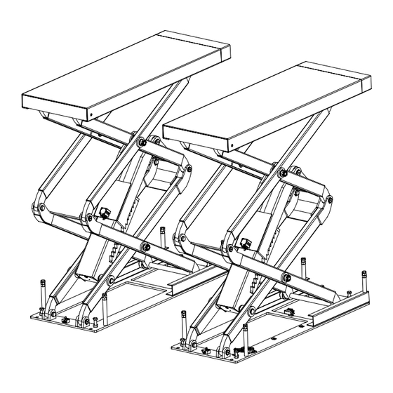
Page 8: Product Description
CHAPTER 4 - PRODUCT DESCRIPTION 4.1 LIFT DESCRIPTION (Ref. Figure 1) The flush mounted lift has been designed for the lifting of motor-vehicles for wheel alignment and maintenance. The maximum lifting weight is as specified on the serial plate. All mechanical frames, such as platforms, extensions, base frames and arms have been built in steel plate to make the frame stiff and strong while keeping a low weight The electro hydraulic operation is described in detail in chapter 8. -
Page 9: Technical Specification
CHAPTER 5 - TECHNICAL SPECIFICATION SIZE AND MAIN FEATURES (Ref. Figure 2) CAPACITY 3000KG Max. lifting height 2060mm Length of the platform 1540 - 1740 mm Width of platform 550mm Free width between platforms 800mm Overall length 1540mm Overall width 1900mm Lifting time 60 s... - Page 10 Figure 2 - LAYOUT Drive on 10 / 30 REV. 02...
- Page 11 HYDRUALIC POWER UNIT FIG. 3 – HYDRAULIC POWER UNIT Motor Emergency Maximum pressure valve hand pump Leveling cutoff cock Lowering N.C (normally close) solenoid valve Emergency Leveling cutoff cock lowering screw N.O (normally open) Pressre gauge Oil tank Use wear proof oil for hydraulic drive, in conformity with ISO 6743/4 rules (HM class). The oil with features similar to those shown in the table is recommended.
- Page 12 Figure 4 – HYDRAULIC PLAN Master hydraulic cylinder Lowering solenoid valve Slave hydraulic cylinder Lowering control valve Leveling cutoff cock (normally open) Motor Leveling cutoff cock (normally close) Gear pump Pressure gauge Emergency hand pump Non return valve Oil filter Maximum pressure valve Parachute valve 12 / 30...
- Page 13 Figure 5a – ELECTRIC DIAGRAM (380V/400V-3PH) Power switch Lifting button Motor 2.6KW 3PH Lowering button Overhead protector Final lowering button Transformer 63VA Beeper Contactor DC Max. lifting height limit switch Lowering solenoid valve Safety height limit switch Solenoid air valve 13 / 30 REV.
- Page 14 Figure 5b – ELECTRIC DIAGRAM (220V/230V-1PH) Power switch Lifting button Motor 2.2KW 1PH Lowering button Overhead protector Final lowering button Transformer 63VA Beeper Contactor DC Max. lifting height limit switch Lowering solenoid valve Safety height limit switch Solenoid air valve 14 / 30 REV.
- Page 15 Figure. 6 – PNEUMATIC PLAN Pneumatic cylinders Solenoid air valve Water separator and lubricator Compressed air supply 15 / 30 REV. 02...
-
Page 16: Safety
CHAPTER 6 – SAFETY Read this chapter carefully and completely because it contains important information for the safety of the operator and the person in charge of maintenance. The lift has been designed and built for lifting vehicles and making them stand above level in a closed area. - Page 17 PERSONNEL CRUSHING RISKS During lowering of runways and vehicles, personnel must not be within the area covered by the lowering trajectory. The operator must be sure no one is in danger before operating the lift. Fig. 7a Fig. 7c Fig. 7b BUMPING RISK When the lift is stopped at relatively low height for working, the risk of bumping against projecting parts...
- Page 18 RISKS RESULTING FROM IMPROPER LIGHTING Make sure all areas next to the lift are well and uniformly lit, according to local regulations. 6.10 RISKS OF BREAKING COMPONENT DURING OPERATION Materials and procedures, suitable for the designed parameters of the lift, have been used by the manufacturer to build a safe and reliable product.
-
Page 19: Installation
CHAPTER 7 – INSTALLATION Only skilled technicians, appointed by the manufacturer, or by authorized dealers, must be allowed to carry out installation. Serious damage to people and to the lift can be caused if installations are made by unskilled personnel. CHECKING FOR ROOM SUITABILITY The lift has been designed to be used in covered and sheltered places free of overhead obstructions. - Page 20 Figure 13 – PIT FOUNDATION PLAN 330mm 770mm 580mm 580mm Min.1600mm Drive up Min.400mm Pipe (inner dia.100) placed here Pipe (inner dia.100) Groove 100X100mm To control unit Specifications of the pit must be adhered to. Failure to do so could cause lift failure resulting in personal injury or death.
- Page 21 Figure 14 – HYDRAULIC CONNECTIONS Hydralic power unit Leveling cutoff cock (nomrally open) Leveling cutoff cock (nomrally close) Slave hydralic cylinder Master hydralic cylinder PNEUMATIC SYSTEM CONNECTION The pneumatic supply at site (to which the pneumatic system of the lift is connected) must be equipped with a servicing unit composed of water separator, lubricator and pressure reducer.
- Page 22 Figure 15 – PNEUMATIC CONNECTIONS To the water separator/lubricator Air block placed Pneumatic cylinders Solenoid air valve on each base MAKE ELECTRICAL HOOKUP TO HYDRAULIC POWER UNIT The hookup work must be carried out by a qualified electrician. Make sure that the power supply is right. Make sure the connection of the phases is right.
- Page 23 • Make sure the lift is connected to the ground • Make sure the working area is free from people and objects • Grease sliding seats of blocks placed under platforms and on bases • Verify that the control unit is powered •...
- Page 24 ANCHORING THE BASE FRAMES • Place the lift at a height about 1m; • Using the base frames as guide, drill each hole in the concrete approximately 120mm deep with the rotary hammer drill 16. To assure full holding power, do not ream the hole or allow drill to wobble;...
- Page 25 7.11 CHECKS LESS LOAD During this procedure, observe all operating components and check for proper installation and adjustment. DO NOT attempt to raise vehicle until a thorough operation check has been completed. Carry out two or three complete cycles of lowering and lifting and check: •...
-
Page 26: Operation And Use
CHAPTER 8 - OPERATION AND USE Never operate the lift with any person or equipment below. Never exceed the rate lifting capacity. Always ensure that the lift rests on the safety locks before any attempt is made to work on or near the vehicle. If an anchor bolt becomes loose or any component of the lift is found to be defective, DO NOT USE THE LIFT until repairs are made. - Page 27 LIFTING BUTTON UP (4) When pressed, the electric circuit for the lift operates the motor and hydraulic circuit to raise the lift LOWERING BUTTON DOWN-1 (5) When pressed, the lift descends to the safety height (400mm) FINAL LOWERING BUTTON DOWN-2 (6) When pressed with the lift at the safety height (400mm), it activates first the beeper and then the lift begins to lower to the minimum height.
- Page 28 MANUAL EMERGENCY LOWERING If there is no power or the control unit is damaged, lower the lift manually to its initial position as follows: • Padlock the power switch; • Operate the emergency hand pump (fig.19 - 1) to raise the lift a little bit to clear off the mechanical safeties;...
-
Page 29: Maintenance
CHAPTER 9 - MAINTENANCE Only trained personnel who knows how the lift works, must be allowed to service the lift. To service properly the lift, the following has to be carried out: • use only genuine spare parts as well as equipment suitable for the work required; •... -
Page 30: Troubleshooting
CHAPTER 10 – TROUBLESHOOTING A list of possible troubles and solutions is given below ROUBLE OSSIBLE AUSE OLUTION The main switch is not turned on Turn the switch on There is no power Check Power on to restore if necessary The electrical wires are Reconnect The lift does not work...
Need help?
Do you have a question about the STD-7330 and is the answer not in the manual?
Questions and answers