
Summary of Contents for BeLine 1000 Series
- Page 1 BeLine 1000/1100/RF1500 Series Cardlock Installation Guide BeLine Main (818)357-5980 www.belinelocks.com www.cardlockusa.com www.innlockcompany.com www.innlockco.com info@belinelocks.com...
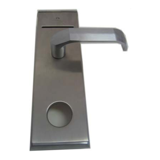
- Page 2 Unpacking the Cardlock The Cardlock is packed with the following items: EXTERIOR LOCK BODY (QUANTITY =1) INTERIOR LOCK BODY (QUANTITY =1) LOCK BODY SCREWS (QUANTITY =4)
- Page 3 MORTISE (QUANTITY =1) SQUARE MORTISE DRIVE (QUANTITY =2) SQUARE THUMBTURN DRIVE (QUANTITY =1) CYLINDER CAP AND KEY SET (QUANTITY =1) CYLINDER, KEYS AND CYLINDER CAP...
- Page 4 BATTERY TRAY (QUANTITY =1) FOR GENERAL OR PUBLIC ENTRANCE LOCKS, LITHIUM AA BATTERIES ARE RECOMMENDED. BATTERIES NOT INCLUDED STRIKE SET STRIKE CUP (QUANTITY =1) STRIKE PLATE (QUANTITY =1) STRIKE WOOD SCREWS (QUANTITY =2)
- Page 5 MORTISE FACE PLATE (QUATITY =1) MORTISE FACE PLATE SCREWS (QUANTITY =2) CARD READER (QUANTITY =1) ATTACHED TO INTERIOR LOCK BODY...
- Page 6 Template for Routing a Door BeLine strongly suggests that the installer purchase a metal template guide from BeLine for the door cutout process. For the actual mechanical dimensions for cutting the door refer to the document, Cardlock 1000 1100 1500 Template Available for download at www.cardlockusa.com, www.belinelocks.com,...
- Page 7 Step 1. Insert the Mortise and drive in wood screws Step 2. Hand screw the Cylinder into the Mortise KEY NOT TURNED When then key is inserted into the Cylinder and turned to unlock, the arm of the Cylinder needs enough room to rotate. When KEY TURNED A tight fit will result in a Cylinder over screwed into the Mortise.
- Page 8 Note: The Cylinder must be in the orientation shown above to allow the locking screw to secure the Cylinder (shown in Step 3.). Step 3. Securing the Cylinder Use a philips screwdriver to turn this screw. Turning the screw will extend it into the outer edge of the cylinder.
- Page 9 Step 5. Position Exterior Lock Body on Door Note: For easy slip on of the Exterior Lock Body the square shaft that was previously inserted into the Mortise must be aligned with the lever. Step 6. Route and connect the mortise cable to the Card Reader Step 7.
- Page 10 Step 9. Insert the Square Thumbturn Drive into the Mortise Step 10. Mount Interior Door Lock Body and lightly screw in Lock Body Screws Step 11. Attach Mortise Edge Faceplate...
- Page 11 Unfortunately you have the wrong part. The mortises are shipped preconfigured for Left Handed Outside swing (LO), Left Handed Inside swing (LI), Right Handed Outside swing (RO) or Right Handed Inside swing (RI). Consult with BeLine support before attempting to open and reconfigure the mortise. Opening the mortise with void the warranty on your lock.
- Page 12 The spring should typically lasts for many years until maintenance should be performed. The high spring can be purchased at any hardware store but BeLine recommends that it be purchased from BeLine to guarantee many years of usage.
- Page 13 Programming the Cardlock 1) Assure batteries are installed and the Battery Tray is connected. 2) Insert a TIME CARD. 3) Insert a Room Card with the room number of your choice. The Cardlock will have saved the room number and time. The battery must be connected from this point on to maintain an accurate time.
Need help?
Do you have a question about the 1000 Series and is the answer not in the manual?
Questions and answers