Table of Contents
Advertisement
User manual
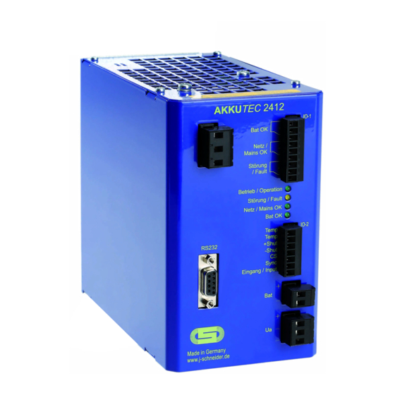
AKKUTEC 2412 VdS
1. General ...................................................................................................................... 2
1.1
1.2
2
Transportation And Storage ..................................................................................... 3
3
Installation And Connection ..................................................................................... 3
3.1
Installation
3.2
3.3
3.4
3.5
3.6
3.7
4
Start-Up ..................................................................................................................... 9
4.1
5
Operation .................................................................................................................. 9
5.1
Mains operation
5.2
Back-up operation
5.3
5.4
5.5
5.6
Temperature Tracking (optional)
5.7
5.8
Acoustic alarm transmitter (optional)
6
Master/Slave-Operation At Parallel Connection ..................................................... 11
6.1
Connection at Master/ Slave-operation
6.2
6.3
Shutdown at Master/Slave-operation
6.4
7
Servicing .................................................................................................................. 13
7.1
7.2
8
Decommissioning .................................................................................................... 14
9
Disposal ................................................................................................................... 14
10 Norms and regulations ........................................................................................... 14
11 Technical Data ......................................................................................................... 15
12 Accessories ............................................................................................................. 16
Document
0812G01B02-160422.docx
J. Schneider Elektrotechnik GmbH
Helmholtzstraße13, 77652 Offenburg · Postfach 2327, 77613 Offenburg · Werner-von-Siemens-Straße 12, 77656 Offenburg
Tel +49 (0) 781 206 0 · Fax +49 (0) 781 253 18 ·
Geschäftsführer:
Dipl.-Betriebswirtin (BA) Bettina Schneider · Dipl.-Wirt,-Ing. (FH) Rolf Anti · UST-Ident-Nr. DE142532740
NBPA0812G01***
VdS-Nummer G209169
info@j-schneider.de
·
www.j-schneider.de
DC-USV
0786-CPD-20873
· Amtsgericht Freiburg HRB 470458
page
page 1 / 16
Advertisement
Table of Contents

Summary of Contents for J.Schneider AKKUTEC 2412 VdS
- Page 1 User manual AKKUTEC 2412 VdS DC-USV NBPA0812G01*** VdS-Nummer G209169 0786-CPD-20873 page 1. General ........................2 General safety notes Short description Transportation and storage ..................3 Installation and connection ..................3 Installation Connection Connection lead accumulator Connection of mains voltage Connection load...
- Page 2 User manual AKKUTEC 2412 VdS 1. General The accumulator buffered DC supply guarantees a safe backup of the DC supply in case of a mains failure. Every other use is strictly excluded. The operating instructions must be read prior to use or installation; all instructions have to be considered! Commissioning and maintenance may only be performed by qualified specialist personnel.
- Page 3 User manual AKKUTEC 2412 VdS Short description The accumulator buffered DC supply works according to the standby parallel principle and guarantees, in con- nection with a lead accumulator and for a certain time interval, a safe upkeep of the DC supply in case of a mains failure.
- Page 4 User manual AKKUTEC 2412 VdS Connection Prior to connection, the DC voltage supply values must be checked for compliance with the values given on the label. Connect according to the designations of the connection terminals (see terminal assignment, sec- tion 3.7 Circuit diagram). Not used connection screws must be tightened.
- Page 5 User manual AKKUTEC 2412 VdS Connection lead accumulator Capacity Max. load current Rated current during charging (ImaxA) of the power supply (ImaxB) 2x lead accumulator 12 V / 26 Ah 10.70 A 2x lead accumulator 12 V / 38 Ah 10.10 A...
- Page 6 User manual AKKUTEC 2412 VdS Connection of mains voltage The input voltage of the external energy supply must correspond to the mains voltage at the distribution. The mains voltage must be disconnected and secured against unintended powering up. The voltage-free mains cable must be connected to the mains connection terminal provided for this, taking into account the phase.
- Page 7 User manual AKKUTEC 2412 VdS DC-Output Batt Accumulator connection DC/DC Control IO-1 Control 30V DC/ Bat OK 0,5A Mains 30V DC/ Netz / Mains OK 0,5A 30V DC/ µP Störung / Fault 0,5A Betrieb / Operation Störung / Fault Netz / Mains OK...
- Page 8 User manual AKKUTEC 2412 VdS Fuse board Fuse boards can be plugged in directly into the power supply or separately mounted on T-rail. Each output is separately monitored. In case of fuse blow, the corresponding LED goes out and a general error signalizes the fuse blow to the AKKUTEC.
- Page 9 User manual AKKUTEC 2412 VdS Start-Up The power supply is switched on by the activation of the mains voltage (230 V AC). DANGER Check the correctness of the connections prior to the first activation! Establish electrical connections only in de-energized status! In case of non-observance, touching live parts can result in death or serious injury.
- Page 10 (See section When the AKKUTEC 2412 VdS is delivered it is configurated for three different accumulator dimen- sions. Herewith the limiting value for the measurement of the internal resistance is adjusted as follows: 7 Ah -18 Ah 225 mΩ...
- Page 11 User manual AKKUTEC 2412 VdS Shut-Down Buffer operation can be interrupted early in order to avoid a discharge of the lead accumulator up to the deep discharge limit. This can be done by connecting a +24 V DC control voltage to the terminal 3 (+Shut) and 4 (- Shut) of the terminal strip IO-2.
- Page 12 User manual AKKUTEC 2412 VdS Signalisation at Master/Slave-operation: The signal contacts for mains failure of the Master and the Slave must be connected in series to detect an error signal from both units. At the Slave the signal and the signal contact Bat OK are not active. (neither on the contact Fault, the master takes over this function completly).
- Page 13 User manual AKKUTEC 2412 VdS Servicing In order to ensure the buffering ability of the power supply, the lead accumulators should be tested for their buffering capability in regular intervals of 3 to 6 months. The housing must be cleaned at least once per year depending on the degree of contamination.
- Page 14 User manual AKKUTEC 2412 VdS Decommissioning The decommissioning is performed by the removing of the mains voltage. In order to avoid subsequent buffer- ing, the accumulator must be interrupted by activating the Shut-Down-signal or by removing the accumulator fuse. The LED Mains-OK and the Error must go out in this case.
- Page 15 User manual AKKUTEC 2412 VdS 11 Technical Data Nominal input voltage 230 V AC (±15%) 195.5 V … 264.5 V Input voltage range for charging operation 47 Hz … 63 Hz Nominal frequency Power consumption 380 VA Self current consumption 75 mA @ 24 V Max.
- Page 16 User manual AKKUTEC 2412 VdS 12 Accessories In application cases with frequent and strong temperature variations, the charging voltage should be adjusted in order to avoid accumulator overload (danger of gassing!). In the same way, a temperature adjustment should be ensured in particular in case of very low ambient temperatures (Tu < 15 °C) in order to ensure suffi- cient accumulator charge.
Need help?
Do you have a question about the AKKUTEC 2412 VdS and is the answer not in the manual?
Questions and answers