Table of Contents
Advertisement
Quick Links
Advertisement
Table of Contents
Troubleshooting

Subscribe to Our Youtube Channel
Summary of Contents for Hyd-Mech DM8
- Page 1 USE AND MAINTENANCE MANUAL DM 8 YEAR OF MANUFACTURE: ______________...
-
Page 3: Table Of Contents
Introduction and technical specifications ..... . . 1---1 Foreword ............1---1 Presentation of the machine . - Page 4 CCS (Cut Control System) functioning cycle ......5---10 Angled cuts ............5---11 Angled cuts 45˚...
- Page 5 Blade guide plates ..........7---9 Blade .
-
Page 7: Introduction And Technical Specifications
Introduction and technical specifications Foreword This work tool has been designed to satisfy the wide range of cutting needs of a modern workshop with simplicity and reliability, while at the same time comply- ing with all EEC safety standards. The DM 8 is structurally rigid, silent and safe: it produces a minimum of waste (1.2 mm = 0.05 in.) while its great versatility makes it suitable for cutting various materials such as stainless steel light alloys, aluminium, copper and bronze at high speed and with high precision. -
Page 8: Presentation Of The Machine
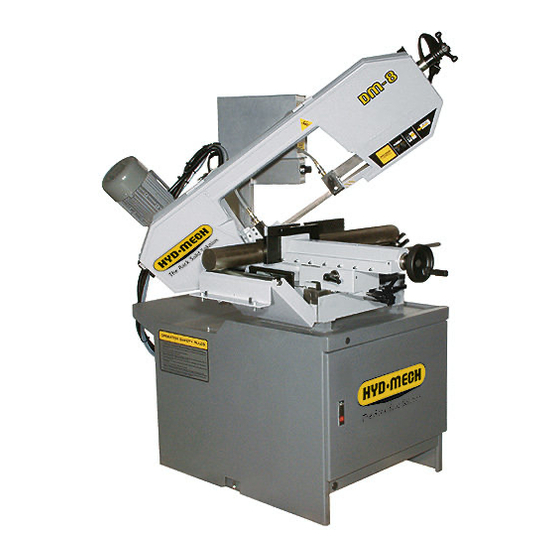
MEP S.p.A. Presentation of the machine Functioning is completely manual: the operator, after having checked the workpiece in the vice, grips the control lever and presses the bandsaw start microswitch; with a downwards movement, the material is cut to the preset length;... - Page 9 Version 24DM All models can be equipped with the Inverter, an optional device, which offers Warning a range of speeds comprised between 20 and 90 mt/min. (from 6.23 to 28.04 ft./min). As the machine is predisposed for the Inverter, it can be installed by the client or factory pre--installed on request made during the ordering proce- dure.
-
Page 10: Dimensions 1
MEP S.p.A. When choosing the cutting tool, if its dimensions do not correspond to those Attention included in the ”Rated size” section, check that the dimensions at least fall within the admissible max/min specifications. RATED ELECTRICAL POWER Spindle motor 2.5/2 Lubricant/coolant fluid electropump motor Max electrical power rating WORKING PRESSURE MODEL MA (Automatic Vice) - Page 11 Version 24DM The machine is supplied with a 2/4 pole three phase motor giving 2 band saw Warning speeds: -- 1ª speed (4 poles) = 36 mt/min (11.21 ft./min) -- 2ª speed (2 poles)= 72 mt/min (22.43 ft./min); The OPTIONAL 4/8 pole motor gives speeds of 36/18 mt./min. (11.21 / 5.61 ft./min).
- Page 12 MEP S.p.A. ELECTROPUMP MOTOR Single phase; Frequency 60 Hz. Voltage (Volts) Absorption (Amps) Power (HP) Delivery rate Head (mt.) lt/min 0.22 3380 3380 0.16 3380 Protection rating IP 55. Conforming to CEI norms, publication: IEC 34 of 01/07/1985. CUTTING CAPACITY Ø...
-
Page 13: Dimensions
Version 24DM Dimensions MACHINE INSTALLED Work table height 34.25 Weight 6.70 18.50 16.14 27.56 35.43 21.65 1800 70.87 Introduction and technical specifications 1- -7... -
Page 14: Functional Parts
Functional parts DM 8 Model In order for the user to move towards a full understanding of how the machine works, which is described in detail in the chapter DESCRIPTION OF MA- CHINE OPERATION, this chapter deals with the main units and their locations. CONTROL PANEL CUTTING... -
Page 15: Cutting Head
MEP S.p.A. Cutting head The cutting head is the unit that cuts the material. It consists of a cast iron head on which the following are mounted: the band saw, the blade guide components, the blade tensioner components, the transmission box and the spindle motor. The cutting head is limited in its movements by the joint on the work table, and its cutting stroke is manually guided by the operator. -
Page 16: Control Panel
Version 24DM Control panel The control panel has a protection rating of IP 54 and contains the electrical equipment. Access is gained by removing the screws fastening a safety panel, while the operator’s safety is guaranteed by a key---operated safety switch, designed to prevent any intentional interference with the unit. -
Page 17: Base
MEP S.p.A. Base On opening the door in the base, you will find the air treatment unit (optional extra only on versions with MA automatic vice) and the drawer with the coolant, complete with electric pump. Electric pump Lubricant/coolant tank 2- -4 Use and maintenance manual DM 8... -
Page 18: Safety And Accident Prevention
Safety and accident prevention The DM 8 has been designed and produced in accordance with European standards. For the correct use of the machine we recommend that the instruc- tions contained in this chapter are carefully followed. Use of the machine The DM 8 band saw cutting machine is intended exclusively for cutting metallic materials, ferrous or non---ferrous, in section or solid. -
Page 19: General Recommendations
MEP S.p.A. General recommendations LIGHTING Insufficient lighting for the types of operation envisaged could constitute a safety hazard for the persons concerned. For this reason, the machine user must provide lighting in the working area sufficient to eliminate all shadowy areas while also avoiding any blinding light concentrations. -
Page 20: Recommendations To The Operator
Version 24DM Recommendations to the operator Always wear proper goggles or protective glasses. Do not use the machine without the guards in place. Do not allow hands to encroach on the cutting zone while the machine is operating or still in motion. Do not wear oversize clothing with long sleeves, oversize gloves, brace- lets, necklaces or any other object that may become entangled in the ma- chine during working;... - Page 21 MEP S.p.A. The operator must not perform any risky operations or operations not required for the machining operation under way (e.g. remove swarf or metal shavings from the machine while cutting). Remove equipment, tools or any other objects from the cutting zone; al- ways keep the working area as clean as possible.
-
Page 22: Machine Safety Devices
Version 24DM Warning: if the blade jams in the cut, press the emergency stop push--- button immediately. If this does not free the blade, slowly loosen the vice, remove the piece and check the blade or blade teeth for breakage. Replace the blade if necessary. -
Page 23: Safety Protection Against Accidental Contact With The Blade
MEP S.p.A. Safety Protection against accidental contact with the blade 1. Metal guard screwed to the rear blade guide head (machine side); 2. Metal guard screwed to the front blade guide head (operator side); 3. front head sliding support: when the head is at maximum aperture, the support ensures that the blade is covered, leaving free only the part of the blade engaged in the actual cutting, in accordance with Presidential Decree no. -
Page 24: Emergency Devices
Version 24DM Emergency devices In accordance with IEC 204---1Standard: = Chapter 5 Section 6 Sub---section 1 ”Emergency stop device”: «the emergency stop device immediately stops all dangerous and other functions of the machine.» = Chapter 6 Section 2 Sub---section 4 Point 7 ”Protective guards”: «the removal of protective guards designed to prevent access to dangerous parts or zones causes the machine to stop immediately;... -
Page 25: Machine Noise Level
MEP S.p.A. Machine noise level Noise can cause hearing damage and represents one of the problems dealt with by many countries by adopting their own regulations. In accordance with the EEC Machine Directive no. 98/37/CE we list the standards that specify noise levels for machine tools. -
Page 26: Electromagnetic Compatibility
Version 24DM Electromagnetic compatibility As from 1 January 1996 all electrical and electronic appliances bearing the CE marking that are sold on the European market must conform to Directive 89/336/EEC and decree law no. 476/92 concerning electromagnetic compatibility, i.e. the compatibility of electrical/electronic devices and systems with the electromagnetic environment in which they are located. -
Page 27: Immunity
MEP S.p.A. Immunity = EN 50082- -2 (1995) Electromagnetic Compatibility - - Generic standard on immuni- ty. Part 2: Industrial Environment. The EUT is deemed to fulfil the immunity requirements without testing, because it contains no electonic control circuitry. 3- -10 Use and maintenance manual DM 8... -
Page 28: Machine Installation
Machine installation Packaging and storage MEP S.p.A. use packing materials that guarantee the integrity and protection of the machine during its transport to the customer. The type of packing differs according to the size, weight and destination. Therefore the customer will receive the machine in one of two following ways: ¡... - Page 29 MEP S.p.A. Do not handle the packed machine using slings. Attention When storing, machines palletized and shrink--wrapped must not be stacked Attention two high, and machines pallettized and crated must not be stacked three high. To install the machine, first remove the packing, paying particular attention not to cut any electric wires or hydraulic hoses;...
- Page 30 Version 24DM 2. remove nails and lower walls; ¡ © © © © 3. remove heat---shrink covering; 4. remove the straps; 5. remove nails from pallet securing planks and remove planks; 6. remove the front panel and insert fork tines. ¢...
-
Page 31: Anchoring The Machine
MEP S.p.A. To locate the machine in the workplace, the machine dimensions and necessary operator working space, including the spaces laid down in safety standards, must be taken into account. Anchoring the machine The base of the machine is anchored to the floor by two permanent studs located on the sides of the base. -
Page 32: Check List
Version 24DM Check list Before starting installation, check that all the accessories, whether standard or optional, supplied with the machine are present. The basic version of the DM 8 2---SPEED machine is supplied complete with: - base with large swarf collection drawer, removable coolant tank and electro- pump for band saw lubrication/cooling;... -
Page 33: Balancing The Cutting Head
MEP S.p.A. - K60/K100 roller table for discharge side, 3000 mm (118.11 in.); - K60/K100 roller table for discharge side, 4500 mm (177.16 in.); - K60/K100 roller table for discharge side, 6000 mm (236.22 in.); - 5 litres of emulsible oil. Balancing the cutting head Before making the electrical and pneumatic connections (MA version), the head return springs must be tensioned to balance the cutting head weight. -
Page 34: Connection To The Power Supply
Version 24DM Connection to the power supply Before connecting the machine to the power supply, check that the socket is not series---connected with other machines. This requirement is fundamental for efficient operation of the machine. To connect the machine to the power supply, proceed as follows: "... - Page 35 MEP S.p.A. " make sure the cover is properly closed: at the back of the cutting head there is a bayonet limiter for correct cover closure; " make sure that the machine is not in emergency state (red mushroom button released);...
-
Page 36: Description Of Machine Operation
Description of machine operation This chapter analyses all the machine functions. We begin with a description of the pushbuttons and other components on the control panel. Description of the control panel The components of the DM 8 control panel are shown in the diagram below. Each arrow has a number which corresponds to the descriptions that follow. - Page 37 MEP S.p.A. 2 - - PREDISPOSITION FOR INVERTER (OPTIONAL) Selects the blade cutting speed range: from 20 to 45 mt/min. (from 6.23 to 14.02 in.) for the 1st speed and from 35 to 90 mt/min. (from 10.90 to 28.04 ft./min) for the second speed.
-
Page 38: Basic Instructions For Carrying Out A Cutting Operation Cycle
Version 24DM HEAD CONTROL LEVER MICROSWITCH The grip of the manual head control lever incorporates a microswitch for manual control of the blade motor. Microswitch Operating lever The microswitch is enabled when the machine is not in emergency state. In compliance with the relevant existing standards, voltage is 24V and the micro- switch is installed in a housing (blue knob) sealed against external agents such as dust or moisture, with a protection rating of IP 55. -
Page 39: Clamping The Work Piece In The Vice
MEP S.p.A. Clamping the work piece in the vice In the basic version, the work piece is clamped in the vice by rotating the opening/closing handwheel (in a clockwise/anticlockwise direction), as shown: " each time the vice is closed make certain that the work piece is solidly clamped. -
Page 40: Rapid Opening/Closing Of The Vice
Version 24DM Rapid opening/closing of the vice Using a simple device the vice can be slid forwards and backwards to accelerate vice opening and closing operations. " Grip the lever as indicated in the photograph and rotate in a clockwise direc- tion: the vice is free to slide forwards and backwards into the desired position. -
Page 41: Width Of Cut
MEP S.p.A. Width of cut In compliance with the existing standards, the machine is provided with guards covering the blade throughout its length except for the tract which is to be used to make a cut. The width of the cut should be determined on the basis of the longitudinal section of the workpiece, in order to leave free only the part of the saw which will perform the cut. -
Page 42: Preliminary Check List For Cutting Operation
Version 24DM Preliminary check list for cutting operation To guarantee complete safety during cutting cycles, the operator should work through a check list of the entire apparatus, checking: " blade tension; " that the blade guide head bracket is locked in the correct position; "... - Page 43 MEP S.p.A. " Grip the head control lever and start the blade rotating by pressing the micro- switch on the handgrip; the downstroke speed of the head is manually con- trolled by the operator. " The motor starts up and sets the blade in rotary motion; the lubricant/coolant pump starts up at the same time.
- Page 44 Version 24DM " At the end of the cutting operation, the head can be raised. " Remove the piece from the vice; in the MA version the vice is opened using the open/close button, or by manually turning the vice handwheel. If the machine is equipped with the Cut Control System, make sure that the Warning function selector switch is positioned on Manual and that the head return...
-
Page 45: Ccs (Cut Control System) Functioning Cycle
MEP S.p.A. CCS (Cut Control System) functioning cycle The Cut Control System enables both a Manual and a Semiautomatic/Dynamic work cycle to be performed. Sequence of operations for carrying out a cut in Semiautomatic/Dynamic mode: " power up the machine by pressing the reset switch. "... -
Page 46: Angled Cuts
Version 24DM " Grip the head control lever and move the blade in the proximity of the mate- rial to be cut: when you reach a distance of approx. 10 mm select function type: Semi---automatic or Dynamic and then press microswitch on the hand- grip to start up blade rotation "... - Page 47 MEP S.p.A. " Pull the eccentric pin knob towards you (0˚ reference stop) and rotate slightly to raise it. The 0, 45 and 60˚ reference stops for cuts to the left and the 45˚ reference Warning stop for cuts to the right facilitate rapid head positioning during turntable rota- tion.
-
Page 48: Angled Cuts 60˚ To The Left
Version 24DM Angled cuts 60˚ to the left " Undo the bush on the 45˚ left reference stop, as illustrated in the figure be- low, using a 36 mm wrench. " Slacken the turntable lock/release lever. " Pull the eccentric pin knob towards you (0˚reference stop) and rotate slightly to raise it. -
Page 49: Angled Cuts 45˚To The Right
MEP S.p.A. Angled cuts 45˚to the right " Make sure the vice is positioned to the right of the 0˚ cutting slot. " Slacken the locking lever as shown in the figure below. " Position the vice to the right and lock the lever. When positioning the vice to the left or right, make sure the moving jaw is be- Attention yond the 0˚cutting slot to avoid any risk of collision with the blade downstroke. -
Page 50: Diagrams, Exploded Views And Replace
Diagrams, exploded views and replace-- ment parts This chapter contains functional diagrams and exploded views of the DM 8, including the MA version. This document is intended to help in identifying the location of the various components making up the machine, giving information useful in carrying out repair and maintenance operations;... -
Page 51: How To Read The Wiring Diagrams
MEP S.p.A. How to read the wiring diagrams With the introduction of the new standardised wiring diagrams, the following gives an illustration of the way in which they have been drawn up. Each sheet of the project contains a box which gives the following information: The numbers indicate the co- lumns into which the entire dra- wing is divided... - Page 52 Version 24DM Each component in the wiring diagram is identified by a unique alphanumeric identification code, in com- pliance with regulations: The wire is identified by the code --W4 This symbol identifies the wire with its relative number and co- lour MARIO ROSSI These symbols, known as potentials, are used to provi-...
- Page 53 MEP S.p.A. 2. wires list (list of all wires) with the following information: - in- -house article code; - identification code; - description - section of wire (mm - colour of wire; - start: indicates the component (identification code and contact number) at which the wire starts; - end: indicates the component (identification code and contact number) at which the wire ends;...
- Page 54 Version 24DM LETTER TYPE OF COMPONENT EXAMPLES IDENTIFICATION OF THE COMPONENT Rotating generators Crystal oscillators Accumulator battery Generators, feeders Rotating or static frequen- cy converter Power feeder Buzzer Signaling Devices Optical signal, indicator light device Instant all or nothing relays or instant contactors Bistable relays or interde- pendent contactors...
- Page 55 MEP S.p.A. LETTER TYPE OF COMPONENT EXAMPLES IDENTIFICATION OF THE COMPONENT Current transformer Control circuit supply tran- sformer Transformers Power transformer Magnetic stabiliser Voltage transformer Discriminator Demodulator Frequency converter Coder Modulators, converters Converter Inverter Telegraphic repeater Electronic pipe Gas discharge pipe Electronic pipes, semiconduc- Diode tors...
-
Page 56: Standard Version Electrical Diagram 208V (Csa Standard)
Version 24DM Standard version electrical diagram 208V (CSA standard) Diagrams, exploded views and replacement parts 6- -7... - Page 57 MEP S.p.A. 6- -8 Use and maintenance manual DM 8...
- Page 58 Version 24DM Diagrams, exploded views and replacement parts 6- -9...
- Page 59 MEP S.p.A. 6- -10 Use and maintenance manual DM 8...
- Page 60 Version 24DM Diagrams, exploded views and replacement parts 6- -11...
- Page 61 MEP S.p.A. 6- -12 Use and maintenance manual DM 8...
- Page 62 Version 24DM Diagrams, exploded views and replacement parts 6- -13...
- Page 63 MEP S.p.A. 6- -14 Use and maintenance manual DM 8...
-
Page 64: Standard Version Electrical Diagram 240V (Csa Standard)
Version 24DM Standard version electrical diagram 240V (CSA standard) Diagrams, exploded views and replacement parts 6- -15... - Page 65 MEP S.p.A. 6- -16 Use and maintenance manual DM 8...
- Page 66 Version 24DM Diagrams, exploded views and replacement parts 6- -17...
- Page 67 MEP S.p.A. 6- -18 Use and maintenance manual DM 8...
- Page 68 Version 24DM Diagrams, exploded views and replacement parts 6- -19...
- Page 69 MEP S.p.A. 6- -20 Use and maintenance manual DM 8...
- Page 70 Version 24DM Diagrams, exploded views and replacement parts 6- -21...
- Page 71 MEP S.p.A. 6- -22 Use and maintenance manual DM 8...
-
Page 72: Standard Version Electrical Diagram 575V (Csa Standard)
Version 24DM Standard version electrical diagram 575V (CSA standard) Diagrams, exploded views and replacement parts 6- -23... - Page 73 MEP S.p.A. 6- -24 Use and maintenance manual DM 8...
-
Page 74: Exploded Views 6
Version 24DM Diagrams, exploded views and replacement parts 6- -25... - Page 75 MEP S.p.A. 6- -26 Use and maintenance manual DM 8...
- Page 76 Version 24DM Diagrams, exploded views and replacement parts 6- -27...
- Page 77 MEP S.p.A. 6- -28 Use and maintenance manual DM 8...
- Page 78 Version 24DM Diagrams, exploded views and replacement parts 6- -29...
- Page 79 MEP S.p.A. 6- -30 Use and maintenance manual DM 8...
-
Page 80: Standard Version Electrical Diagram 220V Single
Version 24DM Standard version electrical diagram 220V Single- -Phase (CSA standard) Diagrams, exploded views and replacement parts 6- -31... - Page 81 MEP S.p.A. 6- -32 Use and maintenance manual DM 8...
- Page 82 Version 24DM Diagrams, exploded views and replacement parts 6- -33...
- Page 83 MEP S.p.A. 6- -34 Use and maintenance manual DM 8...
- Page 84 Version 24DM Diagrams, exploded views and replacement parts 6- -35...
- Page 85 MEP S.p.A. 6- -36 Use and maintenance manual DM 8...
- Page 86 Version 24DM Diagrams, exploded views and replacement parts 6- -37...
- Page 87 MEP S.p.A. 6- -38 Use and maintenance manual DM 8...
- Page 88 Version 24DM Diagrams, exploded views and replacement parts 6- -39...
-
Page 89: Exploded Views
MEP S.p.A. Exploded views This part of the manual contains detailed exploded views of the machine which can help to gain a deeper knowledge of how it is made. Motor assembly 6- -40 Use and maintenance manual DM 8... - Page 90 Version 24DM SPARE PARTS Code Description U.of M. Quantity 001.4254 DRIVING PULLEY 1,000 007.4012 REDUCTOR SHAFT 1,000 010.0355 SELF--LOCKING RING NUT 25X1,5 1,000 010.7111 8 X 7 X 32 KEY 1,000 010.7112 8 X 7 X 35 KEY 1,000 010.7604 0 8 WASHER 4,000 010.7605...
-
Page 91: Front Flywheel Assembly
MEP S.p.A. Front flywheel assembly 6- -42 Use and maintenance manual DM 8... - Page 92 Version 24DM SPARE PARTS Code Description U.of M. Quantity 001.4018 BLADE TENSIONER SLIDE 1,000 001.4208 HEAD GUIDE LOCKING BRACKET 1,000 001.4255 IDLER PULLEY 1,000 001.4260 IDLER PULLEY SECTION BOW 1,000 007.3811 HANDWHEEL SPACER 1,000 007.3825 BLADE TENSIONING REGULATING PIN 1,000 007.3843 FREE FLYWHEEL SHAFT 1,000...
-
Page 93: Motor Flywheel Assembly
MEP S.p.A. Motor flywheel assembly 6- -44 Use and maintenance manual DM 8... - Page 94 Version 24DM SPARE PARTS Code Description U.of M. Quantity 001.4258 DRIVING PULLEY SECTION BOW 1,000 007.3812 HEAD PIVOT BEARING SPACER 1,000 007.3813 BOW SPACER 1,000 007.3822 HEAD PIVOT SUPPORT PIN 1,000 007.4005 60› REAR BLADE GUIDE HEAD BRACKET 1,000 007.4057 LIMIT STOP BUSHING 1,000 010.0356...
-
Page 95: Cutting Head Cover
MEP S.p.A. Cutting head cover 6- -46 Use and maintenance manual DM 8... - Page 96 Version 24DM SPARE PARTS Code Description U.of M. Quantity 010.7601 0 4 WASHER 2,000 010.7850 TCEI 4 X 8 SCREW 2,000 010.7990 TSPEI 4 X 8 SCREW 2,000 010.7993 TSPEI 5 X 12 SCREW 4,000 016.1102 BOW COVER 1,000 016.1224 SAFETY COVER SWITCH FIX PLATE 1,000 034.1107...
-
Page 97: Vice Assembly
MEP S.p.A. Vice assembly 6- -48 Use and maintenance manual DM 8... - Page 98 Version 24DM SPARE PARTS Code Description U.of M. Quantity 001.4007 SLIDING VICE 1,000 001.4037 VICE SUPPORT 1,000 007.3824 QUICK CLAMPING VICE LOCKING PIN 1,000 007.3839 VICE GIB 1,000 007.3891 VICE SCREW BUSHING 1,000 007.4058 CAM BUSHING 1,000 007.4081 UNLOCKING LOWER VICE PINION 1,000 010.0211 525X24TPN VICE SCREW...
-
Page 99: Base Assembly
MEP S.p.A. Base assembly 6- -50 Use and maintenance manual DM 8... - Page 100 Version 24DM SPARE PARTS Code Description U.of M. Quantity 010.1803 BASE DOOR CLOSURE 1,000 010.1881 BASE DOOR HINGE 2,000 010.7208 M16 SCREW NUT 1,000 010.7603 0 6 WASHER 2,000 010.7606 0 12 WASHER 2,000 010.7868 TCEI 6 X 12 SCREW 2,000 010.7871 TCEI 6 X 20 SCREW...
-
Page 101: Control Panel
MEP S.p.A. Control panel 6- -52 Use and maintenance manual DM 8... - Page 102 Version 24DM SPARE PARTS Code Description U.of M. Quantity 010.7603 0 6 WASHER 2,000 010.7604 0 8 WASHER 4,000 010.7830 5 X 10 BUTTON SCREW 14,000 010.7870 TCEI 6 X 16 SCREW 2,000 010.7893 TCEI 8 X 20 SCREW 4,000 016.0708 LVD COMMAND PANEL 1,000...
-
Page 103: Handgrip
MEP S.p.A. Handgrip 6- -54 Use and maintenance manual DM 8... - Page 104 Version 24DM SPARE PARTS Code Description U.of M. Quantity 010.0928 SPRING FOR MEP DIS.1189559 HANDLE 1,000 010.7409 8 X 10 CYLINDRICAL POINT VCE GRUB SCREW 1,000 010.7700 CYLINDRICAL PIN DIA M. 4 X 24 1,000 010.7800 2,9 X 15 SELF--THREADING SCREW 3,000 022.0515 MICROSWITCH V--21--1C6...
-
Page 105: Reduction Gear
MEP S.p.A. Reduction gear 6- -56 Use and maintenance manual DM 8... - Page 106 Version 24DM SPARE PARTS Code Description U.of M. Quantity 001.4261 62 REDUCTOR GEAR HOUSING 1,000 001.4262 62 REDUCTOR GEAR PLUG 1,000 001.4625 REDUCTOR GEAR MOTOR FLANGE 1,000 001.4627 REDUCTOR GEAR BEARING COVER 1,000 007.4008 62 REDUCTOR SPINDLE SHAFT 1,000 010.0352 SELF--LOCKING RING NUT 35X1,5 2,000 010.7005...
-
Page 107: Fixed Work Table And Turntable
MEP S.p.A. Fixed work table and turntable 6- -58 Use and maintenance manual DM 8... - Page 108 Version 24DM SPARE PARTS Code Description U.of M. Quantity 001.3111 STOP SPACER 1,000 001.4701 FIXED PLATFORM 1,000 001.4702 TURNTABLE 1,000 002.0101 FIXED LEFT VICE JAW 1,000 002.0102 FIXED RIGHT VICE JAW 1,000 007.3819 CENTRE PIN 1,000 007.3827 BUSHING FOR STOP 1,000 007.3895 BUSH 0 38 FOR ROLLER...
-
Page 109: Optional Cut Control System
MEP S.p.A. Optional Cut Control System 6- -60 Use and maintenance manual DM 8... - Page 110 Version 24DM SPARE PARTS Code Description U.of M. Quantity 007.4209 CYLINDER EXTENSION 1,000 010.0914 HEAD RETURNING ACTION SPRING 1,000 010.1103 16 X 1,5 RATCHET FORK 1,000 010.1463 CYLINDER SUPPORT BRACKET 1,000 010.1464 SPRING BRACKET COUPLER 1,000 010.1502 CUT CONTROL FIX BRACKET 1,000 010.1656 PIN TO SPRING SLEEVE 1,000...
-
Page 111: Supplementary Pneumatic Vice
MEP S.p.A. Supplementary pneumatic vice 6- -62 Use and maintenance manual DM 8... - Page 112 Versione 24DM SPARE PARTS Code Description U.of M. Quantity 010.0244 576X24 VICE SCREW 1,000 010.7427 8 X 12 CYLINDRICAL POINT VCE GRUB SCREW 1,000 010.7454 8 X 8 CONICAL POINT VCE GRUB SCREW 1,000 010.7603 0 6 WASHER 2,000 010.7868 TCEI 6 X 12 SCREW 2,000 010.7893 TCEI 8 X 20 SCREW 1,000...
-
Page 114: Adjustments
Adjustments This chapter illustrates the regulations and adjustments of the mechanical systems (pneumatic systems in the MA version) for correct use of DM 8 G. These instructions will enable you to ”customise” your machine to suit the type of cuts you want, optimising the time required to complete them. -
Page 115: Topping Up And Bleeding The Cylinder (Cut Control System)
MEP S.p.A. Topping up and bleeding the cylinder (Cut Control System) Topping up the head cylinder This operation is done when the oil in the hydraulic cylinder compensator tank is low. First the cylinder head is brought to the HUL (Head Up Limiter) position so that the oil level in the compensation tank (see photograph below) can be checked using the rod. -
Page 116: Bleeding The Head Cylinder
Version 24DM " using a manual pump, loaded with MOBIL DTE 11 oil (or equivalent --- see table in Chapter 8), top up until the upper rod groove exits, as illustrated above. Bleeding the head cylinder Accumulations of air inside the hydraulic circuit cause the head to stutter in down phase. -
Page 117: Vice
MEP S.p.A. Vice Vice play adjustment Any play that develops between the slideway and the slide gib on the vice must be compensated by adjusting the grub screws regulating the distance between the gib and the lead screw, proceeding as follows: "... -
Page 118: Cutting Head
Version 24DM " at the end of the operation, use the handwheel to move the slideway back and forth, identifying the zones where the grub screws exert greater pressure on the gib; " repeat the adjustment operation if necessary. Cutting head Blade tensioner slide play adjustment To reduce the play which develops over a period of time between the blade tensioner slide and the slide gibs, the grub screws separating the gibs from the... -
Page 119: Blade Tensioning Unit
MEP S.p.A. " if there is play, tighten the grub screws; if there is friction rubbing, loosen the grub screws. Blade tensioning unit The blade tensioning unit on these models is hydraulic. This means that the oil level in the tensioning cylinder must be replenished whenever needed to ensure correct operation of the unit. - Page 120 Version 24DM " Pull out the piston, if necessary, using a pair of pliers, until it protrudes 44 mm from the cylinder. " Top up with AGIP ATF DEXRON oil or one with similar characteristics using a funnel. " Screw on the filler cap. "...
-
Page 121: Cutting Head Stroke
MEP S.p.A. Cutting head stroke During the cutting cycle the cutting head stroke is limited by the HUL (Head Upstroke Limit) and HDL (Head Downstroke Limit), set electronically on the control panel, as described on Page 5. The cutting head has a mechanical limiting switch that determines its downstroke: "... -
Page 122: Blade Guide Parts
Version 24DM Blade guide parts Band saw blades offer enormous advantages to cutting applications, without requiring any special skills by the operator. A description follows of the blade guide adjustments required to ensure correct operation of the saw. Blade guide heads The first blade adjustment involves adjustment of the heads. - Page 123 MEP S.p.A. " Open the front blade guard by undoing the fixing screw and rotating it as illustrated in the figure below. " Wear protective gloves when making this adjustment. " Make sure there is a small amount of play between the blade and guide plate inserts.
-
Page 124: Blade
Version 24DM " Replace any worn plates by removing the plate fixing screw. " Repeat the above sequence of steps on the rear blade guide head. " Refit the front blade guard. " Tension the blade and power up the machine again. Blade The adjustments required to ensure correct operation of the blade are described below. - Page 125 MEP S.p.A. " Open the cutting head cover by unscrewing the two knobs and hooking it onto the galvanised lever on the back of the head. " Open the front blade guard by undoing the fixing screw and rotating it as illustrated in the figure below.
-
Page 126: Blade Perpendicularity
Version 24DM " Fit the new blade into the front blade guide head. " Make sure the back of the blade is facing the flywheel stop and that the teeth along the lower part of the blade are inclined towards the head pivot "... -
Page 127: Orthogonality Of The Blade
MEP S.p.A. " Slacken the TCEI head fixing screw (A) and adjust the two grub screws (B) if the blade touches the square at its lower part. If the point of contact is at the upper part, slacken the TCEI screw (A’) and tighten grub screws (B’) equally until the blade is perpendicular to the square. - Page 128 Version 24DM " position the machinists adjustable square or square, resting it on the fixed vice jaw adjacent to the blade; " Slacken the turntable lock lever. " Remove the knob illustrated in the figure below controlling the eccentric lock pin.
- Page 129 MEP S.p.A. " Turn the head until the error is corrected. " Refit the eccentric pin, tighten down the grub screw and remount the knob. " Lock the turntable using the lever. To adjust the 45˚ and 60˚ fixed points, you will need a workshop machinists Warning adjustable square or an instrument that can measure the exact angle of the blade.
-
Page 130: Front Flywheel
Version 24DM " This done, adjust the depth of the pin inside the turntable until the error is corrected. " Relock the nut, while gripping the grub screw. To adjust the blade to 60 degrees left, proceed as described above for a 45 degree angle, this time however, adjusting the stop indicated in the drawing below. -
Page 131: Motor Flywheel
MEP S.p.A. " Check the distance between the blade and edge of the wheels. " If necessary, repeat the above operation until a gap of 1 mm is obtained be- tween the back of the blade and edge of the wheels. Motor flywheel Rear flywheel alignment is closely linked to adjustment of the front flywheel. -
Page 132: Maintenance And Choice Of Consumables
Maintenance and choice of consumables DM 8 is built to be sturdy and long---lasting It has no need of any special maintenance, though, like all other tools, it needs adjusting from time to time, especially if not regularly looked over or used without due care. This chapter, therefore, is intended as a guide for those who want to look after the machine and get the most out of it for as long as possible. -
Page 133: General Maintenance
MEP S.p.A. General maintenance Daily All daily maintenance operations are described below: " Remove all swarf from the machine (preferably with a non---fibrous cloth); " Empty the swarf drawer (this is located on the right side of the base); " top up the lubricant/coolant level; "... -
Page 134: Maintenance Of Operating Parts
Version 24DM Maintenance of operating parts In maintenance work on the DM 8 G, special attention should be paid to operating units such as the blade tensioning cylinder, already dealt with in Chapter 7, topping up levels, the air treatment unit, the pneumatic vice on the MA version, and the CUT CONTROL SYSTEM. -
Page 135: Oil For Lubricant/Coolant Fluid
MEP S.p.A. Oil for lubricant/coolant fluid The emulsible oil used for the lubrication/coolant fluid in the machine is CAS- TROL Syntolin TFX. Though there are no specific standards for these types of oils, MEP considers that CASTROL Syntolin TFX is the best product available with regard to quality:price ratio. Nevertheless, the following oils of similar characteristics can be said to be compatible: AGIP NB 200 --- SHELL Lutem TT --- IP Utens Fluid---F Coolant tank... -
Page 136: Cutting Speed And Choice Of Tools
Cutting speed and choice of tools The cutting speed is determined by the blade speed and the head feed speed. While the head speed is provided by the downstroke movement of the head, the blade rotation speed can either be fixed or variable. This chapter describes the cutting speeds the machine can operate at in the standard version, as well as the speeds for which the optional electronic speed controller (inverter) is necessary. -
Page 137: Choice Of Blade
MEP S.p.A. Inverter technical specifications Protection rating IP 31 Vibration and shock resist- 0.6 gn from 10 to 50 Hz ance (EN50178) 2 gn from 50 to 150 Hz Max. relative humidity 93% without condensation or drop- -forming Acceptable Temperature For warehouse storing: from - -25˚C to +65˚C For operat- Range (EN 50178) ing purposes: from - -10˚C to +40˚C... -
Page 138: Saw Tooth Pitch
Version 24DM Saw tooth pitch The choice of teeth per inch, therefore, depends on various factors: - the size of the section; - the hardness of the material; - workpiece wall breadth. Very large dimensions require coarse teeth, while small dimensions require finer teeth. -
Page 139: Lubricant/Coolant Fluid
MEP S.p.A. - Thick and/or blue---coloured swarf means that the blade is overloading. - Long twists of swarf are a sign of optimal cutting conditions. Lubricant/coolant fluid The lubricant/coolant fluid must ensure so that neither the saw teeth nor the work piece material in the cutting zone overheat. -
Page 140: Blade Structure
Version 24DM Blade structure The most commonly used blades are the bimetal types, i.e. manufactured with a silicon steel body and having a high fatigue strength, and super high ---speed steel teeth; the two parts are welded by electronic or laser---welding. Standardised teeth types are termed M2 and M42;... - Page 141 MEP S.p.A. Positive rake Positive cutting angle 9---10˚, constant pitch. Can be used for cutting all types of materials, and is particularly suited to low---carbon and non---ferrous steels. Used for cutting very large sections and diameters. Variable pitch. These blades have groups of teeth having different pitches and, as a consequence, have various tooth dimensions and differing relief angles.
- Page 142 Version 24DM Pitches available: 3---4 / 4---6. Set: The term set refers to the section of material removed by the blade during the cutting operation, i.e. relating to width of cut and the offset position of the teeth with respect to the blade back. Standard or splayed set This term is used to describe an alternated angling of the teeth: one to the right, one to the left and one straight.
-
Page 143: Blade Selection Table Relating To Cutting Speed And Downstroke Speed
MEP S.p.A. Blade selection table relating to cutting speed and downstroke speed 9- -8 Use and maintenance manual DM 8... -
Page 144: Classification Of Steels
Version 24DM Classification of steels This page provides a table giving the user specific information on the cutting materials, in order that they can be classified on the basis of their hardness, and thus the correct tool can be selected for the task in hand. Cutting speed and choice of tools 9- -9... -
Page 145: Steel Nomenclature Table
MEP S.p.A. Steel nomenclature table 9- -10 Use and maintenance manual DM 8... -
Page 146: Troubleshooting
Troubleshooting This chapter deals with inspection and troubleshooting procedures for the DM 8. Regular inspections and adequate machine maintenance are indispensable for long machine life and trouble---free operating. This chapter is divided into two parts: the first section is dedicated to troubleshooting blade and cutting problems; the second Troubleshooting section relates to general machine functioning problems. - Page 147 MEP S.p.A. PROBLEM PROBABLE CAUSE SOLUTION Rapid tooth wear Teeth pointing in the wrong direction Set teeth in correct direction Blade worn in wrongly With a new blade cutting should be done at half--speed and with down- stroke speed also at half normal speed.
- Page 148 Version 24DM PROBLEM PROBABLE CAUSE SOLUTION Cuts not orthogonal or inclined Head downstroke speed too fast Reduce head downstroke speed blade guides worn Replace Inserts loose Adjust width Blade guide head positioned wrongly Move mobile head up to the work- piece using the guide plate to leave free only that part of the blade actu- ally needed to make the cut.
- Page 149 MEP S.p.A. PROBLEM PROBABLE CAUSE SOLUTION Teeth broken (continued) Material defective The material may display altered areas on the surface, such as oxides or sand, and in the section, such as subcooled inclusions. These areas are much harder than the blade and will cause tooth breakage: scrap or clean these materials Workpiece not clamped...
- Page 150 Version 24DM PROBLEM PROBABLE CAUSE SOLUTION Teeth broken (continued) Blade worn in incorrectly With a new blade, cutting and down- stroke speeds must be half rated speeds. After the wearing--in period (about 300 cm cut surface for hard materials and about 1000 cm surface for soft materials) the cutting and downstroke speeds can be re- turned to rated values.
- Page 151 MEP S.p.A. PROBLEM PROBABLE CAUSE SOLUTION Blade broken (continued) Free blade guide head The head is too far away from the workpiece: move the head closer, leaving free only that part of the blade actually needed to make the Teeth in contact with the material be- Always check the position of the fore starting the cut blade before starting a new job, es-...
-
Page 152: Troubleshooting
Version 24DM Troubleshooting PROBLEM PROBABLE CAUSE SOLUTION The main switch does not work Electrical supply Check: phases, cables, plug, socket Minimum voltage relay Check that it is correctly supplied and not burnt out The STAND BY LED does LED burnt out Replace not come on not come on... - Page 153 MEP S.p.A. PROBLEM PROBABLE CAUSE SOLUTION The pressure gauge does not gi- Oil level Top up oil level in blade tensioner ve blade tension pressure cylinder Blocked connection Check for blockages Broken If damaged, replace Vice does not close or does not Pneumatic cylinder Check that the cylinder gaskets are open (MA version)
-
Page 154: Warranty
Version 25IM Warranty Hyd --- Mech Group warrants each new sawing machine to be free from failure resulting from defective material and workmanship under proper use and service for a period of one year following the date of shipment to the user. Hyd---Mech’s sole obligation under this warranty is limited to the repair or replacement without charge, at Hyd---Mech’s factory, warehouse, or approved repair shop, of any part or parts which Hyd---Mech’s inspection shall disclose to...
Need help?
Do you have a question about the DM8 and is the answer not in the manual?
Questions and answers